EP0075599A1 - Procede de preparation d'objets ronds - Google Patents
Procede de preparation d'objets ronds Download PDFInfo
- Publication number
- EP0075599A1 EP0075599A1 EP81902307A EP81902307A EP0075599A1 EP 0075599 A1 EP0075599 A1 EP 0075599A1 EP 81902307 A EP81902307 A EP 81902307A EP 81902307 A EP81902307 A EP 81902307A EP 0075599 A1 EP0075599 A1 EP 0075599A1
- Authority
- EP
- European Patent Office
- Prior art keywords
- profile
- core
- rim
- finished
- shape
- Prior art date
- Legal status (The legal status is an assumption and is not a legal conclusion. Google has not performed a legal analysis and makes no representation as to the accuracy of the status listed.)
- Ceased
Links
- 238000000034 method Methods 0.000 title claims abstract description 57
- 238000004519 manufacturing process Methods 0.000 title claims description 7
- 238000003466 welding Methods 0.000 claims abstract description 18
- 238000005096 rolling process Methods 0.000 claims abstract description 7
- 238000005452 bending Methods 0.000 claims description 23
- 238000013000 roll bending Methods 0.000 claims description 9
- 238000007493 shaping process Methods 0.000 claims description 4
- 229910000838 Al alloy Inorganic materials 0.000 claims description 3
- 239000007789 gas Substances 0.000 description 3
- 238000010438 heat treatment Methods 0.000 description 3
- 238000005482 strain hardening Methods 0.000 description 3
- 238000001125 extrusion Methods 0.000 description 2
- 239000011261 inert gas Substances 0.000 description 2
- 229910052782 aluminium Inorganic materials 0.000 description 1
- XAGFODPZIPBFFR-UHFFFAOYSA-N aluminium Chemical compound [Al] XAGFODPZIPBFFR-UHFFFAOYSA-N 0.000 description 1
- 238000000137 annealing Methods 0.000 description 1
- 230000005540 biological transmission Effects 0.000 description 1
- 230000006835 compression Effects 0.000 description 1
- 238000007906 compression Methods 0.000 description 1
- 230000003247 decreasing effect Effects 0.000 description 1
- 230000000694 effects Effects 0.000 description 1
- 239000013013 elastic material Substances 0.000 description 1
- 238000010894 electron beam technology Methods 0.000 description 1
- 239000000463 material Substances 0.000 description 1
- 229910052751 metal Inorganic materials 0.000 description 1
- 239000002184 metal Substances 0.000 description 1
- 238000000465 moulding Methods 0.000 description 1
- 238000003825 pressing Methods 0.000 description 1
- 238000001953 recrystallisation Methods 0.000 description 1
- 239000000725 suspension Substances 0.000 description 1
- 230000007704 transition Effects 0.000 description 1
- WFKWXMTUELFFGS-UHFFFAOYSA-N tungsten Chemical compound [W] WFKWXMTUELFFGS-UHFFFAOYSA-N 0.000 description 1
- 229910052721 tungsten Inorganic materials 0.000 description 1
- 239000010937 tungsten Substances 0.000 description 1
- 239000002699 waste material Substances 0.000 description 1
Images




Classifications
-
- B—PERFORMING OPERATIONS; TRANSPORTING
- B21—MECHANICAL METAL-WORKING WITHOUT ESSENTIALLY REMOVING MATERIAL; PUNCHING METAL
- B21D—WORKING OR PROCESSING OF SHEET METAL OR METAL TUBES, RODS OR PROFILES WITHOUT ESSENTIALLY REMOVING MATERIAL; PUNCHING METAL
- B21D53/00—Making other particular articles
- B21D53/26—Making other particular articles wheels or the like
- B21D53/30—Making other particular articles wheels or the like wheel rims
Definitions
- the invention relates to a process for the production of round bodies, e.g. Wheel rims for motor vehicles, the rim in particular made of an aluminum alloy as an elongated extruded profile with a final cross-sectional shape rounded to the wheel shape and connected in a transverse joint by a weld.
- round bodies e.g. Wheel rims for motor vehicles
- the rim in particular made of an aluminum alloy as an elongated extruded profile with a final cross-sectional shape rounded to the wheel shape and connected in a transverse joint by a weld.
- the object of the invention is to select the method steps in this way and to use known, easy-to-use devices, so that it is possible in mass production, production lines according to the new Establishing processes without the need to introduce heat treatments in between, or the need to have stations to rework the profile.
- the devices are selected so that an extruded profile with an excess length, i.e. used with addition, as the rim would require, and these deforming and stress-absorbing pieces are selected by the appropriate choice of process steps and devices so that they are at the beginning and end of the extruded profile and then after the corresponding process steps can be cut to length.
- a core shape is used around which the extruded profile is bent, while the following step then rolls, i.e. a device is used which is suitable for rolling operations.
- the welding of the transverse joint is also carried out in such a way that tensions are avoided by tightening them in a specific sequence, as specified in the claims, and if necessary using a core shape with its dimensions.
- the workflow is then such that the clamping of the core stretching device first straight rim profile with excess length, the rim profile is already the finished profile.
- Pre-bending or rounding on a smaller core shape then takes place. This small undersize is necessary to compensate for a spring deflection that occurs after this pre-bending. After the suspension, the true radius of the rim is reached, i.e. the smaller core shape takes this springing into account.
- the clamping piece is then cut to length, by means of which bending was possible; this chuck is unusable because it is badly deformed.
- Bending or rounding then takes place on the same device, up to approximately 360 degrees on a core shape that is too large in relation to the finished diameter.
- the entire processing of the actual dimension must go through this first preforming step.
- This core roll bending device has a very small core roll inside and two roll outside, which have the finished profile.
- this already bent extrusion profile which acts as a lever, is brought to the actual radius dimension via this end bending part.
- this extended end piece is cut to length, since it is also unusable again because of its severe deformation.
- the bending or rounding to 360 degrees takes place again with a very small core forming roll and two forming rolls. It is now almost the shape-retaining state of the rim in an almost stress-free state.
- the rim is then completed by the subsequent welding process of the cross joint.
- Uniform There has been a certain thinning of the profile, and in order to take this thinning into account, the core shape on which the rim is clamped during the welding process has a small oversize dimension.
- the clamping process on this core shape takes place in a certain chronological order, since otherwise tension fields can build up on the circumference of the rim or even compressions, which are noticeable after the welding shape is opened due to out-of-roundness.
- the most appropriate sequence for this tensioning process is specified in the claims.
- Different welding processes can be used, e.g. Inert gas welding with tungsten innert gas (TIG) or gas pressure welding, which takes place under heat and pressure, also electron beam welding or inert gas welding metal innert gas (MIG), as well as cold press welding.
- TIG tungsten innert gas
- MIG metal innert gas
- weld seam shells have an exact, unchanged dimension compared to the profile cross-section when the subsequent calibration process takes place.
- the calibration process it would also be conceivable to be able to do without the calibration process. If minor out-of-roundness is caused by residual stress fields from the weld joint, slight excess being leveled cleanly so that there are no visible transitions, these can be minor Dimensional deviations of the profile width at both ends, caused by the positive locking, are brought to exact dimensions during the rolling process.
- the core roll has a slight oversize compared to the nominal size (caused by thinning the profile). This calibration is carried out with one or more outer mold rolls, e.g.
- the inner roller rotates, the outer shape and rim run between the inner shape and roller and standing, smooth outer rollers.
- the rim is placed in the outer shape (clamped) and calibrated with inner form rollers, one or more.
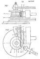
- the extruded profile 1 is shown in the figures. This extruded profile has the finished profile of the rim.
- the core stretching device has a core shape 2, this core shape 2 is also moved by the clamping jaw 5 in the direction of the arrow 18 by drivers 19, which are located on the turntable 20 of this core stretching device. This arrangement is important because the jaws must be moved in the direction of arrow 19 and then in the direction of arrow 21 when loosening, and by this entrainment the profile is protected, it is not exposed to great frictional forces, since it is only stressed at the clamping point by the power transmission. is deformed.
- the clamping jaw 5 and the core shape 2 have the finished profile.
- the straight extruded profile 1 is guided into the device in the direction of arrow 23, there being guide profiles 3 and counter profiles 4 which, pressed against one another, prevent the finished profile of the extruded profile 1 from being deformed when it is deformed in the core stretching device.
- the profile pieces for the guide profile, counter profile and the clamping jaws are made of an elastic material in order to reduce all deformations to a minimum.
- guide and counter profiles 3 and 4 are moved towards or away from one another in order to initiate or end the bending process.
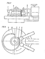
- the bending piece 6.1 which was subsequently present on the clamping piece 6, is now also removed; since it again had to take up the additional deformation work than after bending up to 360 degrees was rounded and now there is too large a diameter.
- This core roll bending device is then rounded by means of the forming rolls 8 and the core bending roll 9 until the finished diameter is reached.
- the end piece 6.1 can then be cut to length, which in turn had to take up substantial deformation work, as shown in FIG. 8, because this piece, as it were, acting as a lever, allows the rounding process.
- the turntable 11 also has guide disks 12 which are arranged above and below the extruded profile 1 in order to avoid springing open. These plates are not shown in detail in FIGS. 7 and 8.
- FIGS. 9 and 10 show the core roll bending process at a different point in time, namely, as shown in FIG. 10, when the weld joint has already formed because the finished dimension has been reached.
- two form rollers 8 are present; by moving in the direction of arrow 27 in one direction or the other, the contact pressure can be increased or decreased in accordance with the desired diameter.
- FIGS. 2 and 3 it is pointed out that a one-sided pre-bending is also sufficient, so that a two-sided pre-bending does not have to be carried out — as described above in FIGS. 2 and 3.
Landscapes
- Engineering & Computer Science (AREA)
- Mechanical Engineering (AREA)
- Bending Of Plates, Rods, And Pipes (AREA)
Applications Claiming Priority (2)
| Application Number | Priority Date | Filing Date | Title |
|---|---|---|---|
| DE3028956 | 1980-07-30 | ||
| DE19803028956 DE3028956A1 (de) | 1980-07-30 | 1980-07-30 | Verfahren zur herstellung von rundkoerpern |
Publications (1)
| Publication Number | Publication Date |
|---|---|
| EP0075599A1 true EP0075599A1 (fr) | 1983-04-06 |
Family
ID=6108510
Family Applications (2)
| Application Number | Title | Priority Date | Filing Date |
|---|---|---|---|
| EP81201085A Pending EP0045119A1 (fr) | 1980-07-30 | 1981-07-30 | Procédé pour la fabrication d'objets ronds |
| EP81902307A Ceased EP0075599A1 (fr) | 1980-07-30 | 1981-07-30 | Procede de preparation d'objets ronds |
Family Applications Before (1)
| Application Number | Title | Priority Date | Filing Date |
|---|---|---|---|
| EP81201085A Pending EP0045119A1 (fr) | 1980-07-30 | 1981-07-30 | Procédé pour la fabrication d'objets ronds |
Country Status (2)
| Country | Link |
|---|---|
| EP (2) | EP0045119A1 (fr) |
| DE (1) | DE3028956A1 (fr) |
Cited By (2)
| Publication number | Priority date | Publication date | Assignee | Title |
|---|---|---|---|---|
| DE4211065A1 (de) * | 1991-06-10 | 1992-12-17 | Banning Gmbh J | Verfahren und vorrichtung zur herstellung rotationssymetrischer teile aus metall |
| DE19949363C2 (de) * | 1999-10-13 | 2001-04-19 | Leico Werkzeugmaschb Gmbh & Co | Verfahren und Vorrichtung zur Herstellung eines Fahrzeugrades |
Families Citing this family (1)
| Publication number | Priority date | Publication date | Assignee | Title |
|---|---|---|---|---|
| US4674165A (en) * | 1983-06-09 | 1987-06-23 | Spaeth Walter | Method for manufacturing rounded parts, such as motor vehicle consisting of wheel rims |
Citations (4)
| Publication number | Priority date | Publication date | Assignee | Title |
|---|---|---|---|---|
| FR2042610A1 (fr) * | 1969-05-13 | 1971-02-12 | Grotnes Machine Works Inc | |
| DE2243293A1 (de) * | 1972-09-02 | 1974-03-07 | Lang Ludwig | Biegevorrichtung |
| DE2434108A1 (de) * | 1973-11-12 | 1975-05-15 | Grotnes Machine Works Inc | Verfahren zum bearbeiten einer schweissnaht von huelsen und einrichtung zum vorbereiten einer offenen huelse zum verschweissen der querkanten |
| DE2624872A1 (de) * | 1976-06-03 | 1977-12-08 | Bohner & Koehle | Verfahren zum herstellen von ungeteilten felgen |
-
1980
- 1980-07-30 DE DE19803028956 patent/DE3028956A1/de not_active Ceased
-
1981
- 1981-07-30 EP EP81201085A patent/EP0045119A1/fr active Pending
- 1981-07-30 EP EP81902307A patent/EP0075599A1/fr not_active Ceased
Patent Citations (4)
| Publication number | Priority date | Publication date | Assignee | Title |
|---|---|---|---|---|
| FR2042610A1 (fr) * | 1969-05-13 | 1971-02-12 | Grotnes Machine Works Inc | |
| DE2243293A1 (de) * | 1972-09-02 | 1974-03-07 | Lang Ludwig | Biegevorrichtung |
| DE2434108A1 (de) * | 1973-11-12 | 1975-05-15 | Grotnes Machine Works Inc | Verfahren zum bearbeiten einer schweissnaht von huelsen und einrichtung zum vorbereiten einer offenen huelse zum verschweissen der querkanten |
| DE2624872A1 (de) * | 1976-06-03 | 1977-12-08 | Bohner & Koehle | Verfahren zum herstellen von ungeteilten felgen |
Cited By (2)
| Publication number | Priority date | Publication date | Assignee | Title |
|---|---|---|---|---|
| DE4211065A1 (de) * | 1991-06-10 | 1992-12-17 | Banning Gmbh J | Verfahren und vorrichtung zur herstellung rotationssymetrischer teile aus metall |
| DE19949363C2 (de) * | 1999-10-13 | 2001-04-19 | Leico Werkzeugmaschb Gmbh & Co | Verfahren und Vorrichtung zur Herstellung eines Fahrzeugrades |
Also Published As
| Publication number | Publication date |
|---|---|
| EP0045119A1 (fr) | 1982-02-03 |
| DE3028956A1 (de) | 1982-03-04 |
Similar Documents
| Publication | Publication Date | Title |
|---|---|---|
| DE10050919B4 (de) | Verfahren zum Biegen von Metallrohren mit geringem Durchmesser und Vorrichtung hierfür | |
| DE2948115A1 (de) | Verfahren und vorrichtung zum formen von eine naht aufweisenden rohren von bogenfoermigem querschnitt aus flaechigem material, insbesondere blech | |
| DE102004060766A1 (de) | Biegevorrichtung für Rohre | |
| DE69011727T2 (de) | Verfahren zur Herstellung von Metallzylinderbauelementen für Entladungsröhren und Herstellungsverfahren für Magnetronanoden. | |
| DE2053005B2 (de) | Verfahren und vorrichtung zur herstellung von schraegschulterfelgen fuer lkw | |
| CH617876A5 (fr) | ||
| DE102018211311A1 (de) | Erweiterte Regelung JCO-Formpresse | |
| DE2624872C3 (de) | Verfahren zum Herstellen von ungeteilten Felgen | |
| DE4210227C2 (fr) | ||
| EP0045119A1 (fr) | Procédé pour la fabrication d'objets ronds | |
| DE2022424A1 (de) | Verfahren und Einrichtung zum Bilden von zylindrischen Rohlingen | |
| DE451529C (de) | Verfahren zur Herstellung von Rohren mit schraubenfoermig aufgewundenen Rippen | |
| DE2716940A1 (de) | Verfahren zur herstellung von laengsnahtrohren und walzwerk zur durchfuehrung dieses verfahrens | |
| DE2721269A1 (de) | Verfahren zum herstellen von ringfoermigen oder von bogenfoermig gekruemmten gegenstaenden | |
| DE2655639A1 (de) | Verfahren zur herstellung eines ringes | |
| DE3523044A1 (de) | Verfahren und vorrichtung zum herstellen von giessformen | |
| DE416539C (de) | Verfahren und Vorrichtung zur Herstellung von Metallrahmen | |
| EP0128570A2 (fr) | Procédé et dispositif pour la fabrication de corps ronds consistant en profilés métalliques spécialement de jantes de roues de véhicules automobiles | |
| DE102004015073B3 (de) | Vorrichtung und Verfahren zum Biegen eines Werkstücks | |
| DE2307134A1 (de) | Vorrichtung zum anbiegen der enden von blechen | |
| DE8020489U1 (de) | Vorrichtung zur herstellung von radfelgen fuer kraftfahrzeuge | |
| DE3008738A1 (de) | Verfahren und vorrichtung zum herstellen von aus blech, insbesondere leichtmetallblech gefertigten scheibenraedern | |
| DE710902C (de) | Verfahren zur Herstellung von Rohren und Profilen aller Art | |
| DE2208392C3 (de) | Verfahren und Vorrichtung zum Herstellen von Längsnahtrohren | |
| AT243599B (de) | Vorrichtung zum Zusammenschweißen von aus Stahlblech bestehenden Gliederhälften zu Radiatorgliedern |
Legal Events
| Date | Code | Title | Description |
|---|---|---|---|
| PUAI | Public reference made under article 153(3) epc to a published international application that has entered the european phase |
Free format text: ORIGINAL CODE: 0009012 |
|
| 17P | Request for examination filed |
Effective date: 19820324 |
|
| AK | Designated contracting states |
Designated state(s): AT CH FR GB LI NL |
|
| RBV | Designated contracting states (corrected) |
Designated state(s): AT BE CH FR GB IT LI NL |
|
| XX | Miscellaneous (additional remarks) |
Free format text: VERBUNDEN MIT 81201085.8/0045119 /EUROPAEISCHE ANMELDENUMMER/VEROEFFENTLICHUNGSNUMMER) DURCH ENTSCHEIDUNG VOM 25.09.84. |
|
| RBV | Designated contracting states (corrected) |
Designated state(s): VE BU DE |
|
| RBV | Designated contracting states (corrected) |
Designated state(s): VE BU DE |
|
| STAA | Information on the status of an ep patent application or granted ep patent |
Free format text: STATUS: THE APPLICATION HAS BEEN REFUSED |
|
| 18R | Application refused |
Effective date: 19851019 |
|
| RIN1 | Information on inventor provided before grant (corrected) |
Inventor name: SPAETH, WALTER |