EP0075689A1 - Instruments optiques pour observer la surface d'un échantillon - Google Patents
Instruments optiques pour observer la surface d'un échantillon Download PDFInfo
- Publication number
- EP0075689A1 EP0075689A1 EP82107229A EP82107229A EP0075689A1 EP 0075689 A1 EP0075689 A1 EP 0075689A1 EP 82107229 A EP82107229 A EP 82107229A EP 82107229 A EP82107229 A EP 82107229A EP 0075689 A1 EP0075689 A1 EP 0075689A1
- Authority
- EP
- European Patent Office
- Prior art keywords
- sample
- light beam
- beam splitter
- detectors
- sample position
- Prior art date
- Legal status (The legal status is an assumption and is not a legal conclusion. Google has not performed a legal analysis and makes no representation as to the accuracy of the status listed.)
- Ceased
Links
- 230000003287 optical effect Effects 0.000 title claims abstract description 12
- 230000010287 polarization Effects 0.000 abstract description 12
- 238000010586 diagram Methods 0.000 abstract description 2
- 230000003068 static effect Effects 0.000 abstract description 2
- 239000000523 sample Substances 0.000 description 23
- 238000005259 measurement Methods 0.000 description 6
- 230000008033 biological extinction Effects 0.000 description 2
- 230000001419 dependent effect Effects 0.000 description 2
- 239000000463 material Substances 0.000 description 2
- 238000000034 method Methods 0.000 description 2
- 230000010363 phase shift Effects 0.000 description 2
- RTAQQCXQSZGOHL-UHFFFAOYSA-N Titanium Chemical compound [Ti] RTAQQCXQSZGOHL-UHFFFAOYSA-N 0.000 description 1
- 238000010521 absorption reaction Methods 0.000 description 1
- 238000006243 chemical reaction Methods 0.000 description 1
- 239000004020 conductor Substances 0.000 description 1
- 238000013461 design Methods 0.000 description 1
- 239000003989 dielectric material Substances 0.000 description 1
- 230000000694 effects Effects 0.000 description 1
- 238000000572 ellipsometry Methods 0.000 description 1
- 238000002474 experimental method Methods 0.000 description 1
- 239000011521 glass Substances 0.000 description 1
- PCHJSUWPFVWCPO-UHFFFAOYSA-N gold Chemical compound [Au] PCHJSUWPFVWCPO-UHFFFAOYSA-N 0.000 description 1
- 239000010931 gold Substances 0.000 description 1
- 229910052737 gold Inorganic materials 0.000 description 1
- 238000005286 illumination Methods 0.000 description 1
- 238000011065 in-situ storage Methods 0.000 description 1
- 238000012544 monitoring process Methods 0.000 description 1
- 238000009304 pastoral farming Methods 0.000 description 1
- 238000000711 polarimetry Methods 0.000 description 1
- 238000012545 processing Methods 0.000 description 1
- 230000009467 reduction Effects 0.000 description 1
- 239000013074 reference sample Substances 0.000 description 1
- 239000004065 semiconductor Substances 0.000 description 1
- 229910052710 silicon Inorganic materials 0.000 description 1
- 239000010703 silicon Substances 0.000 description 1
- 239000007787 solid Substances 0.000 description 1
- 239000000126 substance Substances 0.000 description 1
- 239000000758 substrate Substances 0.000 description 1
- 229910052719 titanium Inorganic materials 0.000 description 1
- 239000010936 titanium Substances 0.000 description 1
Images
Classifications
-
- G—PHYSICS
- G01—MEASURING; TESTING
- G01N—INVESTIGATING OR ANALYSING MATERIALS BY DETERMINING THEIR CHEMICAL OR PHYSICAL PROPERTIES
- G01N21/00—Investigating or analysing materials by the use of optical means, i.e. using sub-millimetre waves, infrared, visible or ultraviolet light
- G01N21/17—Systems in which incident light is modified in accordance with the properties of the material investigated
- G01N21/21—Polarisation-affecting properties
- G01N21/211—Ellipsometry
Definitions
- the invention relates to optical instruments for viewing a sample surface. Such instruments are used in polarimetry and ellipsometry.
- the sources of error in Smith overcome by the present arrangement are 1) alignment of the beam; 2) uniformity of the beam, and 3) uniformity of the sample.
- the present arrangement permits focussing upon sample object surface areas as small as 1 mil 2 whereas Smith cannot, since his error is on the order of a few mils 2 , Smith states that he requires uniform illumination (p. 219) and a large area (p. 213).
- the result is a more complex set of twice as many data outputs, and five detectors instead of three with the attendant disadvantages of more sources of error and cost of computation.
- the present system employs a novel technique, which permits use of only three detectors, whereas heretofore, it had been believed that four detectors would be required.
- an instrument comprising a source of a polarized light beam directed towards a sample position.
- Means is provided for supporting a sample in the sample position.
- a polarizing beam splitter is supported for reception of the reflection of the beam from the surface of a sample in the sample position and a pair of detectors for p and s beams is positioned to receive the p and s portions of said light beam from the polarizing beam splitter.
- the source includes means for polarization of the light beam, which preferably polarizes the light beam at 45°, or provides circular polarization of the light beam.
- a beam splitter splits the light beam and directs a portion thereof to a third detector and directs the remainder of the light beam to the sample.
- the invention therefore provides an optical instrument comprising a source of polarised light beam directed towards a sample position, means for supporting a sample in the sample position, and analysising means for reception of the beam reflected from the sample characterised in that the analysing means comprise a polarising beam splitter and a pair of detectors positioned respectively to receive the perpendicularly polarised portions of the light beam emerging from the beam splitter.
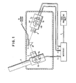
- FIG. 1 shows a chamber containing sample S held in place on fixture F by means of pressure induced by vacuum line V.
- a laser L (in this paricular case shown as about eleven inches long) is directed towards beam splitter BS which passes a portion of the beam to photodiode D and reflects the remainder of the beam towards the sample S.
- the beam reflected from beam splitter BS passes through polarizer P.
- polarizer P can be omitted since the laser beam is polarized.
- Polarizer P enhances the polarization.
- the beam is directed at the sample at an angle 0 of 70° with respect to a line normal to the surface of the sample S . Angles which are preferred range from a few degrees to close to 90°.
- a measurement of a single interface cannot be done but a multiple layer structure can be measured.
- the beam reflected from the surface of the sample is passed through aperture A (which eliminates spurious light) to a polarizing beam splitter PBS (comprising preferably a Wollaston prism) which produces a first beam directed to the photodiode D p and a second beam directed to a second photodiode D s with the two beams separated in the plane defined by the beams by an angle of 20°. Any angle can be used, but larger angles are preferred in a practical application.
- the outputs of sensor D , sensor D and sensor D pass s through lines G, H and I respectively to the interface which is connected by cable J to the data processing unit.
- the polarizing beam splitter produces two different polarizations of the beam for the two photodiodes D p and D .
- the polarimeter of the instant invention is an instrument of the static photometric type and its resolving time is limited only by the rise times of its photodetectors.
- beam splitter BS and sensor D o can be omitted if a standard reference sample is available to calibrate measurements.
- the purpose of beam splitter BS and sensor D o is to eliminate the effects of variation of the intensity of the laser beam from laser L.
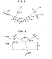
- the polarimeter shown in FIG. 2, utilizes a single polarized beam (polarized, say, at 45° to the plane of incidence) from a small HeNe laser L (or any other collimated beam in combination with a polarizer).
- a beam splitter BS directs a fraction of the incident beam to normalizing detector D o .
- a polarizing beam splitter PBS (such as a Wollaston prism) splits the reflected beam from sample S into its "p" (parallel) and "s" (perpendicular) polarization components which are then monitored by detectors D and D .
- p s such as a Wollaston prism
- the "p" and "s” intensity reflection coefficients R and R can p s be derived. For example, for light polarized at 45° and an incident beam splitting ratio of 1:2 (i.e., I o equals one-third of the source beam intensity), the intensity reflection coefficients are given by
- a circularly polarized beam can be used instead of a plane polarized incident beam.
- a 1/4 wavelength plate suitably oriented will convert any plane polarized light to circular polarization. This will not affect the operation of the ellipsometer because the only difference is 90° of phase delay between the "p" and "s" polarized components which does not affect the photodetectors. The results are identical to those obtained using a 45° polarized incident beam.
- samples were measured with reasonable accuracy at an incident angle of 70°. These included dielectrics (glasses), semiconductors (silicon) and conductors (gold and titanium).
- the source was a 5 mw HeNe laser and the detectors were (photodiode/Op-amp combinations) with a rise time of about 100 nanoseconds.
- the intensity reflection coefficients R p and R could be observed directly through the use of two digital ratiometers. Practical applications of this invention include measurements of values as follows:
- this invention provides a fast response, general purpose polarimeter (simple design, no moving parts).
- r s and rp are the amplitude reflection coefficients
- N 1 and N 2 are the indices of refraction of the media (light is incident from medium 1 onto medium 2) and is the angle of incidence as shown in FIG. 3.
- FIG. 3 shows reflection and refraction at an interface with p polarization.
- N N 2 /N 1 is the relative index of refraction.
- equation 4 yields r - r s 2 and equation 5 cannot be used to determine the "s"-polarization phase shift
Landscapes
- Physics & Mathematics (AREA)
- Health & Medical Sciences (AREA)
- Life Sciences & Earth Sciences (AREA)
- Chemical & Material Sciences (AREA)
- Analytical Chemistry (AREA)
- Biochemistry (AREA)
- General Health & Medical Sciences (AREA)
- General Physics & Mathematics (AREA)
- Immunology (AREA)
- Pathology (AREA)
- Investigating Or Analysing Materials By Optical Means (AREA)
Applications Claiming Priority (2)
| Application Number | Priority Date | Filing Date | Title |
|---|---|---|---|
| US30655981A | 1981-09-28 | 1981-09-28 | |
| US306559 | 1981-09-28 |
Publications (1)
| Publication Number | Publication Date |
|---|---|
| EP0075689A1 true EP0075689A1 (fr) | 1983-04-06 |
Family
ID=23185843
Family Applications (1)
| Application Number | Title | Priority Date | Filing Date |
|---|---|---|---|
| EP82107229A Ceased EP0075689A1 (fr) | 1981-09-28 | 1982-08-10 | Instruments optiques pour observer la surface d'un échantillon |
Country Status (2)
| Country | Link |
|---|---|
| EP (1) | EP0075689A1 (fr) |
| JP (1) | JPS5863836A (fr) |
Cited By (10)
| Publication number | Priority date | Publication date | Assignee | Title |
|---|---|---|---|---|
| EP0150945A3 (fr) * | 1984-02-02 | 1986-05-28 | Lawrence S. Canino | Procédé et appareil pour la mesure des propriétés de matériaux de faible épaisseur |
| EP0200978A1 (fr) * | 1985-04-23 | 1986-11-12 | CSELT Centro Studi e Laboratori Telecomunicazioni S.p.A. | Ellipsomètre interférométrique statique |
| FR2629590A1 (fr) * | 1988-03-30 | 1989-10-06 | Schlumberger Ind Sa | Dispositif et procede polarimetriques a resolution amelioree |
| EP0371550A1 (fr) * | 1988-11-28 | 1990-06-06 | Hoogovens Groep B.V. | Méthode de mesure de l'épaisseur de couches minces |
| DE4105192A1 (de) * | 1990-02-26 | 1991-08-29 | Stefan Oelckers | Polarimetrisches verfahren und vorrichtung zur bestimmung von eigenschaften von materialoberflaechen und transparenten materialien sowie zur winkelmessung |
| EP0493815A3 (en) * | 1990-12-27 | 1992-10-14 | Hitachi Electronics Engineering Co., Ltd. | Apparatus for detecting extraneous substance on glass plate |
| US5557399A (en) * | 1995-03-22 | 1996-09-17 | Zygo Corporation | Optical gap measuring apparatus and method |
| US5751427A (en) * | 1995-03-22 | 1998-05-12 | Zygo Corporation | Optical gap measuring apparatus and method |
| US5953125A (en) * | 1995-09-01 | 1999-09-14 | Zygo Corporation | Optical gap measuring apparatus and method |
| EP1619465A1 (fr) * | 2004-07-19 | 2006-01-25 | Nederlandse Organisatie Voor Toegepast-Natuurwetenschappelijk Onderzoek Tno | Dispositif et procédé de surveillance optique de couches |
Families Citing this family (3)
| Publication number | Priority date | Publication date | Assignee | Title |
|---|---|---|---|---|
| JPH10281991A (ja) * | 1997-04-11 | 1998-10-23 | Stanley Electric Co Ltd | 光沢センサ |
| JP3707241B2 (ja) * | 1998-05-12 | 2005-10-19 | 富士電機システムズ株式会社 | 油膜検知装置 |
| JP6195777B2 (ja) * | 2013-10-22 | 2017-09-13 | Hoya株式会社 | 複屈折の測定方法、マスクブランク用基板の製造方法、マスクブランクの製造方法、転写用マスクの製造方法および半導体デバイスの製造方法 |
Citations (3)
| Publication number | Priority date | Publication date | Assignee | Title |
|---|---|---|---|---|
| US3653767A (en) * | 1967-04-10 | 1972-04-04 | American Standard Inc | Particle size distribution measurement using polarized light of a plurality of wavelengths |
| US3904293A (en) * | 1973-12-06 | 1975-09-09 | Sherman Gee | Optical method for surface texture measurement |
| US3995957A (en) * | 1975-10-16 | 1976-12-07 | The United States Of America As Represented By The Secretary Of The Navy | Internally referenced, laser intracavity technique for measuring small gains or losses |
Family Cites Families (1)
| Publication number | Priority date | Publication date | Assignee | Title |
|---|---|---|---|---|
| JPS5314943B2 (fr) * | 1973-12-31 | 1978-05-20 |
-
1982
- 1982-08-10 EP EP82107229A patent/EP0075689A1/fr not_active Ceased
- 1982-09-16 JP JP15972982A patent/JPS5863836A/ja active Pending
Patent Citations (3)
| Publication number | Priority date | Publication date | Assignee | Title |
|---|---|---|---|---|
| US3653767A (en) * | 1967-04-10 | 1972-04-04 | American Standard Inc | Particle size distribution measurement using polarized light of a plurality of wavelengths |
| US3904293A (en) * | 1973-12-06 | 1975-09-09 | Sherman Gee | Optical method for surface texture measurement |
| US3995957A (en) * | 1975-10-16 | 1976-12-07 | The United States Of America As Represented By The Secretary Of The Navy | Internally referenced, laser intracavity technique for measuring small gains or losses |
Non-Patent Citations (1)
| Title |
|---|
| SURFACE SCIENCE, vol. 56, no. 1, June 1976, Amsterdam. T. SMITH: "An automated scanning ellipsometer" pages 212 to 220 * |
Cited By (15)
| Publication number | Priority date | Publication date | Assignee | Title |
|---|---|---|---|---|
| EP0150945A3 (fr) * | 1984-02-02 | 1986-05-28 | Lawrence S. Canino | Procédé et appareil pour la mesure des propriétés de matériaux de faible épaisseur |
| EP0200978A1 (fr) * | 1985-04-23 | 1986-11-12 | CSELT Centro Studi e Laboratori Telecomunicazioni S.p.A. | Ellipsomètre interférométrique statique |
| US4762414A (en) * | 1985-04-23 | 1988-08-09 | Cselt-Centro Studi E Laboratori Telecomunicazioni S.P.A. | Static interferometric ellipsometer |
| FR2629590A1 (fr) * | 1988-03-30 | 1989-10-06 | Schlumberger Ind Sa | Dispositif et procede polarimetriques a resolution amelioree |
| EP0337829A1 (fr) * | 1988-03-30 | 1989-10-18 | Schlumberger Industries | Dispositif et procédé polarimetriques à resolution ameliorée |
| US5170049A (en) * | 1988-11-28 | 1992-12-08 | Hoogovens Groep B.V. | Coating thickness gauge using linearly polarized light |
| EP0371550A1 (fr) * | 1988-11-28 | 1990-06-06 | Hoogovens Groep B.V. | Méthode de mesure de l'épaisseur de couches minces |
| DE4105192A1 (de) * | 1990-02-26 | 1991-08-29 | Stefan Oelckers | Polarimetrisches verfahren und vorrichtung zur bestimmung von eigenschaften von materialoberflaechen und transparenten materialien sowie zur winkelmessung |
| EP0493815A3 (en) * | 1990-12-27 | 1992-10-14 | Hitachi Electronics Engineering Co., Ltd. | Apparatus for detecting extraneous substance on glass plate |
| US5245403A (en) * | 1990-12-27 | 1993-09-14 | Hitachi Electronics Engineering Co., Ltd. | Apparatus for detecting extraneous substances on a glass plate |
| US5557399A (en) * | 1995-03-22 | 1996-09-17 | Zygo Corporation | Optical gap measuring apparatus and method |
| US5751427A (en) * | 1995-03-22 | 1998-05-12 | Zygo Corporation | Optical gap measuring apparatus and method |
| US5953125A (en) * | 1995-09-01 | 1999-09-14 | Zygo Corporation | Optical gap measuring apparatus and method |
| EP1619465A1 (fr) * | 2004-07-19 | 2006-01-25 | Nederlandse Organisatie Voor Toegepast-Natuurwetenschappelijk Onderzoek Tno | Dispositif et procédé de surveillance optique de couches |
| WO2006009440A1 (fr) * | 2004-07-19 | 2006-01-26 | Nederlandse Organisatie Voor Toegepast-Natuurwetenschappelijk Onderzoek Tno | Appareil et procede d'examen de revetements optiques |
Also Published As
| Publication number | Publication date |
|---|---|
| JPS5863836A (ja) | 1983-04-15 |
Similar Documents
| Publication | Publication Date | Title |
|---|---|---|
| US4585348A (en) | Ultra-fast photometric instrument | |
| US5877859A (en) | Broadband spectroscopic rotating compensator ellipsometer | |
| Hauge et al. | A rotating-compensator Fourier ellipsometer | |
| US4647207A (en) | Ellipsometric method and apparatus | |
| US5042951A (en) | High resolution ellipsometric apparatus | |
| CA2003983C (fr) | Calibre d'epaisseur pour revetement | |
| EP0397388A2 (fr) | Procédé et appareil de mesure de l'épaisseur de films minces | |
| IL107549A (en) | Device for measuring the thickness of thin films | |
| EP0075689A1 (fr) | Instruments optiques pour observer la surface d'un échantillon | |
| EP0396409B1 (fr) | Dispositif d'ellipsométrie à grand pouvoir de résolution | |
| EP0200978B1 (fr) | Ellipsomètre interférométrique statique | |
| US3449051A (en) | Differential optical system and optical elements therefor | |
| Azzam et al. | Conventional and generalized Mueller-matrix ellipsometry using the four-detector photopolarimeter | |
| Azzam | Multichannel polarization state detectors for time-resolved ellipsometry | |
| Azzam | NIRSE: Normal-incidence rotating-sample ellipsometer | |
| US3481671A (en) | Apparatus and method for obtaining optical rotatory dispersion measurements | |
| JPH0571923A (ja) | 偏光解析方法および薄膜測定装置 | |
| EP0102470B1 (fr) | Ellipsomètres | |
| WO1994016310A1 (fr) | Ellipsometre de zeeman | |
| Zaghloul et al. | Single-element rotating-polarizer ellipsometer: psi meter | |
| JPH11101739A (ja) | エリプソメトリ装置 | |
| Azzam | Ellipsometric Methods of Characterization of Optical Thin Films | |
| RU2749149C1 (ru) | Двухсторонний скоростной эллипсометр | |
| JPH07111327B2 (ja) | 偏光解析装置 | |
| Mansuripur | Ellipsometry |
Legal Events
| Date | Code | Title | Description |
|---|---|---|---|
| PUAI | Public reference made under article 153(3) epc to a published international application that has entered the european phase |
Free format text: ORIGINAL CODE: 0009012 |
|
| AK | Designated contracting states |
Designated state(s): DE FR GB |
|
| 17P | Request for examination filed |
Effective date: 19830722 |
|
| STAA | Information on the status of an ep patent application or granted ep patent |
Free format text: STATUS: THE APPLICATION HAS BEEN REFUSED |
|
| 18R | Application refused |
Effective date: 19860501 |
|
| RIN1 | Information on inventor provided before grant (corrected) |
Inventor name: HILDENBRAND, WALTER WILLIAM Inventor name: LEVANONI, MENACHEM Inventor name: CHASTANG, JEAN-CLAUDE ANDRE |