EP0075724A2 - Mécanisme à mise de feu électrique pour armes à feu - Google Patents
Mécanisme à mise de feu électrique pour armes à feu Download PDFInfo
- Publication number
- EP0075724A2 EP0075724A2 EP82107674A EP82107674A EP0075724A2 EP 0075724 A2 EP0075724 A2 EP 0075724A2 EP 82107674 A EP82107674 A EP 82107674A EP 82107674 A EP82107674 A EP 82107674A EP 0075724 A2 EP0075724 A2 EP 0075724A2
- Authority
- EP
- European Patent Office
- Prior art keywords
- trigger
- fire
- shot
- firing device
- switch
- Prior art date
- Legal status (The legal status is an assumption and is not a legal conclusion. Google has not performed a legal analysis and makes no representation as to the accuracy of the status listed.)
- Granted
Links
Images

Classifications
-
- F—MECHANICAL ENGINEERING; LIGHTING; HEATING; WEAPONS; BLASTING
- F41—WEAPONS
- F41A—FUNCTIONAL FEATURES OR DETAILS COMMON TO BOTH SMALLARMS AND ORDNANCE, e.g. CANNONS; MOUNTINGS FOR SMALLARMS OR ORDNANCE
- F41A19/00—Firing or trigger mechanisms; Cocking mechanisms
- F41A19/58—Electric firing mechanisms
- F41A19/60—Electric firing mechanisms characterised by the means for generating electric energy
- F41A19/62—Piezoelectric generators
Definitions
- the invention relates to a firing device on weapons, in particular on handguns and small-caliber machine guns, with a mechanical trigger that excites a force storage device and a piezoelectric force that acts as a current source when a shot is triggered by the trigger from the tensioned energy storage device.
- a mechanical trigger that excites a force storage device and a piezoelectric force that acts as a current source when a shot is triggered by the trigger from the tensioned energy storage device.
- s p annungserzeuger whose output is connected to an electrical detonator for a projectile driving propellant charge, with a selector switch for switching at least one fuse for locking the trigger and / or for interrupting the power flow from the power storage to the piezo-voltage generator and / or the current flow from the Piezo voltage generator to the igniter.
- Such firing devices are known. They generally comprise a piezo voltage generator, the output of which is connected to an electrical igniter. To generate the ignition current surge, a spring is generally tensioned by the trigger (tension trigger) and triggered towards the end of the trigger path, the spring accelerating a mass that generates the desired current surge upon impact with the piezoelectric element of the piezo voltage generator, which directly or via a charging capacitor Detonator is fed. If the safety that a clamping trigger offers is dispensed with, the energy accumulator can also be cocked independently of the trigger and the trigger can only be used to trigger the cocked energy accumulator. (DE-OS 20 48 743)
- Such firing devices are indeed suitable for individual shots, but not readily for bursts of fire, that is to say the firing of a predetermined number of shots and for continuous fire, the weapon firing as long as the trigger is pulled.
- the electric ignition has the advantage that it can be encapsulated in a relatively simple manner in a dustproof and waterproof manner, which is of considerable importance for military weapons. It is also important that electrical ignition is significantly less dependent on temperature influences, has a lower weight and takes up less space. After all, almost any security requirements and combinations can be easily implemented in the case of electrically fired weapons.
- a firing device of the type mentioned in the present invention in that a further, preferably electrochemical, power source is provided for firing the second and each additional shot in the "burst of fire” and “continuous fire” operating modes, and that this power source can be connected to the igniter by the trigger.
- the trigger system can be designed as a trigger trigger, which offers a high level of security against false triggering even when no further protection is provided.
- a second, electrochemical power source i.e. a battery
- the firing of the further shots is independent of the generation of an impact energy, because this is supplied by the power source (battery).
- the safety selector switch for use as a fire selector switch has the "permanent" and “burst” positions in addition to the "safe" and “single fire” positions.
- the combination of the safety selector switch with the fire selector switch simplifies the construction and increases the operational reliability as well as the handling safety, which is greater the fewer operating elements that the shooter has to actuate.
- a mechanical shot counter can be used, which in the Position "burst of fire” ends the firing process after firing a predetermined number of shots.
- shot counters are known for firearms.
- the firing cadence can be determined in a known manner by the forces and existing masses in the previously explained embodiments.
- an electrical circuit is fed from the current source in the "continuous fire” and “burst of fire” positions, which controls the ignition current as a function of a cadence sensor and / or counter.
- the electronic counter of this circuit serves as a shot counter that, after reaching a preset number, ends the burst of fire by generating a corresponding switching signal.
- a clock generator can be provided as a cadence generator in order to be able to adapt the weft cadence to any requirements (the maximum weft cadence being of course limited by the mechanical properties of the closure).
- the pulse generator which serves as a cadence generator, can be set to different frequencies with very little effort, so that starting from a maximum value, any shot cadence can be set downwards. Since then, this has not been possible with weapons with mechanical ignition or piezoelectric ignition operated by the breech.
- the electronic circuit comprises a voltage converter for increasing the voltage of the current source.
- the highly transformed voltage required for firing is only built up after the piezo-fired shot has been triggered or, in the case of a shotgun trigger, after the trigger has been actuated, which significantly increases the safety of the weapon.
- the same igniter can be ignited on the one hand with an inexpensive, commercially available low-voltage power source and on the other hand with the piezo voltage generator (high-voltage high-voltage generator).
- the current source can be connected to the electronic circuit and the igniter by a switch actuated by the trigger.
- this has the advantage that when the trigger is mechanically locked and the safety selector switch is in the "safe" position, an ignition cannot be triggered accidentally.
- the power source is always reliably separated from the electronic circuit and the detonator because the trigger always returns to its starting position when the weapon is not in use, in which the switches are open. This ensures that the power source is not loaded when the trigger is not actuated and therefore does not need to be replaced for the duration of its shelf life.
- the precaution to have to replace the power source under legal conditions can be omitted, i.e. it can be completely sealed and protected in the weapon in a structurally unproblematic manner.
- a transmitter is attached to the closure and connected to the electronic circuit for generating a control signal when the closure is closed. With its signaling, this transmitter ensures that a shot is only possible when the shot is completely closed
- the transmitter can be designed as a contactless transmitter (proximity switch) known per se or as a contact. In the latter case, it can also be placed directly in the feed line to the detonator and thus prevent a shot from being triggered even in the "single fire" position when the breech is not fully closed.
- the safety of the weapon that can be achieved by means of a trigger trigger should not be dispensed with and, on the other hand, it should nevertheless be possible to fire the first shot without great trigger resistance and thus with high accuracy.
- This can be achieved, for example, in that the energy store can also be tensioned by another tensioning element in addition to the trigger.
- this requires an additional mechanical effort.
- a further operating mode "shotgun" can be switched on, in which the ignition energy for the first shot can be supplied from the power source, in which operating mode the shot can be triggered with little or no tensioning of the energy store.
- the shotgun operating mode is switched on exclusively by actuating the electric fire selector switch.
- the trigger which triggers the shot in this type of fire and is actuated by the trigger is also actuated in the case of the other types of fire, for example continuous fire, but does not then cause a shot to be fired directly.
- the trigger can be moved in the usual operating modes and swiveled in the "shotgun" operating mode, and the switchover to the "shotgun” operating mode takes place by mechanically changing the trigger movement.
- This mechanical changeover of the trigger movement from pivotable to displaceable or vice versa is preferably carried out by means of the fire selector switch, which in any case comprises a mechanical actuating element, for example an adjusting knob or adjusting lever.
- the electronic circuit is designed so that in the "shotgun" operating mode, only one shot can be triggered each time the trigger is actuated. This can be achieved, for example, by setting the shot counter to IJ 1 "in this operating mode. Or a flip-flop is provided, which can be pulled into one and the ignition pulse or the signal from the sensor attached to the breech into the other position is tiltable.
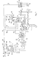
- a trigger 1 of a weapon can either be pivoted about a bolt 2 or moved in the longitudinal direction of an elongated hole 3, at the end of which the bolt 2 bears under the action of a compression spring 4 in the rest position of the trigger 1.
- the pressure spring 4 serving as an energy accumulator and designed as a helical compression spring is supported on the other hand against an impact piece 5, which is displaceably guided in the direction of force of the compression spring 4 and locked by an angle lever 6, which can be pivoted about an axis 7 and the end of which is provided with a locking hook 8 that engages behind the striking piece 5.
- the angle lever 6 can be pivoted out by a projection 9 integrally formed on the trigger 1, which comes to rest on an arm of the angle lever 6 after the trigger 1 has been displaced in the longitudinal direction of the elongated hole 3 by tensioning the compression spring 4.
- a piezo voltage generator 10 is arranged in the path of movement of the striking element 5, which is connected to ground on the one hand via a connection 11 and to which on the other hand a pulse line 12 is connected, which leads to a contact 13 of a switch 14.
- the switch 14 has a further contact 15, which is connected to ground, alternatively the contacts 13 or 15 can be connected via a movable contact spring 16 to a connection 17, from which an ignition line 18 leads to a pole of an electrical igniter 19, which is part of a Cartridge 20 is located in the barrel of the weapon, not shown.
- the other pole of the electrical detonator 19 is connected to ground via the cartridge case or, in the case of caseless cartridges, a further connection 21.
- the connection of the ignition line 18 with the electrical igniter 19 is produced via a closure piece 22, for example by a contact pin, not shown, which is used in an electrically insulated manner instead of a firing pin.
- the breech 22 is known to be movable in the direction of a double arrow 23 in such weapons.
- a transmitter designed as a normally closed contact 59 is provided, which is closed when the closure piece 22 is in the closed position and is opened when the closure piece 22 is not or not completely in the closed position.
- a current source in the form of a battery 24 is connected to ground on the one hand via a connection 25 and, on the other hand, is connected via a line 26 to a pole 27 of a switch 28, the contact piece of which rests on a normally open contact 29 when the switch is closed.
- a further switch 30 is provided, one pole 31 of which is connected to the pole 27 and whose contact spring is connected to a normally open contact 32 when the switch 30 is closed.
- the switches 14, 28 and 30 can all be switched mechanically from the trigger 1.
- the arrangement is such that the switches 14 and 28 can be actuated when the trigger is moved in the longitudinal direction of the elongated hole 3 or in the direction of the force of the compression spring 4, but not when the trigger 1 is pivoted about the bolt 2 can be actuated when the trigger 1 is pivoted about the bolt 2, but not when the trigger 1 is pushed in the direction of the elongated hole 3.
- a fire selector switch 33 is used to set the various types of use or operating modes five different positions can be switched: “shotgun”, “safe”, “single shot”, “burst of fire” and “continuous fire”.
- trigger 1 can be actuated very easily, as can be achieved mechanically in rifles with an engraver. This allows a shot to be fired very precisely because the trigger weight is very low.
- no shot can be triggered.
- a single shot is fired when trigger 1 is actuated.
- To fire another shot let go and pull the trigger 1 again.
- the "burst of fire” position a series of shots of usually three shots is triggered by actuating trigger 1. The number of shots is limited by a shot counter. After releasing trigger 1 and pulling it again, another burst of fire can be fired.
- the weapon shoots continuously after trigger 1 is pulled until trigger 1 is released (or the magazine is empty).
- the fire selector switch 33 acts partly mechanically as a fuse and changeover switch and partly as an electrical switch.
- a radial hook lever 35 is fastened to the shaft (not shown) which can be pivoted about an axis 34 of the fire selector switch 33 and which engages behind an extension 36 of the trigger 1 in the "safe" and "shotgun” positions.
- the trigger 1 is mechanically locked against displacement in the longitudinal direction of the elongated hole 3.
- a nose 37 is provided, which comes into contact with the arm of an angle lever 38 when the fire selector switch 33 swivels into the "shotgun” position and pivots the latter about an axis 39.
- a guide surface 40 is pivoted out on the other arm of the angle lever 38 and the trigger 1 can be pivoted about the bolt 2 (but not shifted in the longitudinal direction because the end of the hook lever 35 still engages behind the shoulder 36).
- the hook lever 35 In the “safe” (S) and “shotgun” (Fl) positions, the hook lever 35 is engaged. In the remaining positions “single fire” (E), “burst of fire” (F) and “continuous fire” (D) the hook lever 35 has no effect.
- the shaft of the fire selector switch 33 also carries a contact bridge 41, which connects two opposing contacts to one another.
- a contact bridge 41 which connects two opposing contacts to one another.
- the contacts 44 and 46 are connected to one another and to ground.
- the contact 42 is connected via a line 52 to the normally open contact 32 of the switch 30, whereas the contacts 48 and 50 are connected to one another and via a line 53 to the normally open contact 29 of the switch 28.
- the contacts 45 and 47 are also connected to one another and to an electronic circuit 55 via a line 54.
- the contact 49 is connected to the electronic circuit 55 via a line 56, the contact 51 via a line 57 and the contact 43 via a line 58. Furthermore, the two connections of the normally closed contact 59 are connected to the electronic circuit 55 via lines 60 and 61. Finally, an ignition line 62 leads from the electronic circuit 55 to the ignition line 18 in lines 18 and 62 diodes 63 and 64 switched on for mutual decoupling of the electronic circuit 55 and the piezo voltage generator 10 from one another.
- the electronic circuit 55 essentially comprises a clock 65, which is connected as an astable multivibrator and the frequency of which can be adjusted by means of a variable resistor 66, and a monostable multivibrator 82 which brings the clock 65 and the voltage converter 70 into operation.
- An adjustable or fixed counter 67 serves as a shot counter.
- the logic operations are carried out by an AND gate 68 and an OR gate 69.
- a voltage converter 70 which converts the voltage of the battery 24 to the value required for the igniter 19, is used to generate the voltage required for the igniter 19.
- a switching element 71 for example a thyristor, is connected downstream of the voltage converter 70 via a line 72.
- the ignition line 62 is connected to the output of the switching element 71.
- the output of the clock generator 65 is connected on the one hand to an input of the AND gate 68 and on the other hand to an input of the counter 67 via a clock line 73.
- the output of the counter 67 is connected via a counting line 74 to an input of the OR gate 69, the output of which is connected to a further input of the AND gate 68.
- Line 57 is guided to a further input of OR gate 69, whereas the third input of OR gate 69 is connected to line 58.
- Two further inputs of the AND gate 68 are connected to the output of the voltage converter 70 and the line 61.
- the output of the AND gate 68 is connected to a control line 75 with a the control input of the switching element 71 connected.
- the power supply connections of the clock generator 65, the monostable multivibrator 82, the AND gate 68, the OR gate 69, the voltage converter 70 and the inverter 81 are connected to a feed line 76 to which the lines 60 and 54 are also connected.
- the lines 58, 56, and 57 are connected to the feed line 76 via the decoupling diodes 77, 78 and 79.
- switch 30 In position Fl, switch 30 is closed after actuating trigger 1 (pivoting about pin 2) after a short distance. As a result, feed current flows through line 58 to the individual switching groups of electronic circuit 55 with the exception of counter 67.
- the voltage on control line -58 tilts monostable multivibrator 82 and clock generator 65 is switched via control line 83, voltage converter 70 via Control line 84 brought into operation.
- a signal reaches the corresponding input of the AND gate 68 via the OR gate 69.
- a flip-flop 80 is provided, the power supply and control input of which is connected to line 58, whereas its reset input is connected to ignition line 62. Its output is connected to an inverter 81, the output of which is connected to a further input of the AND gate 68. No signal is present at the output of flip-flop 80 if it has been flipped from line 58; a signal is present when it has been tipped back from line 62.
- the inverter 81 reverses this signal, so that a signal is always present at the output of the inverter 81, except when a shot has been fired in the position F1 and the flip-flop 80 has been tilted by the ignition line 62.
- a signal at the output of flip-flop 80 can only be present if it is connected to the current source via line 58, which is only the case in position F1.
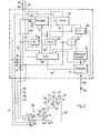
- FIG. 3 shows an embodiment of a firing device that differs from FIG. 1.
- the parts corresponding to Fig. 1 are largely no longer shown.
- the same reference number is used as in FIG. 1, provided that the parts shown are similar in function but differ in arrangement or design, a reference number 100 is higher than in FIG Fig. 1 used. Only the differences from the device shown in FIG. 1 will be discussed below.
- the fire selector switch 133 differs from the fire selector switch 33 according to FIG. 1 in that, starting from the "safe" position shown, it must be rotated counterclockwise to the position F1, the position F1 only after the positions E, F and D have been crossed is achieved.
- the switch contact connected to the switch contact 43 in the operating mode F1 bears the reference number 142, and this switch contact 142 is electrically connected to the switch contacts 48 and 50, that is to say also to the connection 29 of the switch 28.
- the switch 30 in FIG 3 arrangement not provided. Line 52 of FIG. 1 is also omitted.
- the trigger 101 is only displaceable in a linear manner, in the same direction as in FIG. 1, but not also pivotable. This is represented by two schematically indicated sliding guides 90 and 91.
- the switches 28 and 14 also provided in FIG. 1 are actuated in all operating modes in the same way as is the case with switches 14 and 28 in FIG. 1 in the operating modes E, F, D.
- the firing device according to FIG. 3 works exactly like that according to FIG. 1.
- the switches 14 and 28 are actuated, namely the switch 14 is switched so that the line 12 is now connected to the line 18, and also the switch 28 is closed so that the battery voltage is now supplied to the line 53 becomes.
- the arrangement is expediently such that the switch 14 switches first and the switch 29 closes shortly thereafter.
- the battery voltage supplied to the switch contact 142 via the line 53 reaches the contact 43 when the switch 29 is closed via the contact bridge 41 of the fire selector switch 133 and from there, as in the arrangement according to FIG. 1, via line 58 to the electronic circuit 55 then fires a single shot.
- FIGS. 1 and 3 if switch 14 has switched to the right by moving trigger 1 or 101 in the figures and switch 29 is closed, another trigger movement of trigger 1 or 101 in the same applies to FIGS Direction the switch position of switches 14 and 29 may no longer change.
- This act thing is not apparent from the very schematic representation in FIGS. 1 and 3.
- the arrangement will be made, for example, so that trigger cams 1 and 101, expediently at its extension 9 and 109, respectively, have switching cams - which exert a force on the movable part of the switches 14 and 29 when the trigger is moved .
- the switches 14 and 29 are arranged in the vicinity of the said switching cams so that the said force acts essentially at right angles to the direction of displacement of the trigger 1 or 101 on the switches 14 or 29.
- the cams have such a shape that after the triggering of the switching process, the switch position no longer changes after the trigger is pushed.
- the position F1 can also be set by a separate mechanical switching lever in the arrangement shown in FIG.
- the counter 67 can also be an arbitrarily adjustable counter in order to be able to change the number of shots of a burst of fire as desired.
Landscapes
- Engineering & Computer Science (AREA)
- General Engineering & Computer Science (AREA)
- Curing Cements, Concrete, And Artificial Stone (AREA)
- Polymerisation Methods In General (AREA)
- Respiratory Apparatuses And Protective Means (AREA)
- Automotive Seat Belt Assembly (AREA)
- Air Bags (AREA)
- Buildings Adapted To Withstand Abnormal External Influences (AREA)
- Incineration Of Waste (AREA)
- Portable Nailing Machines And Staplers (AREA)
- Insulating Bodies (AREA)
- Coupling Device And Connection With Printed Circuit (AREA)
- Dry Shavers And Clippers (AREA)
- Road Paving Machines (AREA)
- Pyrane Compounds (AREA)
- Cereal-Derived Products (AREA)
- Ignition Installations For Internal Combustion Engines (AREA)
Priority Applications (1)
| Application Number | Priority Date | Filing Date | Title |
|---|---|---|---|
| AT82107674T ATE19150T1 (de) | 1981-09-26 | 1982-08-21 | Abfeuervorrichtung an waffen. |
Applications Claiming Priority (2)
| Application Number | Priority Date | Filing Date | Title |
|---|---|---|---|
| DE3138456 | 1981-09-26 | ||
| DE3138456A DE3138456C1 (de) | 1981-09-26 | 1981-09-26 | Abfeuervorrichtung an Waffen |
Publications (3)
| Publication Number | Publication Date |
|---|---|
| EP0075724A2 true EP0075724A2 (fr) | 1983-04-06 |
| EP0075724A3 EP0075724A3 (en) | 1984-04-18 |
| EP0075724B1 EP0075724B1 (fr) | 1986-04-09 |
Family
ID=6142755
Family Applications (1)
| Application Number | Title | Priority Date | Filing Date |
|---|---|---|---|
| EP82107674A Expired EP0075724B1 (fr) | 1981-09-26 | 1982-08-21 | Mécanisme à mise de feu électrique pour armes à feu |
Country Status (8)
| Country | Link |
|---|---|
| US (1) | US4510844A (fr) |
| EP (1) | EP0075724B1 (fr) |
| AT (1) | ATE19150T1 (fr) |
| CA (1) | CA1195161A (fr) |
| DE (1) | DE3138456C1 (fr) |
| IL (1) | IL66854A (fr) |
| NO (1) | NO154284C (fr) |
| PT (1) | PT75585B (fr) |
Cited By (1)
| Publication number | Priority date | Publication date | Assignee | Title |
|---|---|---|---|---|
| DE4303881A1 (de) * | 1993-02-10 | 1994-08-11 | Kirstein Gmbh Tech Systeme | Elektronisch gesteuertes Schießgerät |
Families Citing this family (27)
| Publication number | Priority date | Publication date | Assignee | Title |
|---|---|---|---|---|
| US4770153A (en) * | 1984-09-20 | 1988-09-13 | Edelman Alexander S | Pneumatic weapon with pressure reduction valves |
| DE3911804A1 (de) * | 1989-04-11 | 1990-10-18 | Walther Carl Gmbh | Einrichtung zur kenndatenermittlung bei schusswaffen |
| US5040463A (en) * | 1989-09-28 | 1991-08-20 | Alliant Techsystems Inc. | Pressure activated power supply |
| US5020414A (en) * | 1990-04-06 | 1991-06-04 | The United States Of America As Represented By The Secretary Of The Air Force | Portable ammunition counter |
| US5713150A (en) * | 1995-12-13 | 1998-02-03 | Defense Technologies, Llc | Combined mechanical and Electro-mechanical firing mechanism for a firearm |
| US6035843A (en) * | 1996-01-16 | 2000-03-14 | Smart Parts, Inc. | Pneumatically operated projectile launching device |
| US5901488A (en) * | 1997-12-31 | 1999-05-11 | Aai Corporation | Piezoid electrical gun trigger |
| FI108366B (fi) * | 1998-09-17 | 2002-01-15 | Ilmo Aulis Kurvinen | Laukaisulaite |
| RU2172460C1 (ru) * | 2000-02-29 | 2001-08-20 | Федеральный научно-производственный центр Научно-исследовательский институт прикладной химии | Оружие самообороны |
| US6389975B1 (en) * | 2000-04-24 | 2002-05-21 | The United States Of America As Represented By The Secretary Of The Navy | Transistorized high-voltage circuit suitable for initiating a detonator |
| US6668700B1 (en) | 2000-11-13 | 2003-12-30 | Ra Brands, L.L.C. | Actuator assembly |
| US6785996B2 (en) * | 2001-05-24 | 2004-09-07 | R.A. Brands, Llc | Firearm orientation and drop sensor system |
| WO2005119158A1 (fr) * | 2004-06-03 | 2005-12-15 | Niksa Granic | Pistolet a gaz de tir de plombs |
| KR100816389B1 (ko) * | 2006-12-06 | 2008-03-25 | 주식회사 코리아일레콤 | 모의 탄창 및 이를 이용한 총기 모사 시스템 |
| DE102007004587B4 (de) * | 2007-01-30 | 2009-01-08 | Heckler & Koch Gmbh | Elektrische/mechanische Abzugseinrichtung |
| US8015911B2 (en) * | 2009-01-16 | 2011-09-13 | Kongsberg Defence & Aerospace As | Electronic firing rate controller for remote operation of an automatic firing weapon |
| CA2689894C (fr) * | 2009-01-16 | 2016-04-12 | Kongsberg Defence & Aerospace As | Controleur electronique de cadence de tir pour fonctionnement a distance d'une arme a mise a feu automatique |
| US8336438B2 (en) | 2010-04-26 | 2012-12-25 | Colt Canada Corporation | Electro-mechanical firearm trigger mechanism |
| ES2358148B1 (es) * | 2010-07-15 | 2011-12-22 | Gamo Outdoor, S.L. | Carabina de muelle. |
| ES2358149B1 (es) | 2010-07-15 | 2011-12-22 | Gamo Outdoor, S.L. | Carabina de muelle con actuador. |
| US9410759B2 (en) * | 2015-01-14 | 2016-08-09 | Michael S. SMITH, JR. | Burst firing device for firearm |
| US11300378B2 (en) | 2017-03-08 | 2022-04-12 | Sturm, Ruger & Company, Inc. | Electromagnetic firing system for firearm with interruptable trigger control |
| US10458736B2 (en) | 2017-03-08 | 2019-10-29 | Sturm, Ruger & Company, Inc. | Dynamic variable force trigger mechanism for firearms |
| US10900732B2 (en) | 2017-03-08 | 2021-01-26 | Sturm, Ruger & Company, Inc. | Electromagnetic firing system for firearm with firing event tracking |
| US10670361B2 (en) | 2017-03-08 | 2020-06-02 | Sturm, Ruger & Company, Inc. | Single loop user-adjustable electromagnetic trigger mechanism for firearms |
| EP3593080B1 (fr) | 2017-03-08 | 2024-02-21 | Sturm, Ruger & Company, Inc. | Mécanisme de détente à force variable dynamique d'armes à feu |
| US12385708B2 (en) | 2017-03-08 | 2025-08-12 | Sturm, Ruger & Company, Inc. | Safety for firearm electromagnetic firing system |
Family Cites Families (8)
| Publication number | Priority date | Publication date | Assignee | Title |
|---|---|---|---|---|
| US3187231A (en) * | 1960-05-11 | 1965-06-01 | Licentia Gmbh | Switching device for firing automatic firearms |
| US3854231A (en) * | 1968-09-26 | 1974-12-17 | H Broyles | Electrically fired multiple barrel superimposed projectile weapon system |
| DE1905000A1 (de) * | 1969-02-01 | 1970-10-08 | Junkers & Co | Handbetaetigter Gasanzuender |
| DE1932081A1 (de) * | 1969-06-25 | 1971-01-07 | Honeywell Gmbh | Elektrisches Schussfolge-Steuergeraet |
| DE2048743A1 (de) * | 1970-10-03 | 1973-05-30 | Mauser Werke Ag | Vorrichtung zum ausloesen einer initialzuendung fuer die treibladung von patronen auf elektrischem wege |
| US3797120A (en) * | 1972-04-07 | 1974-03-19 | Emerson Labeltape Corp | Sewing tape |
| DE2300260C2 (de) * | 1973-01-04 | 1977-06-08 | Karlsruhe Augsburg Iweka | Vorrichtung zur steuerung des zuendstromes einer schnellfeuerwaffe |
| DE2406933A1 (de) * | 1974-02-14 | 1975-08-28 | Heckler & Koch Gmbh | Abzugseinrichtung fuer elektrisch gezuendete waffen |
-
1981
- 1981-09-26 DE DE3138456A patent/DE3138456C1/de not_active Expired
-
1982
- 1982-08-21 EP EP82107674A patent/EP0075724B1/fr not_active Expired
- 1982-08-21 AT AT82107674T patent/ATE19150T1/de not_active IP Right Cessation
- 1982-09-21 PT PT75585A patent/PT75585B/pt unknown
- 1982-09-21 CA CA000411856A patent/CA1195161A/fr not_active Expired
- 1982-09-23 IL IL66854A patent/IL66854A/xx unknown
- 1982-09-23 US US06/422,322 patent/US4510844A/en not_active Expired - Fee Related
- 1982-09-24 NO NO823235A patent/NO154284C/no unknown
Cited By (2)
| Publication number | Priority date | Publication date | Assignee | Title |
|---|---|---|---|---|
| DE4303881A1 (de) * | 1993-02-10 | 1994-08-11 | Kirstein Gmbh Tech Systeme | Elektronisch gesteuertes Schießgerät |
| DE4303881C2 (de) * | 1993-02-10 | 1998-03-26 | Kirstein Gmbh Tech Systeme | Elektronisch gesteuertes Schießgerät |
Also Published As
| Publication number | Publication date |
|---|---|
| PT75585A (de) | 1982-10-01 |
| CA1195161A (fr) | 1985-10-15 |
| PT75585B (de) | 1984-08-09 |
| DE3138456C1 (de) | 1983-05-05 |
| EP0075724B1 (fr) | 1986-04-09 |
| EP0075724A3 (en) | 1984-04-18 |
| IL66854A (en) | 1991-08-16 |
| US4510844A (en) | 1985-04-16 |
| NO154284C (no) | 1986-08-20 |
| ATE19150T1 (de) | 1986-04-15 |
| NO823235L (no) | 1983-03-28 |
| NO154284B (no) | 1986-05-12 |
Similar Documents
| Publication | Publication Date | Title |
|---|---|---|
| EP0075724B1 (fr) | Mécanisme à mise de feu électrique pour armes à feu | |
| CH626441A5 (fr) | ||
| DE2122843C2 (de) | Ferngesteuerter Projektilzünder | |
| DE2406933A1 (de) | Abzugseinrichtung fuer elektrisch gezuendete waffen | |
| DE69305695T2 (de) | Auslösevorrichtung für Feuerwaffen | |
| EP0554905A1 (fr) | Procédé et dispositif pour surveiller le nombre de mouvements d'au moins un organe mobile d'une arme à feu | |
| DE202013005117U1 (de) | Zeitverzögerte Abzugsvorrichtung für eine Handfeuerwaffe | |
| EP1825207B1 (fr) | Arme a feu de poing a repetition | |
| DE844561C (de) | Selbsttaetige Feuerwaffe | |
| EP2111525A2 (fr) | Élément de fermeture de chambre pour une mise à feu de cartouche électrique ou laser | |
| DE69315514T2 (de) | Vorrichtung zur Schlussauslösung einer Feuerwaffe mit Hilfe eines Infrarotdetektors | |
| DE1553868C3 (de) | Elektronisch gesteuerte Abzugseinrichtung für Handfeuerwaffen | |
| DE2300260B1 (de) | Vorrichtung zur steuerung des zuendstromes einer schnellfeuerwaffe | |
| DE102011106200B4 (de) | Schlagbolzensicherung | |
| DE102019000301B4 (de) | Halbautomatische oder vollautomatische Feuerwaffe | |
| DE2544995C3 (de) | Automatische oder halbautomatische Handfeuerwaffe | |
| EP3320296B1 (fr) | Amplificateur de recul d'une arme automatique à entraînement externe, notamment d'une mitrailleuse | |
| EP0932808B1 (fr) | Arme a chargement automatique | |
| DE2539541C2 (de) | Schaltung für einen elektrischen Geschoßzünder | |
| WO2000006965A1 (fr) | Systeme d'autodefense | |
| DE2019397C2 (de) | Elektrische Zündeinrichtung für eine Schußwaffe | |
| DE102022134829B3 (de) | Abzugsystem einer Schusswaffe | |
| DE2837738B1 (de) | Elektrisches Zuendsystem fuer Schusswaffen,insbesondere Jagdwaffen | |
| DE2138498B2 (de) | Verschluß für eine selbstladende Handfeuerwaffe | |
| EP3605005A1 (fr) | Système comprenant un dispositif de percussion pour une arme à feu et une unité de commande |
Legal Events
| Date | Code | Title | Description |
|---|---|---|---|
| PUAI | Public reference made under article 153(3) epc to a published international application that has entered the european phase |
Free format text: ORIGINAL CODE: 0009012 |
|
| AK | Designated contracting states |
Designated state(s): AT BE CH FR GB IT LI NL SE |
|
| PUAL | Search report despatched |
Free format text: ORIGINAL CODE: 0009013 |
|
| AK | Designated contracting states |
Designated state(s): AT BE CH FR GB IT LI NL SE |
|
| 17P | Request for examination filed |
Effective date: 19840615 |
|
| GRAA | (expected) grant |
Free format text: ORIGINAL CODE: 0009210 |
|
| AK | Designated contracting states |
Kind code of ref document: B1 Designated state(s): AT BE CH FR GB IT LI NL SE |
|
| REF | Corresponds to: |
Ref document number: 19150 Country of ref document: AT Date of ref document: 19860415 Kind code of ref document: T |
|
| ET | Fr: translation filed | ||
| ITF | It: translation for a ep patent filed | ||
| PLBE | No opposition filed within time limit |
Free format text: ORIGINAL CODE: 0009261 |
|
| STAA | Information on the status of an ep patent application or granted ep patent |
Free format text: STATUS: NO OPPOSITION FILED WITHIN TIME LIMIT |
|
| 26N | No opposition filed | ||
| PGFP | Annual fee paid to national office [announced via postgrant information from national office to epo] |
Ref country code: BE Payment date: 19890710 Year of fee payment: 8 |
|
| PGFP | Annual fee paid to national office [announced via postgrant information from national office to epo] |
Ref country code: FR Payment date: 19890817 Year of fee payment: 8 |
|
| PGFP | Annual fee paid to national office [announced via postgrant information from national office to epo] |
Ref country code: SE Payment date: 19890823 Year of fee payment: 8 |
|
| ITTA | It: last paid annual fee | ||
| PGFP | Annual fee paid to national office [announced via postgrant information from national office to epo] |
Ref country code: NL Payment date: 19890831 Year of fee payment: 8 Ref country code: AT Payment date: 19890831 Year of fee payment: 8 |
|
| PGFP | Annual fee paid to national office [announced via postgrant information from national office to epo] |
Ref country code: CH Payment date: 19891117 Year of fee payment: 8 |
|
| PGFP | Annual fee paid to national office [announced via postgrant information from national office to epo] |
Ref country code: GB Payment date: 19900724 Year of fee payment: 9 |
|
| PG25 | Lapsed in a contracting state [announced via postgrant information from national office to epo] |
Ref country code: AT Effective date: 19900821 |
|
| PG25 | Lapsed in a contracting state [announced via postgrant information from national office to epo] |
Ref country code: SE Effective date: 19900822 |
|
| PG25 | Lapsed in a contracting state [announced via postgrant information from national office to epo] |
Ref country code: LI Effective date: 19900831 Ref country code: CH Effective date: 19900831 Ref country code: BE Effective date: 19900831 |
|
| BERE | Be: lapsed |
Owner name: HECKLER & KOCH G.M.B.H. Effective date: 19900831 |
|
| PG25 | Lapsed in a contracting state [announced via postgrant information from national office to epo] |
Ref country code: NL Effective date: 19910301 |
|
| NLV4 | Nl: lapsed or anulled due to non-payment of the annual fee | ||
| PG25 | Lapsed in a contracting state [announced via postgrant information from national office to epo] |
Ref country code: FR Effective date: 19910430 |
|
| REG | Reference to a national code |
Ref country code: CH Ref legal event code: PL |
|
| REG | Reference to a national code |
Ref country code: FR Ref legal event code: ST |
|
| PG25 | Lapsed in a contracting state [announced via postgrant information from national office to epo] |
Ref country code: GB Effective date: 19910821 |
|
| GBPC | Gb: european patent ceased through non-payment of renewal fee | ||
| EUG | Se: european patent has lapsed |
Ref document number: 82107674.2 Effective date: 19910410 |