EP0075766A1 - Vorrichtung zur reflexionsphotometrischen Messung - Google Patents
Vorrichtung zur reflexionsphotometrischen Messung Download PDFInfo
- Publication number
- EP0075766A1 EP0075766A1 EP82108380A EP82108380A EP0075766A1 EP 0075766 A1 EP0075766 A1 EP 0075766A1 EP 82108380 A EP82108380 A EP 82108380A EP 82108380 A EP82108380 A EP 82108380A EP 0075766 A1 EP0075766 A1 EP 0075766A1
- Authority
- EP
- European Patent Office
- Prior art keywords
- reference surface
- diaphragm
- aperture
- symmetry
- photoreceiver
- Prior art date
- Legal status (The legal status is an assumption and is not a legal conclusion. Google has not performed a legal analysis and makes no representation as to the accuracy of the status listed.)
- Granted
Links
Images

Classifications
-
- G—PHYSICS
- G01—MEASURING; TESTING
- G01N—INVESTIGATING OR ANALYSING MATERIALS BY DETERMINING THEIR CHEMICAL OR PHYSICAL PROPERTIES
- G01N21/00—Investigating or analysing materials by the use of optical means, i.e. using sub-millimetre waves, infrared, visible or ultraviolet light
- G01N21/17—Systems in which incident light is modified in accordance with the properties of the material investigated
- G01N21/47—Scattering, i.e. diffuse reflection
- G01N21/4738—Diffuse reflection, e.g. also for testing fluids, fibrous materials
- G01N21/474—Details of optical heads therefor, e.g. using optical fibres
Definitions
- the invention relates to a device for reflection photometric measurement of the reflectivity of a reference surface, which forms a specific part of an object surface to be used for evaluation, in particular a test field of a medical test strip, with a light source for illuminating the reference surface, preferably with diffuse light, and a photo receiver for receiving the Reference surface of reflected light.
- test strips In clinical chemistry, the determination of medically relevant components of body fluids (blood, urine) using test strips has become increasingly important.
- the examined constituents of the body fluids lead to characteristic color reactions on the test fields, which can be evaluated visually in order to obtain a qualitative statement.
- quantitative determination of medically relevant parameters with the help of test strips and corresponding evaluation devices has recently become increasingly important. In doing so. Very high demands are made of both the test strips and the evaluation devices in order to achieve satisfactory measurement accuracy.
- the present invention is directed to measures to increase the accuracy of the devices.
- the reflection photometry of test strips measures the total reflection, which is composed of the diffuse part and the regular part (specular reflection).
- the test field is either specifically illuminated and the diffuse reflection is measured, or diffuse illumination is provided, in which case the reflected light is then specifically measured.
- the present invention is directed specifically to the second case, an Ulbricht sphere preferably being used for the diffuse illumination of the test field of the test strip.
- reflection photometers constructed in this way, it is extremely important that the rays received by the photoreceiver actually originate practically exclusively from that part of an object surface to which the measurement is to refer and which is referred to here as the reference surface, and not from other reflecting objects which are in the device is struck by the light used for the measurement or by other stray light sources.
- This apparently easy-to-meet requirement causes considerable problems when, as in the reflection-photometric evaluation of test strips, the highest level of accuracy is important and the boundary conditions to be observed in such devices are also taken into account.
- the devices should be as small and handy as possible and in many cases only need one battery as a source of energy.
- the photometric measuring device is inexpensive to produce and can be installed as simply as possible without the Measurement accuracy to be achieved thereby suffers. In particular, very tight tolerances and complex adjustment steps should be avoided during assembly.
- the invention is therefore based on the object of achieving the measurement accuracy with the simplest possible means and, in particular, of suppressing the influence of disruptive marginal rays which do not originate from the reference surface, the rays from the reference surface being intended to reach the photoreceiver as freely as possible.
- a high level of functional reliability should be guaranteed under all operating conditions.
- a diaphragm is arranged in the beam path between the reference surface and the photoreceiver with a diaphragm surface essentially designed in the form of a truncated cone surface such that the diaphragm surface extends the axis of symmetry of the beam path over part of its length surrounds substantially symmetrically, the diaphragm surface having an absorbent surface facing the axis of symmetry and tapering towards the photoreceptor in such a way that its upper edge has a smaller cross section than its lower edge.
- the diaphragm surface of the diaphragm extends over a certain distance of the beam path, with its cross-sectional area increasing substantially continuously from the reference surface to the photoreceiver, achieves a practically complete suppression of interfering marginal rays without the intensity of the from the reference surface being reflected
- Light receiving light is significantly reduced (only that of Rays emanating from the edge of the reference surface are advantageously weakened in accordance with an evaluation curve explained below.
- the panel construction according to the invention can be varied in various ways.
- the cross section of the cone shell in a plane perpendicular to the axis of symmetry of the beam path is preferably circular, but if a non-circular reference surface is to be measured, it can also have a different shape, for example that of an ellipse or an oval.
- the inner surface of the diaphragm surface facing the beam path is absorbent, preferably black. It preferably has a defined roughness of approximately 10 ⁇ m. It is particularly advantageous in practice if the entire component including the panel consists of a correspondingly structured black plastic.
- the diaphragm surface is stepped, so that its boundary lines in a longitudinal section parallel to the axis of symmetry of the beam path have a discontinuous step-shaped course.
- the aperture covered by the aperture area widens in its entirety from the photoreceiver to the reference area and is designed in such a way that in the edge rays incident in the diaphragm opening and thus impinging on the diaphragm surface are reflected in such an angle that any unabsorbed portions repeatedly hit the diaphragm surface and thus run dead.
- the aperture surface is particularly preferably designed in such a way that its upper edge, its lower edge and the boundary of the reference surface, the reflectivity of which is to be determined, lie approximately on a family of straight lines which define the axis of symmetry at a point within the aperture opening encompassed by the aperture surface , i.e. cut between the planes defined by the upper and lower edges of the diaphragm surface and surround the axis of symmetry symmetrically.
- a particularly favorable evaluation of the reference surface is achieved because the generally less homogeneous edge zones of the test field are masked out and the rays from the center of the reference surface predominantly contribute to the evaluation.
- a second diaphragm is preferably provided, which surrounds the reference surface like a mask. It has an essentially flat absorbing diaphragm surface or one which is concavely curved to the photoreceiver. This additional measure additionally weakens the particularly critical marginal rays that strike the frustoconical aperture surface at a flat angle.
- the opening of the second screen does not exactly surround the edge of the desired reference surface, but the radius of the boundary of the opening of the second screen is of the order of 10% larger than the respective radius of the edge of the reference surface. This prevents a part of the diaphragm area of the second diaphragm from falling into the reference area in the case of the tolerances of the components which are not entirely avoidable, and the measurement result is thereby falsified.
- a second photoreceiver is preferably provided for measuring a known reference value on a reference surface with known reflectivity.
- Part of the inner surface of the Ulbricht sphere preferably serves as the reference surface.
- both photoreceivers have diaphragm devices which are of completely identical design and arrangement. A symmetrical arrangement of photo receivers, associated diaphragms and reference surfaces is thus ensured with respect to the light source and / or within said sphere, which results in high measuring accuracy.
- the measuring device according to the invention has particularly good long-term behavior, since the remaining spherical surface changes over time, if changes occur, in the same way as the part used as the reference surface. As a result, the intensity with which the.
- the reference surface is illuminated to the same extent as the reflectivity of the reference surface and both effects are eliminated in the quotient formation used for the evaluation.
- the diaphragm and the photoreceiver are each arranged in a receiving device, which are arranged by means of arms arranged in a star shape in the ball, which preferably consists of two halves.
- the light source is advantageously arranged between two arms of two receiving devices in such a way that direct radiation of the reference surfaces is prevented by means of the arms.
- the said arms also serve at the same time to shield the light emitted directly by the light source, additional components, in particular screens and the like, being avoided.
- the arms of the holding devices are each mounted in grooves in the ball halves.
- a defined storage and fastening of the photoreceivers with the diaphragms which is suitable for the operating conditions, is achieved.
- the manufacture and assembly also pose no difficulties, since the holding devices or their arms can simply be inserted into the grooves mentioned.
- the measuring device has two substantially identical spherical halves, between which two intermediate rings are preferably arranged, by means of which the light source, which is preferably embodied as an LED, is mounted.
- the power supply or legs are the The light source is simply clamped between the intermediate rings, with one of the intermediate rings having a bead for locking, in which a corresponding nose of the other intermediate ring engages.
- the assembly and assembly of such a ball can be carried out in a few simple steps and the light source is arranged in a defined position in the plane of symmetry between the ball halves.
- This reference surface 4 is a certain part of the surface of a test field 6, in which, as is known, chemical reactions between ingredients, a body fluid (e.g. urine, blood) and reagents present on the test field take place.
- a body fluid e.g. urine, blood
- reagents present on the test field take place.
- the color changes which occur as a result of the chemical reactions are to be recorded quantitatively with the photoreceiver, electronic evaluation devices not to be explained further being provided here.
- diaphragm 8 Between the photoreceptor 2 and the reference surface 4 there is a diaphragm 8.
- a characteristic of the construction of the diaphragm 8 is that it does not limit the beam path at a certain point, but that the diaphragm opening 9 encompassed by the diaphragm surface 10 extends over a length that is designated by the reference numeral 16 in FIG. 1, extends along the beam path.
- the intersection lines of the diaphragm surface form two straight lines on both sides of the axis of symmetry 30, which is also the axis of symmetry of the beam path and the diaphragm arrangement.
- the diaphragm surface 10 forms the lateral surface of a truncated cone with a cross section that is preferably, but not necessarily, circular.
- the truncated cone surrounds the axis of symmetry symmetrically over the length 16.
- the diaphragm surface has a lower edge 26 on the side facing the reference surface 4 and an upper edge 28 on the side facing the photoreceptor 2.
- the inner surface 11 of the panel surface 10 is absorbent, preferably matt black. From Fig. 1 it is readily apparent that edge rays penetrating into the aperture 9 cannot reach the photoreceiver 2 due to the aperture construction according to the invention.
- the marginal rays 12 and 14 are shown. Although the inner surface 11 of the diaphragm surface 10 is absorbent, it cannot be prevented in practice that a part of the respective marginal rays is reflected by the surface.
- the diaphragm surface 10 is designed in such a way that these reflected portions of marginal rays are reflected back in such a way that they are repeated on that of the Axis of symmetry 30 facing surface 11 of diaphragm surface 10. Such marginal rays run dead and are practically completely eliminated.
- FIG. 1 there is a second diaphragm 18 directly above the reference surface 4, the diaphragm surface 19 of which is concavely curved towards the photoreceiver. It also has a matt-black surface 21.
- the diaphragm 18 has a diaphragm opening surrounded by the edge 20, a distance between the edge 20 and the boundary 23 of the reference surface 4 being approximately 10% of the radius of the reference surface 4 .
- the upper edge 28 and the lower edge 26 of the diaphragm surface 10 and the boundary 23 of the reference surface 4 lie on a family of straight lines, the straight lines lying in the plane of the drawing being designated by the reference numerals 22 and 24.
- the straight lines all intersect at a point 25 of the axis of symmetry 30 within the aperture opening 9 enclosed by the aperture surface 10.
- the length 16 of the aperture 8 is preferably at least as large as the largest diameter of the lower edge 26.
- the evaluation curve of the reference surface is shown in the lower part of FIG. 1 as curve 32, it being evident that the intensity I of the radiation reaching the photoreceiver 2 gradually increases towards the center at the edge of the reference surface. This is advantageous insofar as the test fields of test strips often have less homogeneous edge areas, which have a lower loading when evaluated should experience evaluation.
- the evaluation curve runs horizontally, ie the radiation emanating from the reference surface 4 is transmitted to the photoreceiver 2 practically unhindered, so that the full intensity of the radiation is used.
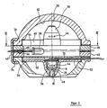
- FIG. 2 shows a section through an Ulbricht sphere, which contains two spherical halves 34, 36.
- Two intermediate rings 38, 40 are arranged between the aforementioned ball halves 34 and 36, the ball formed in this way being held together by means of clamping clips 42.
- This ball contains, in a known manner, two photoreceivers 44, 46, which are arranged in holding devices 48, 50.
- These holding devices 48 and 50 are constructed identically and for the sake of simplicity only the lower holding device 48 will be explained in more detail below.
- the holding device 48 is arranged by means of arms 52 in a groove 54 in the lower ball half 34.
- the aperture 8 with the conical aperture surface 10 is located coaxially to the axis of symmetry 30 within the receiving device 48.
- the photodetectors 44, 46 are cup-shaped for receiving - E-rwei- Chippings 56 is provided. These are preferably formed on the panel 8 made of matt black plastic and designed so that they can serve as a locking and fixing for the photoreceptor element 44 and 46, respectively.
- the photoreceivers 44 and 46 are arranged in the beam path behind the upper edge 28 of the diaphragm surface 10 in such a way that their light-sensitive surface is larger than the light beam penetrating through the diaphragm, ie the light-sensitive surface of the photoreceptor 44 and 46 must be so large and so arranged be that no rays that penetrate the aperture 8, get lost.
- a light source 58 designed as an LED is arranged between the arms 52 and 60 of the lower and upper receiving devices 48 and 50, respectively. Shielding of the light source 58 is effected in a simple manner by means of the arms 52, 60, so that no direct rays can reach the reference surfaces 4, 62, which are thus irradiated exclusively by diffuse light.
- the light source 58 is clamped with its current leads or legs between the intermediate rings 38 and 40, whereby a simple but nevertheless reliable locking of the light source 58 is achieved by means of the bead 66 and nose 68.
- a ball designed in this way can be produced and assembled from a few components and in a particularly simple manner, at the same time creating optimal conditions with regard to the lighting requirements.
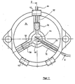
- FIG. 3 shows a section along section line III-III according to FIG. 2 and the arrangement of the lower holding device 48 in the center of the ball is readily apparent.
- the receiving device 48 is arranged in the ball half 34 by means of three arms 2 arranged in a star shape.
- the section plane of FIG. 2 is indicated by the line II-II.
- the light source 58 is arranged exactly above the one arm 52 and it can be seen that direct irradiation of the lower reference surface is prevented in this way.
- the light source 58 is fastened with its legs 64 in the manner explained above between the intermediate rings (not shown further here). From the photoreceiver 44, the power supply lines 70 are led to the outside above or within the leg 52.
- a further light source 58 is indicated by dash-dotted lines.
- the light sources 58 which may also be more than two light sources, preferably emit light of different wavelengths. By separately switching on or switching over to one or the other light source, the most varied measuring strips can thus be detected and evaluated with one and the same measuring device.
Landscapes
- Physics & Mathematics (AREA)
- Health & Medical Sciences (AREA)
- Life Sciences & Earth Sciences (AREA)
- Chemical & Material Sciences (AREA)
- Analytical Chemistry (AREA)
- Biochemistry (AREA)
- General Health & Medical Sciences (AREA)
- General Physics & Mathematics (AREA)
- Immunology (AREA)
- Pathology (AREA)
- Investigating Or Analysing Materials By Optical Means (AREA)
- Investigating Or Analysing Materials By The Use Of Chemical Reactions (AREA)
Abstract
Description
- Die Erfindung betrifft eine Vorrichtung zur reflexionsphotometrischen Messung des Reflexionsvermögens einer Bezugsfläche, die einen bestimmten, zur Auswertung heranzuziehenden Teil einer Objektfläche, insbesondere eines Testfeldes eines medizinischen Teststreifens bildet mit einer Lichtquelle zur Beleuchtung der Bezugsfläche bevorzugt mit diffusem Licht und einem Photoempfänger zum Empfang des von der Bezugsfläche reflektierten Lichts.
- In mr klinischen Chemie hat die Bestimmung medizinisch relevanter Bestandteile von Körperflüssigkeiten (Blut, Urin) mit Hilfe von Teststreifen zunehmend an Bedeutung gewonnen. Die untersuchten Inhaltsstoffe der Körperflüssigkeiten führen dabei zu charakteristischen Farbreaktionen auf den Testfeldern, welche visuell ausgewertet werden können, um eine qualitative Aussage zu erhalten. In neuerer Zeit hat darüberhinaus die quantitative Bestimmung medizinisch relevanter Parameter mit Hilfe von Teststreifen und entsprechenden Auswertegeräten zunehmend an Bedeutung gewonnen. Dabei werden . sowohl an die Teststreifen als auch an die Auswertegeräte sehr hohe Anforderungen gestellt, um eine befriedigende Meßgenauigkeit zu erreichen. Die vorliegende Erfindung richtet sich auf Maßnahmen zur Erhöhung der Genauigkeit der Geräte.
- Bei der Reflexionsphotometrie von Teststreifen mißt man die Gesamtreflexion, die sich aus dem diffusen Anteil und dem regulären Anteil (Spiegelreflexion) zusammensetzt. Um beide Anteile gemeinsam zu erfassen, wird das Testfeld entweder gezielt beleuchtet und die diffuse Reflexion gemessen oder es wird eine diffuse Beleuchtung vorgesehen, wobei dann das reflektierte Licht gezielt gemessen wird. Die vorliegende Erfindung richtet sich speziell auf den zweiten Fall, wobei bevorzugt für die diffuse Beleuchtung des Testfeldes des Teststreifens eine Ulbricht'sche Kugel verwendet wird.
- Bei solchermaßen aufgebauten Reflexionsphotometern ist es äußerst wichtig, daß die von dem Photoempfänger empfangenen Strahlen tatsächlich praktisch ausschließlich von demjenigen Teil einer Objektfläche, auf den sich die Messung beziehen soll und der hier als Bezugsfläche bezeichnet wird, ausgehen und nicht von anderen reflektierenden Objekten, die in dem Gerät von dem zur Messung verwendeten Licht getroffen werden, bzw. von anderen Störlichtquellen. Diese scheinbar einfach zu erfüllende Forderung verursacht erhebliche Probleme, wenn es, wie bei der reflexionsphotometrischen Auswertung von Teststreifen auf höchste Genauigkeit ankommt und darüberhinaus die bei derartigen Geräten zu beachtenden Randbedingungen berücksichtigt werden. Die Geräte sollen nämlich möglichst klein und handlich sein und in vielen Fällen mit-einer Batterie als Engergiequelle auskommen. Deswegen steht in der Regel nur eine geringe Lichtintensität zur Verfügung und es ist wesentlich, daß das von der Bezugsfläche reflektierte Licht möglichst ungehindert zum Photoempfänger gelangt, während jegliche Störstrahlung möglichst vollständig ausgeblendet wird.. Da die Geräte in großen Stückzahlen auch für die Auswertung durch Laien (insbesondere Diabetiker bei der Selbstkontrolle des Zuckerspiegels) hergestellt werden sollen, kommt es weiterhin darauf an, daß die photometrische Meßeinrichtung kostengünstig zu produzieren und möglichst einfach zu montieren ist, ohne daß die zu erreichende Meßgenaugikeit dadurch leidet. Insbesondere sollen sehr enge Toleranzen und aufwendige Justierschritte bei der Montage vermieden werden.
- Der Erfindung liegt daher die Aufgabe zugrunde, mit möglichst einfachen Mitteln eine Verbesserung der Meßgenauigkeit zu erreichen und insbesondere den Einfluß störender Randstrahlen, die nicht von der Bezugsfläche stammen, zu unterdrücken, wobei die Strahlen von der Bezugsfläche möglichst ungehindert zu dem Photoempfänger gelangen sollen. Dabei soll eine hohe Funktionssicherheit unter allen Betriebsbedingungen gewährleistet sein.
- Diese Aufgabe wird erfindungsgemäß bei einer Vorrichtung der eingangs bezeichneten Art dadurch gelöst, daß im Strahlengang zwischen Bezugsfläche und Photoempfänger eine Blende mit einer im wesentlichen in Form einer Kegelstumpfmantelfläche ausgebildeten Blendenfläche derart angeordnet ist, daß die Blendenfläche die Symmetrieachse des Strahlengangs über einen Teil von dessen Länge im wesentlichen symmetrisch umgibt, wobei die Blendenfläche eine absorbierende,der Symmetrieachse zugewandte Oberfläche hat und sich in einer solchen Weise zum Photoempfänger hin verjüngt, daß ihr oberer Rand einen kleineren Querschnitt als ihr unterer Rand 'umfaßt.
- Dadurch, daß sich die Blendenfläche der Blende über eine gewisse Strecke des Strahlenganges erstreckt, wobei ihre Querschnittsfläche von der Bezugsfläche zum Photoempfänger hin im wesentlichen stetig zunimmt, wird ein praktisch vollständiges Ausblenden störender Randstrahlen erreicht, ohne daß die Intensität des von der Bezugsfläche auf-den Photoempfänger auftreffenden Lichts wesentlich vermindert wird (lediglich die vom Rand der Bezugsfläche ausgehenden Strahlen werden entsprechend einer weiter unten erläuterten Bewertungskurve in vorteilhafter Weise geschwächt.
- Die ausgezeichnete Wirkung der erfindungsgemäßen Blendenkonstruktion beweist sich daran, daß beim Ausmessen einer total absorbierenden Bezugsfläche ohne weitere Korrekturmaßnahmen praktisch exakt das Remissionsvermögen Null gemessen wird. Praktische Versuche haben ergeben, daß die durch Streulicht verursachte Restreflexion bei einem solchen Experiment mit der erfindungsgemäßen Blende unter 0,05 liegt, während mit bekannten Blendenkonstruktionen lediglich 0,5 % Restreflexion erreicht werden. Damit werden die in den Fachkreisen bekannten Null-Punkt-Probleme mit einem überraschend geringen konstruktiven Aufwand gelöst.
- Die erfindungsgemäße Blendenkonstruktion kann in verschiedenerlei Weise variiert werden. Der Querschnitt des Kegelmantels in einer Ebene senkrecht zur Symmetrieachse des Strahlenganges ist bevorzugt kreisförmig, kann jedoch, wenn eine nicht-kreisförmige Bezugsfläche ausgemessen werden soll, auch eine andere Form, beispielsweise die einer Elypse oder eines Ovals haben. Die innere, dem Strahlengang zugewandte Oberfläche der Blendenfläche ist absorbierend, bevorzugt schwarz ausgebildet. Bevorzugt weist sie eine definierte Rauhigkeit von etwa 10 µm auf. Praktisch besonders vorteilhaft ist es, wenn das gesamte,die Blende beinhaltende Bauteil aus einem entsprechend strukturierten schwarzen Kunststoff besteht. Dabei ist es auch möglich, daß die Blendenfläche abgestuft ist, so daß ihre Begrenzungslinien in einem Längsschnitt parallel zur Symmetrieachse des Strahlenganges einen unstetigen stufenförmigen Verlauf haben. Voraussetzung für die Erreichung der erfindungsgemäßen Vorteile ist lediglich, daß die durch die Blendenfläche umfaßte Blendenöffnung sich in ihrer Gesamtheit vom Photoempfänger zur Bezugsfläche hin erweitert und dabei so gestaltet ist, daß in der weiter unten näher erläuterten Art und Weise in die Blendenöffnung einfallende und damit auf die Blendenfläche auftreffende Randstrahlen in einem solchen Winkel reflektiert werden, daß eventuell nicht absorbierte Anteile wiederholt auf die Blendenfläche auftreffen und sich dadurch totlaufen.
- 'Besonders bevorzugt ist die Blendenfläche derartig gestaltet, daß ihr oberer Rand, ihr unterer Rand und die Begrenzung der Bezugsfläche, deren Reflexionsvermögen zu bestimmen ist, näherungsweise auf einer Schar von Geraden liegen, die die Symmetrieachse an einem Punkt innerhalb der durch die Blendenfläche umfassten Blendenöffnung, also zwischen den durch den oberen und unteren Rand der Blendenfläche definierten Ebenen schneiden und die Symmetrieachse symmetrisch umgeben. Auf diese Weise wird eine besonders günstige Bewertung der Bezugsfläche erreicht, weil die in der Regel weniger homogenen Randzonen des Testfeldes-ausgeblendet werden und überwiegend die Strahlen aus der Mitte der Bezugsfläche zur Auswertung beitragen.
- Bevorzugt ist eine zweite Blende vorgesehen, welche die Bezugsfläche maskenartig umgibt. Sie hat eine im wesentlichen ebene oder zum Photoempfänger konkav gekrümmte absorbierende Blendenfläche. Durch diese zusätzliche Maßnahme werden die besonders kritischen Randstrahlen, die auf die kegelstumpfmantelförmige Blendenfläche unter flachen Winkel auftreffen, zusätzlich geschwächt. Die Öffnung der zweiten Blende umgibt aus praktischen Gründen nicht exakt den Rand der gewünschten Bezugsfläche, sondern der Radius der Begrenzung der öffnung der zweiten Blende ist größenordnungsmäßig 10 % größer als der jeweilige Radius des Randes der Bezugsfläche. Dadurch wird vermieden, daß bei den nicht ganz vermeidbaren Toleranzen der Bauteile ein Teil der Blendenfläche der zweiten Blende in die Bezugsfläche fällt und dadurch das Meßergebnis verfälscht wird.
- Für den erwähnten, besonders bevorzugten Anwendungsfall, bei dem die Bezugsfläche über eine Ulbricht'sche Kugel diffus beleuchtet wird, ist bevorzugt ein zweiter Photoempfänger zur Messung eines bekannten Referenzwertes an einer Referenzfläche mit bekanntem Reflexionsvermögen vorgesehen. Dabei dient bevorzugt ein Teil der inneren Oberfläche der Ulbricht'schen Kugel als Referenzfläche. In diesem Fall weisen gemäß bevorzugter Ausführungsform der Erfindung beide Photoempfänger vollkommen gleich ausgebildete und angeordnete Blendeneinrichtungen auf. Es wird somit bezüglich der Lichtquelle und/oder innerhalb der genannten Kugel eine symmetrische Anordnung von Photoempfängern, zugehörigen Blenden und Bezugsflächen gewährleistet.,, wodurch eine hohe Meßgenauigkeit erreicht wird. So wirken sich äußere Einflüsse, wie zum Beispiel Temperaturschwankungen, Alterungserscheinungen bezüglich der beiden Photoempfänger in gleicher Weise aus und insbesondere durch die gleiche Anordnung und Ausbildung der Blenden werden für die beiden Photoempfänger übereinstimmende Empfangsbedingungen geschaffen. Es ist ersichtlich, daß hierdurch das Langzeitverhalten der Meßeinrichtung sehr günstig wird.
- Dadurch, daß ein Teil der inneren Kugeloberfläche der Ulbricht'schen Kugel als Referenzfläche verwendet wird, ist kein besonderer, separater Standard als Bezugsfläche erforderlich, sondern ein Teil der inneren Kugeloberfläche selbst ist Referenzfläche. Die erfindungsgemäße Meßeinrichtung weist dabei ein besonders gutes Langzeitverhalten auf, da sich die übrige Kugeloberfläche im Laufe der Zeit, falls Änderungen auftreten, in der gleichen wie der als Referenzfläche verwendete Teil ändert. Demzufolge ändert sich die Intensität, mit der die . Bezugsfläche beleuchtet wird im gleichen Maße wie das Reflexionsvermögen der Referenzfläche und bei der zur Auswertung herangezogenen Quotientenbildung eliminieren sich beide Effekte.
- In einer bevorzugten Ausführungsform sind Blende und Photoempfänger jeweils in einer Aufnahmevorrichtung angeordnet, welche mittels sternförmig angeordneten Armen in der bevorzugt aus zwei Hälften bestehenden Kugel angeordnet sind. Auf diese vorteilhafte Weise wird zum einen die oben erläuterte symmetrische Anordnung der Blenden und Photoempfänger erreicht und zum anderen wird eine einfache und konstengünstige Herstellung der Meßeinrichtung gewährleistet. Weiterhin wird ohne besonderen Aufwand sichergestellt, daß die Bezugsflächen von dem diffusen Licht bestrahlt werden.
- Vorteilhaft ist die Lichtquelle zwischen zwei Armen von zwei Aufnahmevorrichtungen derart angeordnet, daß mittels der Arme eine direkte Bestrahlung der Bezugsflächen verhindert wird. Mit anderen Worten, die besagten Arme dienen-gleichzeitig auch zur Abschirmung des von der Lichtquelle direkt ausgestrahlten Lichtes, wobei zusätzliche Bauteile, insbesondere Blenden und ähnliches, vermieden werden.
- In einer bevorzugten Ausführungsform sind die Arme der Aufnahmevorrichtungen jeweils in Nuten der Kugelhälften gelagert. Es wird in einfacher Weise eine definierte und den Betriebsbedingungen gerecht werdende Lagerung und Befestigung der Photoempfänger mit den Blenden erreicht. Auch die Herstellung und Montage bereiten keine Schwierigkeiten, da die Aufnahmevorrichtungen bzw. deren Arme einfach in die genannten Nuten eingesetzt werden können.
- In einer bevorzugten Ausführungsform weist die Meßeinrichtung zwei im wesentlichen gleich ausgebildete Kugelhälften auf, zwischen welchen bevorzugt zwei Zwischenringe angeordnet sind, mittels welchen die bevorzugt als eine LED ausgebildete Lichtquelle gelagert ist. Hierfür sind die Stromzuführungen bzw. Beinchen der Lichtquelle einfach zwischen die Zwischenringe eingeklemmt, wobei zur Arretierung der eine Zwischenring eine Sicke aufweist, in welche eine entsprechende Nase des anderen Zwischenringes eingreift. Die Montage und der Zusammenbau einer derart ausgebildeten Kugel ist mit wenigen Handgriffen durchführbar und die Lichtquelle ist in einer definierten Lage in der Symmetrieebene zwischen den Kugelhälften angeordnet.
- Weitere Vorteile und erfindungswesentliche Merkmale ergeben sich aus dem nachfolgend anhand der Zeichnung näher erläuterten Ausführungsbeispiel. Es zeigen:
- Fig. 1 eine Prinzipdarstellung einer Meßeinrichtung mit Photoempfänger und zugeordneter kegelförmiger Blende,
- Fig. 2 einen Schnitt durch eine Ulbricht'sche Kugel mit zwei Photoempfängern und zugehörigen Blenden,
- Fig. 3 einen Schnitt entlang der Schnittlinie III-III gemäß Fig. 2.
- Aus der Prinzipdarstellung gemäß Fig. 1 ist ein Photoempfänger 2 ersichtlich, mittels welchem von einer Bezugsfläche 4 reflektiertes Licht erfaßt werden soll. Diese Bezugsfläche 4 ist ein bestimmter Teil der Oberfläche eines Testfeldes 6, in welchem bekannterweise chemische Reaktionen zwischen Inhaltsstoffen, einer Körperflüssigkeit (z.B. Urin, Blut) und auf dem Testfeld vorhandenen Reagentien erfolgen. Die infolge der chemischen Reaktionen eintretenden Farbveränderungen sollen mit dem Photoempfänger quantitativ erfaßt werden, wobei hier nicht weiter zu erläuternde elektronische Auswerteeinrichtungen vorgesehen sind.
- Zwischen dem Photoempfänger 2 und der Bezugsfläche 4 befindet sich eine Blende 8. Charakteristisch an der Konstruktion der Blende 8 ist, daß sie nicht an einer bestimmten Stelle den Strahlengang begrenzt, sondern daß sich die von der Blendenfläche 10 umfasste Blendenöffnung 9 über eine Länge, die in der Fig. 1 mit dem Bezugszeichen 16 bezeichnet ist, entlang dem Strahlengang erstreckt. In der Querschnittsdarstellung der Fig. 1.bilden die Schnittlinien der Blendenfläche zwei Geraden auf beiden Seiten der Symmetrieachse 30, die zugleich Symmetrieachse des Strahlengangs und der Blendenanordnung ist. Räumlich betrachtet bildet die Blendenfläche 10 die Mantelfläche eines Kegelstumpfes mit vorzugsweise, aber nicht notwendigerweise kreisförmigen Querschnitt. Der Kegelstumpf umgibt die Symmetrieachse über die Länge 16 symmetrisch. Die Blendenfläche hat auf der der Bezugsfläche 4 zugewandten Seite einen unteren Rand 26 und auf der dem Photoempfänger 2 zugewandten Seite einen oberen Rand 28.
- Die innere Oberfläche 11 der Blendenfläche 10 ist absorbierend, bevorzugt matt-schwarz ausgebildet. Aus Fig. 1 ist ohne weiteres ersichtlich, daß in die Blendenöffnung 9 eindringende Randstrahlen aufgrund der erfindungsgemäßen Blendenkonstruktion nicht zum Photoempfänger 2 gelangen können. Eingezeichnet sind die Randstrahlen 12 und 14. Obwohl die innere Oberfläche 11 der Blendenfläche 10 absorbierend ausgebildet ist, läßt sich in der Praxis nicht verhindern, daß ein Teil der jeweiligen Randstrahlen von der Oberfläche reflektiert wird. Für die Funktion der erfindungsgemäßen Blendenkonstruktion ist nun wesentlich, daß die Blendenfläche 10 so gestaltet ist, daß diese reflektierten Anteile von Randstrahlen derartig zurückgeworfen werden, daß sie wiederholt auf die der Symmetrieachse 30 zugewandte Oberfläche 11 der Blendenfläche 10 auftreffen. Dadurch laufen sich derartige Randstrahlen tot und werden praktisch vollständig eliminiert.
- Bei der in Fig. 1 dargestellten Ausführungsform befindet sich unmittelbar oberhalb der Bezugsfläche 4 eine zweite Blende 18, deren Blendenfläche 19 zum Photoempfänger hin konkav gekrümmt ist. Sie hat ebenfalls eine matt-schwarz ausgebildete Oberfläche 21. Die Blende 18 weist eine von dem Rand 20 umgebene Blendenöffnung auf, wobei zwischen dem Rand 20 und der Begrenzung 23 der Bezugsfläche 4 ein Abstand ist, der etwa 10 % des Radius der Bezugsfläche 4 beträgt.
- In der dargestellten Ausführungsform liegen der obere Rand 28 und der untere Rand 26 der Blendenfläche 10 sowie die Begrenzung 23 der Bezugsfläche 4 auf einer Schar von Geraden, wobei die in der Zeichenebene liegenden Geraden mit den Bezugszeichen 22 und 24 bezeichnet sind. Die Geraden schneiden sich alle in einem Punkt 25 der Symmetrieachse 30 innerhalb der von der Blendenfläche 10 umfassten Blendenöffnung 9. Die Länge 16 der Blende 8 ist bevorzugt mindestens so groß wie der größte Durchmesser des unteren Randes 26.
- Aufgrund der erfindungsgemäßen Anordnung und Zuordnung der Blenden 8 und 18 wird eine besonders günstige Bewertung der von der Bezugsfläche 4 reflektierten Strahlung erreicht. Die Bewertungskurve der Bezugsfläche ist im unteren Teil der Fig. 1 als Kurve 32 dargestellt, wobei ersichtlich ist, daß die Intensität I der zum Photoempfänger 2 gelangenden Strahlung am Rand der Bezugsfläche zur Mitte hin allmählich anwächst. Dies ist insofern günstig, als die Testfelder von Teststreifen häufig weniger homogene Randbereiche aufweisen, die bei der Auswertung eine geringere Bewertung erfahren sollen. Im mittleren Bereich verläuft die Bewertungskurve horizontal, d.h. die von der Bezugsfläche 4 ausgehende Strahlung wird praktisch ungehindert an den Photoempfänger 2 durchgelassen, so daß die volle Intensität der Strahlung genutzt wird.
- Fig. 2 zeigt einen Schnitt durch eine Ulbricht'sche Kugel, welche zwei Kugelhälften 34, 36 enthält. Zwischen den genannten Kugelhälften 34 und 36 sind zwei Zwischenringe 38, 40 angeordnet, wobei die derart gebildete Kugel mittels Spannklammern 42 zusammengehalten wird. Diese Kugel enthält in bekannter Weise zwei Photoempfänger 44, 46, welche in Aufnahmevorrichtungen 48, 50 angeordnet sind. Diese Aufnahmevorrichtungen 48 und 50 sind identisch aufgebaut und es soll der Einfachheit halber nachfolgend nur die untere Aufnahmevorrichtung 48 näher erläutert werden. Die Aufnahmevorrichtung 48 ist mittels Armen 52 in einer Nut 54 der unteren Kugelhälfte 34 angeordnet. Innerhalb der Aufnahmevorrichtung 48 befindet sich koaxial zur Symmetrieachse 30 die Blende 8 mit der kegelförmigen Blendenfläche 10.
- In der in Fig. 2 dargestellten Ausführungsform sind zur Aufnahme der Photoempfänger 44, 46 topfförmige-E-rwei- terungen 56 vorgesehen. Diese sind bevorzugt an der aus matt-schwarzem Kunststoff hergestellten Blende 8 ausgeformt und so gestaltet, daß sie als Arretierung und Fixierung für das Photoempfängerelement 44 bzw. 46 dienen können. Die Photoempfänger 44 und 46 sind derartig im Strahlengang hinter-dem oberen Rand 28 der Blendenfläche 10 angeordnet, daß ihre lichtempfindliche Fläche größer ist als der durch die Blende dringende Lichtstrahl, d.h. die lichtempfindliche Fläche des Photoempfängers 44 bzw. 46 muß so groß und so angeordnet sein, daß keine Strahlen, die die Blende 8 durchdringen, verloren gehen.
- Eine als LED ausgebildete Lichtquelle 58 ist zwischen den Armen 52 und 60 der unteren bzw. oberen Aufnahmevorrichtung 48 bzw. 50 angeordnet. Mittels der Arme 52, 60 wird in einfacher Weise eine Abschirmung der Lichtquelle 58 bewirkt, so daß keine direkten Strahlen zu den Bezugsflächen 4, 62 gelangen können, welche somit ausschließlich von diffusem Licht bestrahlt werden. Die Lichtquelle 58 ist mit ihren Stromzuführungen bzw. Beinchen zwischen die Zwischenringe 38 und 40 eingeklemmt, wobei mittels Sicke 66 und Nase 68 eine einfache und dennoch zuverlässige Arretierung der Lichtquelle 58 erreicht wird. Eine derart ausgebildete Kugel läßt sich aus wenigen Bauteilen und in besonders einfacher Weise herstellen und montieren, wobei zugleich optimale Bedingungen hinsichtlich der lichttechnischen Anforderungen geschaffen sind.
- Fig. 3 zeigt einen Schnitt entlang Schnittlinie III-III gemäß Fig. 2 und die Anordnung der unteren Aufnahmevorrichtung 48 in der Mitte der Kugel ist ohne weiteres ersichtlich. Die Aufnahmevorrichtung 48 ist mittels drei sternförmig angeordneten Armen 2 in der Kugelhälfte 34 angeordnet. Durch die Linie II-II ist die Schnittebene von Fig. 2 angedeutet. Die Lichtquelle 58 ist exakt oberhalb dem einen Arm 52 angeordnet und es ist ersichtlich, daß auf diese Weise eine direkte Bestrahlung der unteren Bezugsfläche verhindert wird. Die Lichtquelle 58 ist mit ihren Beinchen 64 in der oben erläuterten Weise zwischen den hier nicht weiter dargestellten Zwischenringen befestigt. Von dem Photoempfänger 44 werden die Stromzuführungen 70 über bzw. innerhalb des Beinchens 52 nach außen geführt. Strichpunktiert ist noch eine weitere Lichtquelle 58 angedeutet. Sofern diese Lichtquelle Licht mit der gleichen Wellenlänge wie die erste Lichtquelle ausstrahlt, kann somit in einfacher Weise eine Erhöhung der Lichtintensität erreicht werden, ohne daß hierzu eine besonders große Lichtquelle erforderlich ist. Bevorzugt strahlen die Lichtquellen 58, wobei es sich auch um mehr als zwei Lichtquellen handeln kann, Licht von verschiedenen Wellenlängen aus. Durch separates Einschalten bzw. Umschalten auf die eine oder andere Lichtquelle können somit mit ein und derselben Meßeinrichtung die unterschiedlichsten Meßstreifen erfaßt und ausgewertet werden.
Claims (10)
Priority Applications (1)
| Application Number | Priority Date | Filing Date | Title |
|---|---|---|---|
| AT82108380T ATE41234T1 (de) | 1981-09-30 | 1982-09-11 | Vorrichtung zur reflexionsphotometrischen messung. |
Applications Claiming Priority (2)
| Application Number | Priority Date | Filing Date | Title |
|---|---|---|---|
| DE3138878 | 1981-09-30 | ||
| DE19813138878 DE3138878A1 (de) | 1981-09-30 | 1981-09-30 | Messeinrichtung, insbesondere ulbricht'sche kugel |
Publications (2)
| Publication Number | Publication Date |
|---|---|
| EP0075766A1 true EP0075766A1 (de) | 1983-04-06 |
| EP0075766B1 EP0075766B1 (de) | 1989-03-08 |
Family
ID=6143031
Family Applications (1)
| Application Number | Title | Priority Date | Filing Date |
|---|---|---|---|
| EP82108380A Expired EP0075766B1 (de) | 1981-09-30 | 1982-09-11 | Vorrichtung zur reflexionsphotometrischen Messung |
Country Status (5)
| Country | Link |
|---|---|
| US (1) | US4523853A (de) |
| EP (1) | EP0075766B1 (de) |
| JP (1) | JPS5868644A (de) |
| AT (1) | ATE41234T1 (de) |
| DE (2) | DE3138878A1 (de) |
Cited By (10)
| Publication number | Priority date | Publication date | Assignee | Title |
|---|---|---|---|---|
| EP0154875A3 (en) * | 1984-03-02 | 1986-03-12 | Boehringer Mannheim Gmbh | Device for the determination of the diffuse surface reflection of a sample of small dimensions |
| EP0177861A3 (en) * | 1984-10-10 | 1986-07-23 | Miles Laboratories, Inc. | Readhead with reduced height sensitivity |
| EP0174186A3 (en) * | 1984-09-04 | 1987-07-29 | Eastman Kodak Company | Reflectometer |
| US4720372A (en) * | 1983-06-16 | 1988-01-19 | Boehringer Mannheim Gmbh | Device for the evaluation of a flat test carrier for the analytical determination of components of body fluids |
| EP0203388A3 (de) * | 1985-05-24 | 1989-01-18 | Erwin Sick GmbH Optik-Elektronik | Oberflächenbeschaffenheitsfeststellungs-Lichtabtastvorrichtung mit einem Lichtkonzentrator |
| DE3844104A1 (de) * | 1988-12-28 | 1990-07-05 | Boehringer Mannheim Gmbh | Testtraeger-analysesystem |
| EP0344645A3 (en) * | 1988-06-03 | 1990-08-16 | Firma Carl Zeiss | Device for measuring reflection |
| EP0394909A1 (de) * | 1989-04-28 | 1990-10-31 | Roche Diagnostics GmbH | Verfahren zur diffusen Beleuchtung einer Messfläche in einem Testträgeranalysegerät |
| GB2234586A (en) * | 1989-07-14 | 1991-02-06 | Ricoh Kk | Toner density sensing device for image forming equipment |
| EP0762111A1 (de) * | 1995-09-05 | 1997-03-12 | Bayer Corporation | Reflexionslesekopf für diffuses Licht |
Families Citing this family (27)
| Publication number | Priority date | Publication date | Assignee | Title |
|---|---|---|---|---|
| JPS5979841A (ja) * | 1982-10-29 | 1984-05-09 | Shimadzu Corp | 絶対反射率測定装置 |
| DE3406848A1 (de) * | 1984-02-22 | 1985-08-22 | OPTRONIK GmbH opto - elektronische - systeme, 1000 Berlin | Beleuchtungseinrichtung fuer die erzeugung einer diffusen lichtverteilung an der messoeffnung eines hohlkoerpers |
| US4755058A (en) * | 1984-06-19 | 1988-07-05 | Miles Laboratories, Inc. | Device and method for measuring light diffusely reflected from a nonuniform specimen |
| JPS6252438A (ja) * | 1985-08-30 | 1987-03-07 | Shimadzu Corp | 積分球式分光反射率測定装置 |
| US4935346A (en) | 1986-08-13 | 1990-06-19 | Lifescan, Inc. | Minimum procedure system for the determination of analytes |
| DE3630999A1 (de) * | 1986-09-12 | 1988-03-17 | Boehringer Mannheim Gmbh | Mehrschichtiger testtraeger |
| US7141212B2 (en) * | 1993-11-12 | 2006-11-28 | Inverness Medical Switzerland Gmbh | Reading devices and assay devices for use therewith |
| US5597532A (en) * | 1994-10-20 | 1997-01-28 | Connolly; James | Apparatus for determining substances contained in a body fluid |
| DE19619513C2 (de) * | 1996-05-14 | 2001-03-22 | Stoeckert Instr Gmbh | Vorrichtung für die Messung physiologischer Parameter von in einem extrakorporalen Kreislauf geführtem Blut |
| US6267722B1 (en) | 1998-02-03 | 2001-07-31 | Adeza Biomedical Corporation | Point of care diagnostic systems |
| US6394952B1 (en) | 1998-02-03 | 2002-05-28 | Adeza Biomedical Corporation | Point of care diagnostic systems |
| JP2002502980A (ja) * | 1998-02-10 | 2002-01-29 | イーワイ ラボラトリーズ インコーポレイテッド | 試料ホルダ起伏形状を補償し且つシステム・ノイズのロック除去を行う反射測定システム |
| US5995236A (en) | 1998-04-13 | 1999-11-30 | Mit Development Corporation | Blood fluid characteristics analysis instrument |
| USD434153S (en) * | 1998-04-20 | 2000-11-21 | Adeza Biomedical Corporation | Point of care analyte detector system |
| USD432244S (en) * | 1998-04-20 | 2000-10-17 | Adeza Biomedical Corporation | Device for encasing an assay test strip |
| US6458326B1 (en) | 1999-11-24 | 2002-10-01 | Home Diagnostics, Inc. | Protective test strip platform |
| US6525330B2 (en) | 2001-02-28 | 2003-02-25 | Home Diagnostics, Inc. | Method of strip insertion detection |
| US6541266B2 (en) | 2001-02-28 | 2003-04-01 | Home Diagnostics, Inc. | Method for determining concentration of an analyte in a test strip |
| US6562625B2 (en) | 2001-02-28 | 2003-05-13 | Home Diagnostics, Inc. | Distinguishing test types through spectral analysis |
| EP1459099A4 (de) * | 2001-12-27 | 2006-08-23 | Inverness Medical Switzerland | Neuartiges bauelement, system und verfahren zur fluoreszenzdetektion |
| RU2301408C2 (ru) * | 2002-12-30 | 2007-06-20 | Закрытое акционерное общество "СибНИИстрой" | Установка для определения общего коэффициента пропускания света оконных блоков и измерительный блок для нее |
| US7239394B2 (en) * | 2003-06-04 | 2007-07-03 | Inverness Medical Switzerland Gmbh | Early determination of assay results |
| US7315378B2 (en) * | 2003-06-04 | 2008-01-01 | Inverness Medical Switzerland Gmbh | Optical arrangement for assay reading device |
| US7317532B2 (en) * | 2003-06-04 | 2008-01-08 | Inverness Medical Switzerland Gmbh | Flow sensing for determination of assay results |
| GB2450351B (en) | 2007-06-20 | 2012-01-18 | Cozart Bioscience Ltd | Monitoring an Immunoassay |
| AU2014334502A1 (en) * | 2013-10-08 | 2016-05-05 | Djordje DIKIC | System, method and apparatus for performing colour matching |
| CN106574897B (zh) * | 2014-06-10 | 2020-02-14 | 赛诺菲-安万特德国有限公司 | 用于确定与表面反射特征相关的信息的设备 |
Citations (5)
| Publication number | Priority date | Publication date | Assignee | Title |
|---|---|---|---|---|
| US2280993A (en) * | 1940-12-05 | 1942-04-28 | American Cyanamid Co | Turbidimeter |
| DD110341A1 (de) * | 1974-02-21 | 1974-12-12 | ||
| DE2902776A1 (de) * | 1978-01-25 | 1979-08-02 | Kyoto Daiichi Kagaku Kk | Verfahren fuer das analysieren mit farbidentifizierungs-testpapier und eine vorrichtung zur durchfuehrung des verfahrens |
| US4232971A (en) * | 1978-03-23 | 1980-11-11 | Shigeru Suga | Integrating sphere type standard light source device |
| FR2466783A1 (fr) * | 1979-09-28 | 1981-04-10 | Thomson Csf | Procede de protection contre les reflexions intempestives d'un faisceau optique et dispositif destine a la mise en oeuvre de ce procede |
Family Cites Families (5)
| Publication number | Priority date | Publication date | Assignee | Title |
|---|---|---|---|---|
| US2358020A (en) * | 1940-08-31 | 1944-09-12 | Gen Motors Corp | Color analyzing device |
| US2688099A (en) * | 1949-09-14 | 1954-08-31 | Everett H Bickley | Scanning mechanism for color sorting machines |
| US3327583A (en) * | 1962-07-16 | 1967-06-27 | Lion Res Corp | Apparatus with diffusely reflecting hollow housing for measuring absolute reflectivity of a surface and the like |
| DE2834983C3 (de) * | 1978-08-10 | 1981-09-03 | Vladimir Dr.-Ing. 5100 Aachen Blazek | Meßkopf für Beleuchtungsstärke-Meßgeräte |
| DD147001A1 (de) * | 1979-10-31 | 1981-03-11 | Ludwig W Wieczorek | Strahlungsenergie-und-leistungsmessgeraet |
-
1981
- 1981-09-30 DE DE19813138878 patent/DE3138878A1/de not_active Withdrawn
-
1982
- 1982-08-31 US US06/413,292 patent/US4523853A/en not_active Expired - Lifetime
- 1982-09-11 DE DE8282108380T patent/DE3279511D1/de not_active Expired
- 1982-09-11 AT AT82108380T patent/ATE41234T1/de not_active IP Right Cessation
- 1982-09-11 EP EP82108380A patent/EP0075766B1/de not_active Expired
- 1982-09-17 JP JP57161070A patent/JPS5868644A/ja active Granted
Patent Citations (5)
| Publication number | Priority date | Publication date | Assignee | Title |
|---|---|---|---|---|
| US2280993A (en) * | 1940-12-05 | 1942-04-28 | American Cyanamid Co | Turbidimeter |
| DD110341A1 (de) * | 1974-02-21 | 1974-12-12 | ||
| DE2902776A1 (de) * | 1978-01-25 | 1979-08-02 | Kyoto Daiichi Kagaku Kk | Verfahren fuer das analysieren mit farbidentifizierungs-testpapier und eine vorrichtung zur durchfuehrung des verfahrens |
| US4232971A (en) * | 1978-03-23 | 1980-11-11 | Shigeru Suga | Integrating sphere type standard light source device |
| FR2466783A1 (fr) * | 1979-09-28 | 1981-04-10 | Thomson Csf | Procede de protection contre les reflexions intempestives d'un faisceau optique et dispositif destine a la mise en oeuvre de ce procede |
Cited By (13)
| Publication number | Priority date | Publication date | Assignee | Title |
|---|---|---|---|---|
| US4720372A (en) * | 1983-06-16 | 1988-01-19 | Boehringer Mannheim Gmbh | Device for the evaluation of a flat test carrier for the analytical determination of components of body fluids |
| US4676653A (en) * | 1984-03-02 | 1987-06-30 | Boehringer Mannheim Gmbh | Apparatus for determining the diffuse reflectivity of a sample surface of small dimensions |
| EP0154875A3 (en) * | 1984-03-02 | 1986-03-12 | Boehringer Mannheim Gmbh | Device for the determination of the diffuse surface reflection of a sample of small dimensions |
| EP0174186A3 (en) * | 1984-09-04 | 1987-07-29 | Eastman Kodak Company | Reflectometer |
| EP0177861A3 (en) * | 1984-10-10 | 1986-07-23 | Miles Laboratories, Inc. | Readhead with reduced height sensitivity |
| EP0203388A3 (de) * | 1985-05-24 | 1989-01-18 | Erwin Sick GmbH Optik-Elektronik | Oberflächenbeschaffenheitsfeststellungs-Lichtabtastvorrichtung mit einem Lichtkonzentrator |
| EP0344645A3 (en) * | 1988-06-03 | 1990-08-16 | Firma Carl Zeiss | Device for measuring reflection |
| DE3844104A1 (de) * | 1988-12-28 | 1990-07-05 | Boehringer Mannheim Gmbh | Testtraeger-analysesystem |
| EP0394909A1 (de) * | 1989-04-28 | 1990-10-31 | Roche Diagnostics GmbH | Verfahren zur diffusen Beleuchtung einer Messfläche in einem Testträgeranalysegerät |
| US5131756A (en) * | 1989-04-28 | 1992-07-21 | Boehringer Mannheim Gmbh | Test carrier analysis device |
| GB2234586A (en) * | 1989-07-14 | 1991-02-06 | Ricoh Kk | Toner density sensing device for image forming equipment |
| GB2234586B (en) * | 1989-07-14 | 1993-12-01 | Ricoh Kk | Toner density sensing device for image forming equipment |
| EP0762111A1 (de) * | 1995-09-05 | 1997-03-12 | Bayer Corporation | Reflexionslesekopf für diffuses Licht |
Also Published As
| Publication number | Publication date |
|---|---|
| JPS5868644A (ja) | 1983-04-23 |
| ATE41234T1 (de) | 1989-03-15 |
| DE3138878A1 (de) | 1983-04-14 |
| EP0075766B1 (de) | 1989-03-08 |
| JPS6323495B2 (de) | 1988-05-17 |
| DE3279511D1 (en) | 1989-04-13 |
| US4523853A (en) | 1985-06-18 |
Similar Documents
| Publication | Publication Date | Title |
|---|---|---|
| EP0075766B1 (de) | Vorrichtung zur reflexionsphotometrischen Messung | |
| DE2812872C2 (de) | Spektralphotometer | |
| EP0154875B1 (de) | Gerät zur Bestimmung des diffusen Reflexionsvermögens einer Probenfläche kleiner Abmessungen | |
| DE2949197C2 (de) | Integrationskugel-Trübungsmesser | |
| DE2049716C3 (de) | Verfahren und Vorrichtung zur Absorptionsmessung im Blut | |
| DE2951459C2 (de) | Optische Anordnung für einen Rauchmelder nach dem Lichtstreuungsprinzip | |
| DE69636403T2 (de) | Spektrometrie und optisches Messverfahren und Vorrichtung | |
| DE2636420C3 (de) | Vorrichtung zur Verwendung be i der Farbmessung an flächenhaften Proben | |
| DE2046492C3 (de) | Rauchmelder | |
| DE4236803C2 (de) | Mikroskop für mikroskopisch zu untersuchende Amplituden- und/ oder Phasenobjekte | |
| DE2828190A1 (de) | Streulicht-rauchfuehler | |
| DE60211986T2 (de) | Verfahren und Vorrichtung zur Messung der Lichtdurchlässigkeit von Linsen | |
| DE3685945T2 (de) | Analysiergeraet. | |
| DE112006003778B4 (de) | Optische Messvorrichtung | |
| DE19700379B4 (de) | Verfahren zur Einstellung der optischen Achse einer Meßvorrichtung zur Messung der Teilchengrößenverteilung mittels des Streueffekts | |
| DE102018105904A1 (de) | Sensorvorrichtung | |
| EP0394909B1 (de) | Verfahren zur diffusen Beleuchtung einer Messfläche in einem Testträgeranalysegerät | |
| EP0823626B1 (de) | Vorrichtung und Verfahren zum Messen eines Teilchenstromes in einem Fluid | |
| DE2653230A1 (de) | Strahlungsdetektor | |
| EP0864083A1 (de) | Nephelometer | |
| DE69114069T2 (de) | Optischer Detektor für Ausrüstung zum Messen einer Substanz in einer Flüssigkeit. | |
| DE102017101102B3 (de) | Verfahren und Koordinatenmessgerät zur Messung von optischen Eigenschaften eines optischen Filters | |
| DE3517650A1 (de) | Integrierende empfangseinrichtung fuer laserstrahlung | |
| EP0209659A2 (de) | Tropfendetektor | |
| DE3000033A1 (de) | Verfahren und vorrichtung zum messen der richtungsverteilung der von einem teilchen zurueckgestrahlten strahlungsenergie zur teilchencharakterisierung |
Legal Events
| Date | Code | Title | Description |
|---|---|---|---|
| PUAI | Public reference made under article 153(3) epc to a published international application that has entered the european phase |
Free format text: ORIGINAL CODE: 0009012 |
|
| 17P | Request for examination filed |
Effective date: 19820911 |
|
| AK | Designated contracting states |
Designated state(s): AT BE CH DE FR GB IT LI LU NL SE |
|
| GRAA | (expected) grant |
Free format text: ORIGINAL CODE: 0009210 |
|
| AK | Designated contracting states |
Kind code of ref document: B1 Designated state(s): AT BE CH DE FR GB IT LI LU NL SE |
|
| REF | Corresponds to: |
Ref document number: 41234 Country of ref document: AT Date of ref document: 19890315 Kind code of ref document: T |
|
| ITF | It: translation for a ep patent filed | ||
| REF | Corresponds to: |
Ref document number: 3279511 Country of ref document: DE Date of ref document: 19890413 |
|
| ET | Fr: translation filed | ||
| GBT | Gb: translation of ep patent filed (gb section 77(6)(a)/1977) | ||
| PLBE | No opposition filed within time limit |
Free format text: ORIGINAL CODE: 0009261 |
|
| STAA | Information on the status of an ep patent application or granted ep patent |
Free format text: STATUS: NO OPPOSITION FILED WITHIN TIME LIMIT |
|
| 26N | No opposition filed | ||
| ITTA | It: last paid annual fee | ||
| EPTA | Lu: last paid annual fee | ||
| EAL | Se: european patent in force in sweden |
Ref document number: 82108380.5 |
|
| PGFP | Annual fee paid to national office [announced via postgrant information from national office to epo] |
Ref country code: DE Payment date: 20000904 Year of fee payment: 19 |
|
| PGFP | Annual fee paid to national office [announced via postgrant information from national office to epo] |
Ref country code: SE Payment date: 20000906 Year of fee payment: 19 Ref country code: GB Payment date: 20000906 Year of fee payment: 19 |
|
| PGFP | Annual fee paid to national office [announced via postgrant information from national office to epo] |
Ref country code: FR Payment date: 20000912 Year of fee payment: 19 |
|
| PGFP | Annual fee paid to national office [announced via postgrant information from national office to epo] |
Ref country code: AT Payment date: 20000913 Year of fee payment: 19 |
|
| PGFP | Annual fee paid to national office [announced via postgrant information from national office to epo] |
Ref country code: LU Payment date: 20000915 Year of fee payment: 19 |
|
| PGFP | Annual fee paid to national office [announced via postgrant information from national office to epo] |
Ref country code: CH Payment date: 20000922 Year of fee payment: 19 |
|
| PGFP | Annual fee paid to national office [announced via postgrant information from national office to epo] |
Ref country code: NL Payment date: 20000928 Year of fee payment: 19 |
|
| PGFP | Annual fee paid to national office [announced via postgrant information from national office to epo] |
Ref country code: BE Payment date: 20001117 Year of fee payment: 19 |
|
| PG25 | Lapsed in a contracting state [announced via postgrant information from national office to epo] |
Ref country code: LU Free format text: LAPSE BECAUSE OF NON-PAYMENT OF DUE FEES Effective date: 20010911 Ref country code: GB Free format text: LAPSE BECAUSE OF NON-PAYMENT OF DUE FEES Effective date: 20010911 Ref country code: AT Free format text: LAPSE BECAUSE OF NON-PAYMENT OF DUE FEES Effective date: 20010911 |
|
| PG25 | Lapsed in a contracting state [announced via postgrant information from national office to epo] |
Ref country code: SE Free format text: LAPSE BECAUSE OF NON-PAYMENT OF DUE FEES Effective date: 20010912 |
|
| PG25 | Lapsed in a contracting state [announced via postgrant information from national office to epo] |
Ref country code: LI Free format text: LAPSE BECAUSE OF NON-PAYMENT OF DUE FEES Effective date: 20010930 Ref country code: CH Free format text: LAPSE BECAUSE OF NON-PAYMENT OF DUE FEES Effective date: 20010930 Ref country code: BE Free format text: LAPSE BECAUSE OF NON-PAYMENT OF DUE FEES Effective date: 20010930 |
|
| BERE | Be: lapsed |
Owner name: BOEHRINGER MANNHEIM G.M.B.H. Effective date: 20010930 |
|
| PG25 | Lapsed in a contracting state [announced via postgrant information from national office to epo] |
Ref country code: NL Free format text: LAPSE BECAUSE OF NON-PAYMENT OF DUE FEES Effective date: 20020401 |
|
| GBPC | Gb: european patent ceased through non-payment of renewal fee |
Effective date: 20010911 |
|
| PG25 | Lapsed in a contracting state [announced via postgrant information from national office to epo] |
Ref country code: DE Free format text: LAPSE BECAUSE OF NON-PAYMENT OF DUE FEES Effective date: 20020501 |
|
| EUG | Se: european patent has lapsed |
Ref document number: 82108380.5 |
|
| REG | Reference to a national code |
Ref country code: CH Ref legal event code: PL |
|
| PG25 | Lapsed in a contracting state [announced via postgrant information from national office to epo] |
Ref country code: FR Free format text: LAPSE BECAUSE OF NON-PAYMENT OF DUE FEES Effective date: 20020531 |
|
| NLV4 | Nl: lapsed or anulled due to non-payment of the annual fee |
Effective date: 20020401 |
|
| REG | Reference to a national code |
Ref country code: FR Ref legal event code: ST |
|
| NLV4 | Nl: lapsed or anulled due to non-payment of the annual fee |
Effective date: 20020401 |
|
| APAH | Appeal reference modified |
Free format text: ORIGINAL CODE: EPIDOSCREFNO |