EP0075923A2 - Antriebsvorrichtung eines linear folgenden Abtastarms eines Plattenspielers - Google Patents
Antriebsvorrichtung eines linear folgenden Abtastarms eines Plattenspielers Download PDFInfo
- Publication number
- EP0075923A2 EP0075923A2 EP82108954A EP82108954A EP0075923A2 EP 0075923 A2 EP0075923 A2 EP 0075923A2 EP 82108954 A EP82108954 A EP 82108954A EP 82108954 A EP82108954 A EP 82108954A EP 0075923 A2 EP0075923 A2 EP 0075923A2
- Authority
- EP
- European Patent Office
- Prior art keywords
- arm
- error angle
- tracking
- tracking error
- microprocessor
- Prior art date
- Legal status (The legal status is an assumption and is not a legal conclusion. Google has not performed a legal analysis and makes no representation as to the accuracy of the status listed.)
- Granted
Links
Images



Classifications
-
- G—PHYSICS
- G11—INFORMATION STORAGE
- G11B—INFORMATION STORAGE BASED ON RELATIVE MOVEMENT BETWEEN RECORD CARRIER AND TRANSDUCER
- G11B3/00—Recording by mechanical cutting, deforming or pressing, e.g. of grooves or pits; Reproducing by mechanical sensing; Record carriers therefor
- G11B3/02—Arrangements of heads
- G11B3/10—Arranging, supporting, or driving of heads or of transducers relatively to record carriers
- G11B3/34—Driving or guiding during transducing operation
- G11B3/38—Guiding, e.g. constructions or arrangements providing linear or other special tracking characteristics
-
- G—PHYSICS
- G11—INFORMATION STORAGE
- G11B—INFORMATION STORAGE BASED ON RELATIVE MOVEMENT BETWEEN RECORD CARRIER AND TRANSDUCER
- G11B21/00—Head arrangements not specific to the method of recording or reproducing
- G11B21/02—Driving or moving of heads
- G11B21/04—Automatic feed mechanism producing a progressive transducing traverse of the head in a direction which cuts across the direction of travel of the recording medium, e.g. helical scan, e.g. by lead-screw
-
- G—PHYSICS
- G11—INFORMATION STORAGE
- G11B—INFORMATION STORAGE BASED ON RELATIVE MOVEMENT BETWEEN RECORD CARRIER AND TRANSDUCER
- G11B21/00—Head arrangements not specific to the method of recording or reproducing
- G11B21/02—Driving or moving of heads
- G11B21/04—Automatic feed mechanism producing a progressive transducing traverse of the head in a direction which cuts across the direction of travel of the recording medium, e.g. helical scan, e.g. by lead-screw
- G11B21/06—Automatic feed mechanism producing a progressive transducing traverse of the head in a direction which cuts across the direction of travel of the recording medium, e.g. helical scan, e.g. by lead-screw the record carrier having mechanical means to ensure traverse movement of the head, e.g. grooves
Definitions
- the present invention relates generally to an apparatus for controlling a linear tracking arm in a linear tracking type record player or the like.
- the present invention concerns a linear tracking arm control system in which a microcomputer is made use of for performing servo-control in such a manner that a tracking error angle remains constantly zero, with a simplified circuit arrangement which nevertheless assures stabilized servo-control characteristics.
- the record player of a so-called linear tracking type in which a tone arm is linearly displaced in the direction radially of a record disc in playback operation has been increasingly used.
- a needle mounted at a free front end of the tone arm and an arm base adapted to support the tone arm at the rear end thereof are located on a line extending tangentially to a circular tone groove formed in the record disc.
- the needle is caused to follow the leading movement of the base arm sometimes with difficulty or inversely the arm base portion is caused to follow the tracking movement of the needle under the influence of frictional resistances between the needle and the record disc on one hand and between the arm base portion and a guide member therefor on the other hand.
- the tone arm is compelled to move with a certain angle to the tangential direction of the tone groove. This angle is referred to as the tracking error angle.
- Fig. 1 of the accompanying drawings shows schematically a typical example of the hitherto known systems for controlling the tracking movement of the tone arm.
- a tracking error angle produced upon movement of the cartridge la mounted at the free front end of a tone arm 1 is detected by a sensor 2 and, after having been amplified through a differential amplifier 3, supplied to a motor drive circuit 5 by way of a filter 4 having an appropriate transfer function, whereby the arm base 7 is caused to move in the direction to cancel out the tracking error angle by a motor 6 which is driven by the motor drive circuit 5.
- a reference voltage V 1 applied to the reference input of the differential amplifier 3 is so adjusted as to be equal to the voltage derived from the output of the sensor 2 when the tracking error angle of the tone arm 1 is zero.
- the serve-control system mentioned above exhibits complicated mechanical resonance characteristics ascribable to the inherent mechanical arrangement and requires the filter circuit 4 imparted with correspondingly complicated filter characteristic in order to attain the stabilized servo-control characteristic. Consequently, implementation of this servo-control system by electronic components or circuitries will require a large number of circuit elements, involving high expenditure.
- the output characteristic of the sensor 2 for detecting the tracking error angle undergoes variations as time elapses.
- the output of the sensor 2 produced when the tracking error angle is zero becomes different from the reference voltage V 1 applied to the reference input of the differential amplifier 3, resulting in that an offset error angle is produced to make it impossible or difficult to obtain the true tracking error angle, giving rise to another problem.
- a trace speed detecting circuit 9 for detecting that the tone arm has been moved to the end of the record groove.
- This circuit 9 serves to detect the tracing or tracking speed of the tone arm 1 and convert the latter into a corresponding voltage which is then supplied to a logic circuit 10 to be compared with a reference value set internally in the logic circuit 10.
- the tracing speed of the tone arm is relatively low so long as the needle point is tracing or tracking the tone groove. However, no sooner the needle point has entered a lead-out groove formed in the vicinity of the center of the record disc from the tone groove than the trace speed is steeply increased.
- a return signal is produced for controlling the motor drive circuit 5 to lift and return the tone arm to the rest or starting position.
- the return signal may be produced to reset the tone arm to the rest position even in the cource of tracing the tone groove, when the tracing speed is instantaneously increased due to possible eccentricity of the record disc.
- a linear tracking arm control system in which the tracking error angle of a linear tracking arm is detected to produce a corresponding electric signal, which is then supplied to a microprocessor to derive a servo-control signal which can cancel out the tracking error angle.
- a complicated transfer function inclusive of non-linear components can be easily realized by making use of inherent functions of the microprocessor such as arithmetic operation, storage capability, decision making function and the like, whereby stable servo-control characteristics can be attained.
- a linear tracking arm control system in which the offset error angle of the linear tracking arm is previously written and stored in a memory incorporated in the microprocessor every time playback operation is to be effected, wherein the adjustment of the offset error angle is rendered unnecessary by comparing the angle value stored in the memory with the actual tracking error angle produced in the course of playback operation, while assuring insusceptibility to the influence of the offset error angle due to the changes in the characteristic of the sensor as possibly brought about as time elapses.
- the offset error angle of the tone arm is newly set upon every playback operation to allow the preset offset error angle to be compared with the actual tracking error angle.
- the tone arm can trace the groove with the correct offset angle being maintained and without being subjected to the influence of the change in the sensor characteristic as brought about as a function of age, whereby the tracking or tracking performance of the tone arm is significantly improved, to an advantage.
- a linear tracking arm control system in which position detector means for converting the movement or instantaneous position of the arm into a series of position pulses to detect that the arm has been moved to the end position of a record disc, by counting the position pulses by means of a pulse counter for a predetermined time interval.
- the arm return signal is generated.
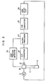
- Fig. 2 which shows a linear tracking arm control system according to an embodiment of the present invention in which the transfer function of an arm servo-control loop is generated by a microprocessor, a tracking error angle produced as a cartridge lla mounted on a tip end of a tone arm is moved is detected by a sensor 12 whose analogue output signal is converted into a corresponding digital signal by an analogue-to-digital or A/D converter 13 to be inputted to the microprocessor 14.
- the digital signal or data thus inputted is arithmetically processed by the microprocessor 14 to produce a driving pulse signal which is then converted into a corresponding analogue signal by a D/A converter 15 to be utilized for rotating a motor 17 through an arm drive circuit 16 for causing an arm base 18 to be displaced.
- the instantaneous position of the tone arm 11 is detected by an arm position detector 19.
- the transfer function of the servo system can be previously made known through experiments.
- the transfer function exhibits extremely complicated non-linear characteristic ascribable to mechanical elements constituting parts of the servo-control mechanism.
- the lead (or lag) quantity of the tone arm at a given instant is determined on the basis of pulse duration or width of the pulse signal supplied from the A/D converter 13 at that instant in accordance with a program stored in the microprocessor 14, and that the servo output quantity required for cancelling out the lead (or lag) is arithmetically determined on the basis of data stored in the memory of the microprocessor 14 to thereby produce at any instant the correct servo output quantity for cancelling out accurately the lead (or lag) of the tone arm.
- a minute change of the transfer function can be finely regulated by modifying the program only a bit.
- Fig. 3 shows in more concrete a linear tracking arm control system according to a first embodiment of the invention.
- the sensor 12 is composed of a photocoupler 20 constituted by a light emitting element and a light receiving element disposed in opposition to each other with a distance therebetween and a shutter member 21 swingable into the space defined between the paired elements of the photocoupler 20 in compliance with the swing movement of the tone arm 11.
- the A/D converter 13 is composed of transistors Q 1 and Q 2 , a resistor R 1 and a capacitor C 1 .
- FIG. 15/16 Broken line blocks attached with the reference numerals 15/16 represent motor drive circuits composed of operational amplifiers 22 and 23, resistors R 2 , R 3 and R 4 , R5 and capacitors C 2 and C 3' respectively.
- Each of the motor drive circuits exhibits a low pass characteristic and serves for the function which corresponds to those of the D/A converter 15 and the arm drive circuit 16 shown in Fig. 2.
- an analogue voltage produced by the sensor 12 in proportion to the tracking error angle defined hereinbefore is applied to the base of the transistor Q 2 to cause the collector current I 1 thereof to be varied.
- the tracking error angle can then be given in terms of a time taken for the collector potential of the transistor Q 2 to attain a predetermined reference voltage.
- a pulse signal of which width or duration varies in proportion to the tracking error angle.
- This pulse signal is supplied to the microprocessor 14 to be processed in accordance with a program stored in the microprocessor for producing the servo output signal which can cancel out the tracking error angle.
- the output signal from the microprocessor 14 is of course utilized for correspondingly controlling the motor 17 through the D/A converter/arm drive circuits 15/16, resulting in that the arm base 18 is displaced by the motor 17 to compensate the tracking error angle.
- control circuit can be realized inexpensively in a much simplified manner by using the A/D converter 13 which is capable of varying the pulse width of a pulse signal in accordance with the voltage signal representative of the tracking error angle, as is the case of the embodiment of the invention described above.
- the tracking error angle of the linearly driven tone arm is detected to thereby produce a corresponding electric signal which is then supplied to the microprocessor to be so processed as to produce as the output of the microprocessor the servo output signal for compensating or cancelling out the tracking error angle.
- the complex transfer function inclusive of non-linear components can be easily realized by making use of the arithmetic function, storage function and the decision making function which are inherent to the microprocessor, whereby the stabilized servo characteristic can be attained.
- the output characteristic of the sensor 12 which can be originally represented by a curve A shown in Fig. 4 will be changed to the characteristic represented by a curve B shown in the same figure as a function of time lapse, whereby the sensor output voltage V 0 corresponding to the zero offset angle of the tone arm 11 is changed to a sensor output level V o '.
- the sensor 11 produces the output signal (V o ') even when the offset error angle of the tone arm is zero to thereby cause the tone arm to be displaced through the arm driving motor 17, resulting in that the so-called offset error angle is generated to impede the tracking performance of the tone arm 11.
- low pass filters each denoted by reference numerals 25 and 25' and having the substantially same construction as the circuits 15 and 16 shown in Fig. 3 are connected to output terminals O ⁇ and O 1 , respectively, of the microprocessor 14 to linearize the offset error angle signals produced from these output terminals.
- driver circuits denoted by reference numerals 26 and 26' and composed of transistors Q 3 and Q 4 and resistors R 8 and R 9 , respectively, are connected to output terminals O 2 and O 3 of the microprocessor 14, respectively, so that the output signals making appearance at the output terminals O 2 and 0 3 of the microprocessor 14 are applied to the bases of the transistors Q 3 and Q 4 , respectively, to thereby control the driving voltage applied to the motor 17.
- the tone arm 11 is provided with the cartridge lla and a balancing weight 27 at the front and the rear end thereof, respectively, and is supported by an arm supporting mechanism 28 at an intermediate portion so as to be rotatable horizontally and vertically.
- the tone arm 11 is provided with a V-like projection llb at the lower surface.
- the projection llb is adapted to engage in a V-like groove 30a formed in an upper surface of a lift bar 20 which is adapted to be reciprocately moved by a cueing plunger 29.
- the microprocessor 14 is adapted to execute a plurality of main routines illustrated in Fig. 8 and a subroutine illustrated in Fig. 9.
- the main routines include an initializing main routine 31, a standby main routine 32, a start main routine 33 and a play main routine 34.
- initial values are set in a random access memory of the microprocessor in response to the start command, which are followed by setting of initial states.
- standby main routine 32 which follows the initializing main routine 31, reading of data inputted by key operation is effected, and it is determined whether or not the start key is actuated. Unless the start key is actuated, the reading of the key input is again executed.
- the execution proceeds to the start main routine, in which a pre-offset angle of the tone arm 11 upon lifting thereof which will be defined hereinafter is read in. Subsequently, the size of a record to be played is detected and the number of rotations is set. Next, it is determined whether or not the tone arm is in the lead-in position of the record. Unless the tone arm is not in the lead-in position, the tone arm is displaced in the forward or inward direction and it is again checked whether or not the tone arm is at the lead-in position. This process is repeated until it is decided that the tone arm is at the lead-in position of the record.
- the offset servo control is activated and it is determined whether or not the tone arm has come to the final position of the record. If the tone arm is not at the final end position of the record, activation of the offset servo control is continued. On the other hand, when it is detected that the tone arm is at the final end position, return is made to the initializing main routine 31 described above. On the other hand, in the subroutine illustrated in Fig. 9, detection of a pre-offset error angle is initiated in response to a start command. After lapse of a predetermined standby time, data of the pre-offset error angle employed in the preceding playing operation is cleared and a new pre-offset error angle is set.
- pre-offset error angle it is determined whether or not a pre-offset error angle is present or not. If the pre-offset error angle is absent, detection of the pre-offset error angle is terminated. Otherwise, data of the pre-offset error angle is loaded into the pre-offset error angle counter, which is followed by determination as to whether the contents of the pre-offset error angle counter has attained a predetermined value. If the result of the decision is negative, the process of loading the pre-offset error angle data into the pre-offset error angle counter is repeated until the predetermined value has been attained.
- the microprocessor 14 includes a memory for storing the output value of the sensor 12.
- Data of the offset angle of the tone arm 11 corresponding to the zero offset angle of the tone arm that is, the output value of the sensor 12 at the time when the tone arm 11 is lifted up with the V-like projection 116 of the tone arm engaging in the V-like groove 30a of the lift bar 30, is stored in the memory as the pre-offset angle data mentioned hereinbefore.
- the offset error angle of the tone arm is detected by the sensor 12 and converted into a corresponding voltage which is then converted into a corresponding time duration or a pulse having a corresponding width by means of the A/D converter 13, as described hereinbefore in conjunction with Fig. 3.
- the data of time duration thus obtained is inputted to the microprocessor 14 which arithmetically determines magnitude of the offset angle from the time duration data and outputs the corresponding digital signal.
- the digital signal is caused to pass through the low pass filter 25 to be converted into a corresponding DC voltage which is applied to the drive circuit 26 for driving the motor 17.
- the output of the sensor 12 corresponding to the zero offset error angle 3 f the tone arm 11 (this output corresponds to the pre-offset error angle mentioned hereinbefore) is converted into a pulse signal having a corresponding time duration or pulse width by the A/D converter 13 and stored in the memory of the microprocessor 14.
- the storing operation of the pre-offset angle is always effected in precedence to the starting of the playback operation, whereby the old data used in the preceding playback operation is replaced by new data for the succeeding playback operation.
- the output signal from the sensor 12 is converted into the pulse signal having a corresponding pulse duration by the A/D converter 13.
- the offset error angle data thus determined by the microprocessor on the basis of the pulse duration is compared with the pre-offset error angle data.
- the microprocessor 14 supplies an output signal to the filter 25 to control the arm driving motor 17 through the drive circuit 25 so that the tracking error angle becomes zero.
- the adjustment of the pre-offset error angle is made unnecessary by virtue of the feature of the invention that the pre-offset error angle is previously stored and compared with the detected error angle in the course of the playback operation. Further, since the pre-offset error angle is always newly stored or updated in precedence to every playback operation, no degradation will occur in the tracing performance of the tone arm during the playback operation even if the output of the sensor should be changed due to deterioration of the sensor characteristic.
- the pre-offset error angle is stored in the memory of the microprocessor after the A/D conversion.
- the pre-offset error angle may be directly written in an analogue memory.
- a reference numeral 35 denotes a photocoupler of the structure similar to that of the photocoupler 20 which includes a slit disc 36 adapted to be driven by the motor 17 so that at least the peripheral portion of the disc having a plurality of radial slits formed therein passes through a space defined between the light emitting element and the light receiving element of the photocoupler 35.
- An arm position detector 19 for detecting the instantaneous positon of the tone arm 11 (also refer to Fig. 2) in the form of the pulse signal is constituted-by the photocoupler 35 and the slit disc 36.
- the pulse signal output from the tone arm position detector 19 is inputted to the microprocessor 14. Further provided is a synchronizing signal generator 37 which is adapted to generate a synchronizing signal in synchronism with rotation of a turntable 38. The synchronizing signal is also supplied to the microprocessor 14 to be utilized for determining the time taken for the turntable 38 to complete a single rotation. During a time interval corresponding to the single complete rotation of the turntable 38, the number of pulses produced by the arm positon detector 19 is counted to detect the speed at which the tone arm 11 is moved. When the speed exceeds a predetermined reference value, it is determined that the tone arm 11 has reached the final position of the record, whereupon the tone arm 11 is returned to the rest or starting position.
- the average moving speed of the tone arm 11 during the single complete rotation of the turntable 38 is measured, whereby erroneous decision of the turntable having reached the final end position of the record which might otherwise be made upon transient increasing of the moving speed of the tone arm as brought about by eccentricity of the disc or other causes to thereby return unintentionally the tone arm to the rest position can be positively excluded.
- the determination of the average moving speed of the tone arm may be effected by counting the number of pulses produced during a predetermined period set by a timer rather than the period corresponding to the single rotation of the turntable 38.
Landscapes
- Moving Of The Head To Find And Align With The Track (AREA)
Applications Claiming Priority (6)
| Application Number | Priority Date | Filing Date | Title |
|---|---|---|---|
| JP56154309A JPS5856263A (ja) | 1981-09-28 | 1981-09-28 | ア−ム駆動装置 |
| JP154309/81 | 1981-09-28 | ||
| JP156525/81 | 1981-09-30 | ||
| JP156520/81 | 1981-09-30 | ||
| JP56156520A JPS5857672A (ja) | 1981-09-30 | 1981-09-30 | リニアトラツキングア−ムの制御装置 |
| JP56156525A JPS5857670A (ja) | 1981-09-30 | 1981-09-30 | レコ−ドプレイヤ−の終端検出装置 |
Publications (3)
| Publication Number | Publication Date |
|---|---|
| EP0075923A2 true EP0075923A2 (de) | 1983-04-06 |
| EP0075923A3 EP0075923A3 (en) | 1985-08-07 |
| EP0075923B1 EP0075923B1 (de) | 1988-09-21 |
Family
ID=27320642
Family Applications (1)
| Application Number | Title | Priority Date | Filing Date |
|---|---|---|---|
| EP82108954A Expired EP0075923B1 (de) | 1981-09-28 | 1982-09-28 | Antriebsvorrichtung eines linear folgenden Abtastarms eines Plattenspielers |
Country Status (4)
| Country | Link |
|---|---|
| US (1) | US4512010A (de) |
| EP (1) | EP0075923B1 (de) |
| CA (1) | CA1181844A (de) |
| DE (1) | DE3279063D1 (de) |
Families Citing this family (4)
| Publication number | Priority date | Publication date | Assignee | Title |
|---|---|---|---|---|
| US4955011A (en) * | 1986-04-10 | 1990-09-04 | Canon Kabushiki Kaisha | Information recording/reproducing apparatus with control device for maintaining head velocity below a critical velocity |
| GB9312613D0 (en) * | 1993-06-18 | 1993-08-04 | Portals Eng Ltd | Sheet counting |
| JP6746205B2 (ja) * | 2016-06-09 | 2020-08-26 | 株式会社ミツトヨ | 保持構造 |
| CN113419568B (zh) * | 2021-05-16 | 2024-08-06 | 上海天马微电子有限公司 | 一种显示装置 |
Family Cites Families (10)
| Publication number | Priority date | Publication date | Assignee | Title |
|---|---|---|---|---|
| CH560443A5 (en) * | 1972-10-27 | 1975-03-27 | Sacom Sa Pour Le Commerce Outr | Gramophone record player with raster switch off - has optical detector of rate of swing of tone-arm to switch off at end of play |
| GB1516972A (en) * | 1974-05-16 | 1978-07-05 | Bang & Olufsen As | Phonographs |
| US4039195A (en) * | 1974-07-25 | 1977-08-02 | Nippon Gakki Seizo Kabushiki Kaisha | Pickup arm driving device in linear tracking pickup apparatus |
| US4185836A (en) * | 1976-09-09 | 1980-01-29 | Plessey Handel Und Investments Ag | Disc record player |
| US4135217A (en) * | 1976-11-02 | 1979-01-16 | Xerox Corporation | Utilization of stored run-out information in a track following servo system |
| JPS53119004A (en) * | 1977-03-26 | 1978-10-18 | Pioneer Electronic Corp | Record player |
| JPS5936345B2 (ja) * | 1977-04-28 | 1984-09-03 | ソニー株式会社 | 直線移動型ト−ンア−ム装置 |
| US4230323A (en) * | 1978-09-26 | 1980-10-28 | Sharp Kabushiki Kaisha | Automatic record player |
| JPS563402A (en) * | 1979-06-22 | 1981-01-14 | Sony Corp | Record player |
| JPS5654662A (en) * | 1979-10-06 | 1981-05-14 | Victor Co Of Japan Ltd | Shifting device of tone arm |
-
1982
- 1982-09-24 US US06/423,267 patent/US4512010A/en not_active Expired - Lifetime
- 1982-09-27 CA CA000412253A patent/CA1181844A/en not_active Expired
- 1982-09-28 EP EP82108954A patent/EP0075923B1/de not_active Expired
- 1982-09-28 DE DE8282108954T patent/DE3279063D1/de not_active Expired
Also Published As
| Publication number | Publication date |
|---|---|
| EP0075923B1 (de) | 1988-09-21 |
| EP0075923A3 (en) | 1985-08-07 |
| DE3279063D1 (en) | 1988-10-27 |
| US4512010A (en) | 1985-04-16 |
| CA1181844A (en) | 1985-01-29 |
Similar Documents
| Publication | Publication Date | Title |
|---|---|---|
| EP0123946B1 (de) | Gerät zur Steuerung der Drehzahl einer Informationsaufzeichnungsplatte | |
| EP0081757A1 (de) | Schaltungsanordnung zur Gewinnung oder Wiederherstellung von Rahmensynchronisiersignalen | |
| US4096534A (en) | Track accessing circuitry for a disk file with switchable filter | |
| EP0254748A1 (de) | Verfahren zum detektieren von defekten plattenförmiger aufzeichnungsmedien | |
| US4495608A (en) | Device for rapidly moving an optical pick-up device in an optical reproducing apparatus to a desired position on a record disc | |
| US4512010A (en) | Apparatus for controlling linear tracking arm in record player | |
| US4860271A (en) | Servo circuit for generating a tracking error signal for optical disk player | |
| US4285015A (en) | Method and apparatus for locating a movable servo controlled member during position signal drop-out | |
| US4025839A (en) | Device for an accurate control of final positioning and follow-up of a displaceable member with respect to a reference | |
| EP0103492A1 (de) | Detektor für Zylinderüberkreuzungen für Plattenantriebe | |
| EP0224935A2 (de) | Amplituden-Detektor-Schaltung | |
| US4745497A (en) | Digital head position controller with triangle wave comparison | |
| GB2102616A (en) | Magnetic recording and reproducing device | |
| US5285141A (en) | Circuit for preventing abnormal rotation of a spindle motor | |
| US4473898A (en) | Device and method for controlling a pickup arm of an automatic record player | |
| US4375092A (en) | Automatic music selecting device | |
| US4794579A (en) | Circuit for remote-scanning audio or video disk player for contactless scanning with coarse and fine drive mechanisms for radial servo readjustment | |
| US4551661A (en) | Driving apparatus for a recording medium | |
| US3295032A (en) | Plural motor tension and speed control for a magnetic tape drive | |
| US4779148A (en) | System and method for detecting deviations in the positioning of a head relative to a track on the disc of a disc storage unit wherein the unit generates a ramp signal having a gradient determined by the position of the track on the disc | |
| US5010423A (en) | Tracking device and method | |
| KR940003387B1 (ko) | 레이저디스크의 자동이득 조절시스템 | |
| KR0155697B1 (ko) | 광디스크 재생장치 | |
| US4464740A (en) | Separation band detecting circuit in an automatic program selection record player | |
| JPS6262363B2 (de) |
Legal Events
| Date | Code | Title | Description |
|---|---|---|---|
| PUAI | Public reference made under article 153(3) epc to a published international application that has entered the european phase |
Free format text: ORIGINAL CODE: 0009012 |
|
| AK | Designated contracting states |
Designated state(s): DE FR GB NL |
|
| PUAL | Search report despatched |
Free format text: ORIGINAL CODE: 0009013 |
|
| AK | Designated contracting states |
Designated state(s): DE FR GB NL |
|
| 17P | Request for examination filed |
Effective date: 19851220 |
|
| 17Q | First examination report despatched |
Effective date: 19870512 |
|
| GRAA | (expected) grant |
Free format text: ORIGINAL CODE: 0009210 |
|
| AK | Designated contracting states |
Kind code of ref document: B1 Designated state(s): DE FR GB NL |
|
| REF | Corresponds to: |
Ref document number: 3279063 Country of ref document: DE Date of ref document: 19881027 |
|
| ET | Fr: translation filed | ||
| PLBE | No opposition filed within time limit |
Free format text: ORIGINAL CODE: 0009261 |
|
| STAA | Information on the status of an ep patent application or granted ep patent |
Free format text: STATUS: NO OPPOSITION FILED WITHIN TIME LIMIT |
|
| 26N | No opposition filed | ||
| PGFP | Annual fee paid to national office [announced via postgrant information from national office to epo] |
Ref country code: FR Payment date: 19940909 Year of fee payment: 13 |
|
| PGFP | Annual fee paid to national office [announced via postgrant information from national office to epo] |
Ref country code: GB Payment date: 19940920 Year of fee payment: 13 |
|
| PGFP | Annual fee paid to national office [announced via postgrant information from national office to epo] |
Ref country code: DE Payment date: 19940921 Year of fee payment: 13 |
|
| PGFP | Annual fee paid to national office [announced via postgrant information from national office to epo] |
Ref country code: NL Payment date: 19950922 Year of fee payment: 14 |
|
| PG25 | Lapsed in a contracting state [announced via postgrant information from national office to epo] |
Ref country code: GB Effective date: 19950928 |
|
| GBPC | Gb: european patent ceased through non-payment of renewal fee |
Effective date: 19950928 |
|
| PG25 | Lapsed in a contracting state [announced via postgrant information from national office to epo] |
Ref country code: FR Effective date: 19960531 |
|
| PG25 | Lapsed in a contracting state [announced via postgrant information from national office to epo] |
Ref country code: DE Effective date: 19960601 |
|
| REG | Reference to a national code |
Ref country code: FR Ref legal event code: ST |
|
| PG25 | Lapsed in a contracting state [announced via postgrant information from national office to epo] |
Ref country code: NL Effective date: 19970401 |
|
| NLV4 | Nl: lapsed or anulled due to non-payment of the annual fee |
Effective date: 19970401 |