EP0076023A2 - Durchströmungsfiltermittel mit vernetztem Schaumstoffkörper, Verfahren und Vorrichtung zur Befestigung eines derartigen Körpers an einem Stützmittel - Google Patents
Durchströmungsfiltermittel mit vernetztem Schaumstoffkörper, Verfahren und Vorrichtung zur Befestigung eines derartigen Körpers an einem Stützmittel Download PDFInfo
- Publication number
- EP0076023A2 EP0076023A2 EP82303853A EP82303853A EP0076023A2 EP 0076023 A2 EP0076023 A2 EP 0076023A2 EP 82303853 A EP82303853 A EP 82303853A EP 82303853 A EP82303853 A EP 82303853A EP 0076023 A2 EP0076023 A2 EP 0076023A2
- Authority
- EP
- European Patent Office
- Prior art keywords
- cord
- flow
- filter body
- filter
- strands
- Prior art date
- Legal status (The legal status is an assumption and is not a legal conclusion. Google has not performed a legal analysis and makes no representation as to the accuracy of the status listed.)
- Granted
Links
Images

Classifications
-
- B—PERFORMING OPERATIONS; TRANSPORTING
- B01—PHYSICAL OR CHEMICAL PROCESSES OR APPARATUS IN GENERAL
- B01D—SEPARATION
- B01D17/00—Separation of liquids, not provided for elsewhere, e.g. by thermal diffusion
- B01D17/02—Separation of non-miscible liquids
- B01D17/0202—Separation of non-miscible liquids by ab- or adsorption
-
- B—PERFORMING OPERATIONS; TRANSPORTING
- B01—PHYSICAL OR CHEMICAL PROCESSES OR APPARATUS IN GENERAL
- B01D—SEPARATION
- B01D17/00—Separation of liquids, not provided for elsewhere, e.g. by thermal diffusion
- B01D17/02—Separation of non-miscible liquids
- B01D17/04—Breaking emulsions
- B01D17/045—Breaking emulsions with coalescers
-
- Y—GENERAL TAGGING OF NEW TECHNOLOGICAL DEVELOPMENTS; GENERAL TAGGING OF CROSS-SECTIONAL TECHNOLOGIES SPANNING OVER SEVERAL SECTIONS OF THE IPC; TECHNICAL SUBJECTS COVERED BY FORMER USPC CROSS-REFERENCE ART COLLECTIONS [XRACs] AND DIGESTS
- Y10—TECHNICAL SUBJECTS COVERED BY FORMER USPC
- Y10S—TECHNICAL SUBJECTS COVERED BY FORMER USPC CROSS-REFERENCE ART COLLECTIONS [XRACs] AND DIGESTS
- Y10S210/00—Liquid purification or separation
- Y10S210/05—Coalescer
-
- Y—GENERAL TAGGING OF NEW TECHNOLOGICAL DEVELOPMENTS; GENERAL TAGGING OF CROSS-SECTIONAL TECHNOLOGIES SPANNING OVER SEVERAL SECTIONS OF THE IPC; TECHNICAL SUBJECTS COVERED BY FORMER USPC CROSS-REFERENCE ART COLLECTIONS [XRACs] AND DIGESTS
- Y10—TECHNICAL SUBJECTS COVERED BY FORMER USPC
- Y10T—TECHNICAL SUBJECTS COVERED BY FORMER US CLASSIFICATION
- Y10T156/00—Adhesive bonding and miscellaneous chemical manufacture
- Y10T156/17—Surface bonding means and/or assemblymeans with work feeding or handling means
- Y10T156/1798—Surface bonding means and/or assemblymeans with work feeding or handling means with liquid adhesive or adhesive activator applying means
Definitions
- This invention relates to improvements in flow-through oil/water separation filters; more particularly, in those employing filter bodies of reticulated synthetic foam material such as polyurethane foam that can be periodically compressed to discharge the accumulated oil from the strands and nodes of the filter body.
- the invention also concerns a method and means to produce such separation filters and is herein illustratively described by reference to the presently preferred embodiment thereof as shown in the accompanying drawings; however, it will be recognized that certain modifications and changes therein with respect to details may be made without departing from the essential features involved.
- a main object of the present invention is to provide a practicable and relatively low-cost oil/water separation device capable of withstanding high flow-through rates and adapted to undergo numerous repeated compression cycles without damage over a long operating life.
- a further object hereof is to provide a relatively inexpensive and effective means for securely connecting a compressible foam body at its upstream face to a superimposed or adjacent grid in such manner as to distribute loading forces over a sufficiently large number of strands and nodes in the foam body as to avoid excessive loading stresses at any location and thereby to adapt the composite to withstand heavy forces of flow without precompression or failure.
- a related object hereof is to provide such a supporting and connecting means which does not unduly obstruct flow-through openness of the body nor its capacity to undergo a high degree of compaction so as to express most of the accumulated oil at intervals during flow-through operation of the system in which incorporated.
- the invention utilizes flexible cordage material advancing from a source, such as a bobbin, passed through a reservoir of adhesive substance and from the reservoir out through a hollow needle or tubular guide.
- a source such as a bobbin
- the tip of the tubular needle is pressed into the body of reticulated foam material to the desired depth, with the cord passing out through the end of the needle and back along the length of the needle in a running loop.
- cord is drawn from the bobbin through the reservoir of liquid polymer.
- a loop of cord with sides closely adjacent and parallel to the direction of intended flow of liquid is left in the filter body.
- the body in effect is sewn by the cord to an upstream support screen or grid placed adjacent the upstream face of the body.
- the cord insertions need not and typically do not pass all the way through the body but merely penetrate to the desired depth.
- the depth needed with the adhesive forming a plurality of contact point bonds between the cord and the strands and nodes contacted by the cord, is that which, in the aggregate of the individual load-bearing capabilities of the individual contact point bonds, will withstand the flow load forces acting on the body and which must be transferred to the upstream openwork or screen.
- the screen itself may be secured to a suitable structure to hold it rigid in position in the flow passage, such as in a filter chamber.
- a suitable structure to hold it rigid in position in the flow passage, such as in a filter chamber.
- the filter body can be periodically compressed as necessary to express any accumulations of oil therein during the continuation of the flow-through filtration process.
- oil may be separated from oily water in this manner and the filter body periodically purged of its accumulations of oil, while the water flows through and is substantially freed of oil in suspension therein.
- a suitable flexible fabric cord such as one knitted or twisted from polymer threads, and a suitably chosen polymeric adhesive material that is flexibly pliant when set, the polymeric reticulated foam body may be compressed repeatedly to express accumulated oil without undue stress being placed on the bonded joints between the cord surface strands and the foam matrix strands and nodes.
- the cord insertion locations need not be so numerous nor positioned so closely together that they unduly restrict the open regions between them to permit free flow-through action of the liquid to be filtered.
- the inserted cord lengths act as tension members that support the lattice of strands and nodes of the filter body extending or bridging between cords at all levels of depth of penetration of the cord in the filter body where bonding occurs.
- the filter apparatus comprises an elongated circular cylindrical body 10 of reticulated oleophilic hydrophobic foam material such as polyurethane foam.
- the pore size may vary, but in most applications will be selected in the range of from one-twentieth to one-tenth inch in average diameter or transverse dimension between opposing nodes and opposing strands.
- the filter material may also vary.
- the filter body may be cut or molded in a single block of foam material, although in some instances, it may be desirable to form it from a composite assembly of disks or slabs.
- the filter body 10 is accommodated as a tightly fitting plug slidably accommodated in the cylindrical flow chamber 12.
- the filter body is secured at its opposite end faces in a special manner to be described to an openwork or flow-through screen or grid such as circular metal screens 14 and 16.
- Screen 14 secured to the upstream face of the filter body, is lashed, wired, bolted, welded, or otherwise fastened to a multiply apertured flow-through plate 18 mounted on one end of a support tube 20.
- the screens and plate 18 are also circular and slightly smaller than the interior wall diameter of cylindrical chamber 12.
- the plate's support tube 20 is slidably retained on a stationary central axial guide rod 22 extending between end walls of the chamber.
- Downstream filter body support screen 16 if one is used, abuts a stationary multiply apertured circular flow-through plate 24 supported by props 26 in fixed transverse position across the interior of the chamber 12.
- valve 28a is closed and a cup-shaped piston 32, slidably fitted in chamber 12, is advanced by water under pressure injected into the opposite end of the chamber 12 behind the piston.
- the piston 32 is mounted on support tube 32 which, in turn, is slidably retained on tube 20 which it encircles.
- Such pressurized water enters through pipe 34 with valve 34a set to permit it. It advances the piston against plate 18, and thereafter advances it as far as it will go under the applied pressure, progressively compressing the polymeric filter body 10 against its stationary backing plate 24. This action of compressing the filter body to a minor fraction of its normal extended length squeezes out the oil accumulated on the strands and nodes of the filter body and forces it into end chamber 28.
- the piston 32 itself, being solid or nonpermeable to oil, functions during the compression stroke as a barrier against backflow of discharging oil in the upstream direction.
- valve 36a in pipe 36 is opened and water is injected under pressure from pipe 36 into the end chamber 28 with valve 30a in pipe 30 now closed.
- three-way valve 34a is positioned in an alternate setting. In this setting, it permits discharge of water trapped behind piston 32 in end chamber 39, enabling piston 32 to be forced back to its initial retracted position ( Figure 1) by water pressure from inlet pipe 36. In being forced by water pressure into retracted position, piston 32 carries with it guide tube 20 by reason of the distal end of its support tube 32a bearing against a flange on the end of tube 20.
- the return stroke of piston 32 also serves to positively reexpand or stretch out the previously compressed filter body 10, returning it to its original length and reopening its pore spaces to restore its intitial low resistance to flow-through action and its volumetric oil accumulation capacity to the original level.
- valve 28a is reopened so as to restore flow of oily water into and through the system while valve 36a in pressure pipe 36 is closed and valve 30a in discharge pipe 30 is reopened. Oil again starts accumulating in the filter body while water, largely purged of oil, discharges through outlet pipe 30.
- polymeric (preferably polyurethane) reticulated foam filter body 10 is secured to upstream screen 14 and it may also be secured to screen 16 in novel manner and for the above-described purposes.
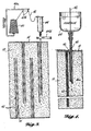
- a source roll or spool 40 of multistrand pliant cord 42 preferably of a compatible material such as a polyester, like Dacron, is arranged to permit feeding or drawing the cord from the source roll through a reservoir 44 of liquid adhesive binder.
- the cord of the order of 1/8" to 3/32" in diameter in a typical application may comprise a weave, braid or twist of threads which will bond to the foam strands and nodes through a properly selected adhesive.
- the adhesive which may, for instance, comprise liquid polyurethane, should also be selected to wet both the cord and the foam matrix and to exhibit flexibility when set so as to minimize undue stress concentrations in the bonds and in the strands and nodes bonded to the cord when the filter body is being compressed and stretched (Figure 5).
- Reservoir 44 in this instance is in the form of an elongated container cup or tube mounting a hollow pointed discharge "needle" 46 at its lower end in registry with a bottom outlet, much like a syringe.
- the needle bore 46a is slightly larger in diameter than the cord so as to pass the cord slidably through the needle after descending through the liquid adhesive in the cup. This coats the cord's surface fibers and/or saturates interstices thereof with the liquid adhesive and it also serves as a lubricant permitting the cord to slide very freely through the needle bore and through the filter body matrix.
- the needle with the cup 44 held upright and with a length of cord projecting beyond the tip of the needle, is advanced through a selected mesh opening in the screen 14 and into the filter body 10 parallel to its longitudinal axis, i.e., in the direction of intended liquid flow. Its leading extremity doubled back over the tip of the needle is driven into the filter body to whatever depth is determined necessary for bonding purposes.
- the cord penetration depth needed is that which enables the doubled cord to contact and become bonded at a sufficient number of contact points with strands and nodes of the filter matrix to bear the load forces of flow (and stretching action) at all depths therein.
- a handle 44b on the reservoir/needle unit may be provided to help hold and manipulate the reservoir and needle in the process of inserting and retracting the needle.
- the spool of cord is shown mounted on a spiral support 40a provided with cord guides 40b.
- the resilient grip on the cord by the surrounding filter body strands hold the looped length of cord in its inserted position to be permanently bonded in that position when the adhesive sets.
- the needle is moved laterally into a new location and reinserted through the screen and into the filter body ( Figure 4) with the cord itself stretched over the intervening screen mesh so as to lash it to the face of the filter body.
- the insertion is repeated at a number of locations suitably distributed over the screen and thereby over the flow cross-sectional area of the filter body.
- the spacings between inserted lengths of cord are not so close as to materially reduce the flow-through open cross section of the filter body, but close enough to permit the bridging spans of matrix material between cords to bear the flow loads without undue sag, as previously stated.
- the myriad of bonds between each inserted cord length and the filter body strand/node elements enable the filter body to withstand high flow velocity pressures without collapse or precompression while permitting numerous purgings of oil by compression of the filter body followed by stretching the same back to its original length and open-pore condition.
Landscapes
- Physics & Mathematics (AREA)
- Thermal Sciences (AREA)
- Chemical & Material Sciences (AREA)
- Chemical Kinetics & Catalysis (AREA)
- Filtering Materials (AREA)
- Filtration Of Liquid (AREA)
- Biological Treatment Of Waste Water (AREA)
- Indicating And Signalling Devices For Elevators (AREA)
- Piezo-Electric Or Mechanical Vibrators, Or Delay Or Filter Circuits (AREA)
- Filtering Of Dispersed Particles In Gases (AREA)
Applications Claiming Priority (2)
| Application Number | Priority Date | Filing Date | Title |
|---|---|---|---|
| US305994 | 1981-09-28 | ||
| US06/305,994 US4356090A (en) | 1981-09-28 | 1981-09-28 | Flow-through oil/water separation filter |
Publications (3)
| Publication Number | Publication Date |
|---|---|
| EP0076023A2 true EP0076023A2 (de) | 1983-04-06 |
| EP0076023A3 EP0076023A3 (en) | 1984-05-16 |
| EP0076023B1 EP0076023B1 (de) | 1986-10-15 |
Family
ID=23183270
Family Applications (1)
| Application Number | Title | Priority Date | Filing Date |
|---|---|---|---|
| EP82303853A Expired EP0076023B1 (de) | 1981-09-28 | 1982-07-21 | Durchströmungsfiltermittel mit vernetztem Schaumstoffkörper, Verfahren und Vorrichtung zur Befestigung eines derartigen Körpers an einem Stützmittel |
Country Status (7)
| Country | Link |
|---|---|
| US (1) | US4356090A (de) |
| EP (1) | EP0076023B1 (de) |
| JP (1) | JPS5864106A (de) |
| CA (1) | CA1193977A (de) |
| DE (1) | DE3273735D1 (de) |
| ES (1) | ES515887A0 (de) |
| NO (1) | NO823199L (de) |
Cited By (1)
| Publication number | Priority date | Publication date | Assignee | Title |
|---|---|---|---|---|
| DE3614238A1 (de) * | 1986-04-26 | 1988-11-24 | Passavant Werke | Verfahren zur reinigung von mit leichtstoffen, insbesondere verseifbaren oelen oder fetten, verunreinigten abwaessern |
Families Citing this family (15)
| Publication number | Priority date | Publication date | Assignee | Title |
|---|---|---|---|---|
| SE8301243L (sv) * | 1983-03-08 | 1984-09-09 | Swed Sorb Corp Ab | Filter for bortseparering av tungflytande vetska |
| US4497707A (en) * | 1983-03-21 | 1985-02-05 | Marine Construction & Design Co. | Regenerable flow-through oil/water separation apparatus |
| US5236585A (en) * | 1992-03-04 | 1993-08-17 | Fink Ronald G | Oil accumulator |
| US5888399A (en) * | 1997-07-21 | 1999-03-30 | Rutledge; Dwight Dean | Water-removing funnel insert and method of application thereof |
| GB0022013D0 (en) * | 2000-09-07 | 2000-10-25 | Earth Canada Corp | Polyurethane oil de-emulsification unit |
| GB0123761D0 (en) * | 2001-10-03 | 2001-11-21 | Pet Mate Ltd | Self-cleaning filter assembly |
| US7662278B2 (en) * | 2001-10-03 | 2010-02-16 | Pet Mate Ltd. | Self-cleaning filter assembly |
| US20050051503A1 (en) * | 2003-09-06 | 2005-03-10 | Holland Robert W. | Coalescer media flexible container and method of use |
| DE202006017102U1 (de) * | 2006-11-07 | 2008-03-20 | Mann+Hummel Gmbh | Filtereinrichtung, insbesondere zur Filtration von Gasen oder Flüssigkeiten in Fahrzeugen |
| US7967980B2 (en) * | 2006-11-17 | 2011-06-28 | Kobelco Construction Machinery Co., Ltd. | Construction machine having working oil tank with filter case |
| US20100326922A1 (en) * | 2009-06-26 | 2010-12-30 | General Electric Company | Oil water separation apparatus |
| US9115580B2 (en) * | 2010-08-20 | 2015-08-25 | Baker Hughes Incorporated | Cellular pump |
| US9114337B2 (en) * | 2011-07-20 | 2015-08-25 | General Electric Company | Device and implementation for filtering oil from water in an appliance |
| KR20210151989A (ko) * | 2013-05-06 | 2021-12-14 | 이너지오 | 제2 액체로부터 액체 탄화수소를 분리하기 위한 장치 및 방법 |
| US12140139B2 (en) * | 2020-09-30 | 2024-11-12 | Solidification Products International, Inc. | Gravity flow filtration of hydrocarbons from an oil-in-water emulsion |
Family Cites Families (9)
| Publication number | Priority date | Publication date | Assignee | Title |
|---|---|---|---|---|
| US2395301A (en) * | 1940-08-03 | 1946-02-19 | Jesse B Hawley | Method of making filter members |
| US3257981A (en) * | 1963-04-30 | 1966-06-28 | Callaway Mills Co | Tufting machine method and apparatus |
| GB1084282A (de) * | 1964-04-29 | 1900-01-01 | ||
| US3645398A (en) * | 1969-07-24 | 1972-02-29 | Exxon Research Engineering Co | Coalescer cartridge and coalescer for oily water |
| US3647606A (en) * | 1969-11-21 | 1972-03-07 | Union Carbide Corp | Semirigid multilayer thermal insulation and method of making same |
| FR2355936A1 (fr) * | 1976-02-03 | 1978-01-20 | Commissariat Energie Atomique | Procede de fabrication de pieces en tissus tri-dimensionnels |
| JPS5389260A (en) * | 1977-01-14 | 1978-08-05 | Nakao Fuirutaa Kougiyou Kk | Method of filtering sludge contained drainages and filter cloth |
| US4213863A (en) * | 1979-01-08 | 1980-07-22 | Marine Construction & Design Co. | Flow-through coalescing separator |
| US4196251A (en) * | 1979-04-16 | 1980-04-01 | International Harvester Company | Rigidized resinous foam core sandwich structure |
-
1981
- 1981-09-28 US US06/305,994 patent/US4356090A/en not_active Expired - Fee Related
-
1982
- 1982-07-21 DE DE8282303853T patent/DE3273735D1/de not_active Expired
- 1982-07-21 EP EP82303853A patent/EP0076023B1/de not_active Expired
- 1982-07-26 CA CA000408073A patent/CA1193977A/en not_active Expired
- 1982-09-17 JP JP57161095A patent/JPS5864106A/ja active Pending
- 1982-09-22 NO NO823199A patent/NO823199L/no unknown
- 1982-09-22 ES ES515887A patent/ES515887A0/es active Granted
Cited By (1)
| Publication number | Priority date | Publication date | Assignee | Title |
|---|---|---|---|---|
| DE3614238A1 (de) * | 1986-04-26 | 1988-11-24 | Passavant Werke | Verfahren zur reinigung von mit leichtstoffen, insbesondere verseifbaren oelen oder fetten, verunreinigten abwaessern |
Also Published As
| Publication number | Publication date |
|---|---|
| ES8402511A1 (es) | 1984-03-01 |
| CA1193977A (en) | 1985-09-24 |
| EP0076023B1 (de) | 1986-10-15 |
| US4356090A (en) | 1982-10-26 |
| NO823199L (no) | 1983-03-29 |
| EP0076023A3 (en) | 1984-05-16 |
| JPS5864106A (ja) | 1983-04-16 |
| ES515887A0 (es) | 1984-03-01 |
| DE3273735D1 (en) | 1986-11-20 |
Similar Documents
| Publication | Publication Date | Title |
|---|---|---|
| US4356090A (en) | Flow-through oil/water separation filter | |
| CA1136058A (en) | Flow-through coalescing separator | |
| DE69230766T2 (de) | Konzentration von feststoffen in einer aufschlammung unter anwendung von kohlfasermembranen | |
| DE60300826T2 (de) | Fluidfilter | |
| DE3231425C2 (de) | ||
| US5643458A (en) | Sludge dehydrating press and method for treating sludge | |
| CA1188626A (en) | Filtration thickening method and apparatus | |
| US2819800A (en) | Filtering apparatus and filter unit therefor | |
| US4022694A (en) | Oil-water separation apparatus | |
| WO2000061952A1 (de) | Betätigungseinrichtung | |
| EA000332B1 (ru) | Деформируемый скважинный сетчатый фильтр и способ его установки | |
| DE3320091A1 (de) | Schlauchpumpe | |
| DE2324575B2 (de) | Anordnung zur Ausfilterung strömungsgetragener Aerosole sowie Verfahren zur Herstellung der Anordnung | |
| US4076467A (en) | Specially reinforced flexible tube pumping chamber | |
| GB2059290A (en) | Methods for assembling permeators | |
| US3762560A (en) | Tube pressure filters | |
| EP0455117B1 (de) | Schlammentwässerungspresse | |
| DE2721124A1 (de) | Vorrichtung zur trennung von mischungen ineinander unloeslicher fluessigkeiten | |
| DE3041452C2 (de) | Schlauch | |
| DE1525508B2 (de) | Rollmembran | |
| JPS59179117A (ja) | 再生型濾過装置及びフイルタ・カ−トリツジ | |
| US4058464A (en) | Helically wound expandable filter | |
| DE3782822T2 (de) | Filtrieranordnung und verfahren. | |
| DE2519959C2 (de) | Vorrichtung zur Öl-Wasser-Trennung | |
| EP1778379A1 (de) | Vorrichtung und verfahren zum filtrieren eines fluids, insbesondere für kunststoffverarbeitende anlagen |
Legal Events
| Date | Code | Title | Description |
|---|---|---|---|
| PUAI | Public reference made under article 153(3) epc to a published international application that has entered the european phase |
Free format text: ORIGINAL CODE: 0009012 |
|
| AK | Designated contracting states |
Designated state(s): DE FR GB IT NL |
|
| PUAL | Search report despatched |
Free format text: ORIGINAL CODE: 0009013 |
|
| AK | Designated contracting states |
Designated state(s): DE FR GB IT NL |
|
| 17P | Request for examination filed |
Effective date: 19841012 |
|
| GRAA | (expected) grant |
Free format text: ORIGINAL CODE: 0009210 |
|
| AK | Designated contracting states |
Kind code of ref document: B1 Designated state(s): DE FR GB IT NL |
|
| ITF | It: translation for a ep patent filed | ||
| REF | Corresponds to: |
Ref document number: 3273735 Country of ref document: DE Date of ref document: 19861120 |
|
| ET | Fr: translation filed | ||
| PLBE | No opposition filed within time limit |
Free format text: ORIGINAL CODE: 0009261 |
|
| STAA | Information on the status of an ep patent application or granted ep patent |
Free format text: STATUS: NO OPPOSITION FILED WITHIN TIME LIMIT |
|
| 26N | No opposition filed | ||
| PG25 | Lapsed in a contracting state [announced via postgrant information from national office to epo] |
Ref country code: NL Effective date: 19880201 |
|
| NLV4 | Nl: lapsed or anulled due to non-payment of the annual fee | ||
| PG25 | Lapsed in a contracting state [announced via postgrant information from national office to epo] |
Ref country code: GB Effective date: 19880721 |
|
| GBPC | Gb: european patent ceased through non-payment of renewal fee | ||
| PG25 | Lapsed in a contracting state [announced via postgrant information from national office to epo] |
Ref country code: FR Free format text: LAPSE BECAUSE OF NON-PAYMENT OF DUE FEES Effective date: 19890331 |
|
| PG25 | Lapsed in a contracting state [announced via postgrant information from national office to epo] |
Ref country code: DE Effective date: 19890401 |
|
| REG | Reference to a national code |
Ref country code: FR Ref legal event code: ST |