EP0076039A1 - Drehzahlsteuerung für Elektrokraftwerkzeuge mit einem Gleichstrommotor - Google Patents
Drehzahlsteuerung für Elektrokraftwerkzeuge mit einem Gleichstrommotor Download PDFInfo
- Publication number
- EP0076039A1 EP0076039A1 EP82304554A EP82304554A EP0076039A1 EP 0076039 A1 EP0076039 A1 EP 0076039A1 EP 82304554 A EP82304554 A EP 82304554A EP 82304554 A EP82304554 A EP 82304554A EP 0076039 A1 EP0076039 A1 EP 0076039A1
- Authority
- EP
- European Patent Office
- Prior art keywords
- motor
- transistor
- astable multivibrator
- duty cycle
- controlling
- Prior art date
- Legal status (The legal status is an assumption and is not a legal conclusion. Google has not performed a legal analysis and makes no representation as to the accuracy of the status listed.)
- Withdrawn
Links
- 230000007246 mechanism Effects 0.000 abstract description 10
- 230000001052 transient effect Effects 0.000 abstract description 4
- 239000003990 capacitor Substances 0.000 description 5
- 230000001939 inductive effect Effects 0.000 description 4
- 230000007704 transition Effects 0.000 description 3
- 230000008859 change Effects 0.000 description 2
- 230000004044 response Effects 0.000 description 2
- 230000003321 amplification Effects 0.000 description 1
- OJIJEKBXJYRIBZ-UHFFFAOYSA-N cadmium nickel Chemical compound [Ni].[Cd] OJIJEKBXJYRIBZ-UHFFFAOYSA-N 0.000 description 1
- 230000006866 deterioration Effects 0.000 description 1
- 238000010586 diagram Methods 0.000 description 1
- 238000007599 discharging Methods 0.000 description 1
- 230000005669 field effect Effects 0.000 description 1
- 238000010304 firing Methods 0.000 description 1
- 238000004519 manufacturing process Methods 0.000 description 1
- 238000003199 nucleic acid amplification method Methods 0.000 description 1
Images

Classifications
-
- H—ELECTRICITY
- H02—GENERATION; CONVERSION OR DISTRIBUTION OF ELECTRIC POWER
- H02P—CONTROL OR REGULATION OF ELECTRIC MOTORS, ELECTRIC GENERATORS OR DYNAMO-ELECTRIC CONVERTERS; CONTROLLING TRANSFORMERS, REACTORS OR CHOKE COILS
- H02P7/00—Arrangements for regulating or controlling the speed or torque of electric DC motors
- H02P7/06—Arrangements for regulating or controlling the speed or torque of electric DC motors for regulating or controlling an individual DC dynamo-electric motor by varying field or armature current
- H02P7/18—Arrangements for regulating or controlling the speed or torque of electric DC motors for regulating or controlling an individual DC dynamo-electric motor by varying field or armature current by master control with auxiliary power
- H02P7/24—Arrangements for regulating or controlling the speed or torque of electric DC motors for regulating or controlling an individual DC dynamo-electric motor by varying field or armature current by master control with auxiliary power using discharge tubes or semiconductor devices
- H02P7/28—Arrangements for regulating or controlling the speed or torque of electric DC motors for regulating or controlling an individual DC dynamo-electric motor by varying field or armature current by master control with auxiliary power using discharge tubes or semiconductor devices using semiconductor devices
- H02P7/285—Arrangements for regulating or controlling the speed or torque of electric DC motors for regulating or controlling an individual DC dynamo-electric motor by varying field or armature current by master control with auxiliary power using discharge tubes or semiconductor devices using semiconductor devices controlling armature supply only
- H02P7/29—Arrangements for regulating or controlling the speed or torque of electric DC motors for regulating or controlling an individual DC dynamo-electric motor by varying field or armature current by master control with auxiliary power using discharge tubes or semiconductor devices using semiconductor devices controlling armature supply only using pulse modulation
Definitions
- This invention relates to a manually operable speed control for power tools with a DC motor.
- This invention is particularly, although not exclusively, suited for use with a hand held battery powered tool such as a drill.
- a hand held battery powered tool such as a drill.
- Such tools typically utilize a rechargeable battery pack which supplies a relatively low DC voltage, such as 7.2 volts, and may be required to supply a maximum current of approximately 40 amperes.
- the low voltage and high currents which must be handled, switching transients, power dissipation, and the very limited space available in compact hand held tools illustrate some of the severe operating restrictions encountered when attempting to provide DC speed controls for such tools.
- United States Patent No. 3,209,228 discloses an AC motor speed control wherein a manually operated trigger controls the wiper arm of a potentiometer to vary an RC circuit which determines the firing point of an SCR in series with the motor.
- Electromechanical vibrators having a variable rate of vibration and a pair of contacts, which open and close with the vibrations, can be used to control DC motors. These contacts are connected in series with the DC motor to change the average current flowing thereby varying the speed of the motor. How- . ever, these devices have disadvantages such as contact bounce, arcing between the contacts, and a limited life because of mechanical wear.
- Another object of the present invention is to. control the average current flowing through the DC motor by controlling the duty cycle of an astable multivibrator which in turn controls a switching element in series with the motor.
- a more specific object of the present invention is to control the ON to OFF switching time of the series switching element to minimize potentially harmful voltage transients.
- a further object of the present invention is to utilize a high'gain series switching device, such as a field effect transistor, which can be driven directly from an integrated circuit astable.
- This invention is suitable for use in a power tool having a DC motor and a manually operated mechanism for controlling the speed of the motor.
- An astable multivibrator having a variable duty cycle is coupled to a transistor, preferably an FET, connected in series with the motor to function as a series switching deviee.
- a means coupled to said control . mechanism is used to control the duty cycle of the astable multivibrator which in turn controls the duty cycle of the series switching transistor thereby controlling the average current and hence speed of the motor.
- a first circuit means connected between the transistor and astable multivibrator is used to control the turn off time of the transistor to minimize transient voltage spikes.
- a diode connected in parallel with the motor is used to dissipate a substantial part of the inductive.energy stored in the motor when the motor is turned off.
- the drill 10 includes a DC motor 12, a manually operable trigger mechanism 14 for controlling the speed of the motor, and a battery 16 which supplies power to the drill.
- the battery can be quickly removed from handle 18 for recharging.
- the circuitry of the present invention is mounted on a printed circuit board which may be contained within a switch housing 20 that includes the trigger control mechanism.
- a series switching device 22, to be described below, is mounted separately to a heat sink 24 for efficient heat transfer of the power dissipated by the switching device.
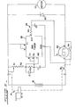
- An integrated circuit 26 functions as an astable multivibrator whose frequency and duty cycle are controlled by the components associated with pins 2, 6, 7.
- the output of the astable multivibrator at pin 3 is coupled through delay circuit 28 to the gate of an FET 22 which has its drain and source connected in series with motor 12 and thus functions as the series switching device.
- Diode 30 is connected in parallel with the motor to aid in dissipating the energy stored in the motor during ON to OFF switching transitions.
- Battery 16 is connected in series with the motor, the FET, and series switch 32 which is controlled by the trigger mechanism 14 as indicated by the dashed line.
- Switch 32 serves as a conventional ON/OFF switch which is open when the trigger is fully extended and which is-closed when the trigger is retracted.
- a bypass switch 34 connected -in parallel with the FET, is also controlled by the trigger mechanism such that it is normally open and is closed only near maximum retraction of the trigger to place a short circuit across the FET thereby applying the full power of the battery to the motor.
- the position of the trigger mechanism also controls the wiper arm of potentiometer R1 such that increasing retraction of the trigger produces increasing motor speed until bypass switch 34 is closed.
- Trigger control mechanisms capable of -providing these functions are known in the art.
- the duty cycle and frequency of the astable multivibrator varies in response to resistance changes of R1 causing a corresponding change in the ratio of ON to OFF times of the FET. This controls the average DC current flowing through motor 12 which in turn controls the speed of the motor.
- the delay circuit 28 is used to provide a more gradual ON to OFF transition switching time of the FET to reduce undesirable transient responses and to provide more time for diode 30 to
- the integrated circuit 26 is preferably a 555 timer connected to function as an astable multivibrator, that is, the switching threshold (pin 6) is connected to the trigger input (pin 2) and the discharge output (pin 7) is connected to the associated components as shown.
- the switching threshold (pin 6) is connected to the trigger input (pin 2) and the discharge output (pin 7) is connected to the associated components as shown.
- the astable multivibrator output (pin 3) is in its high state of approximately the battery voltage V, the FET is ON or fully conducting; when the output is in its low state or approximately zero volts, the FET is OFF or nonconducting.
- the astable multivibrator's output is high during the time capacitor C1 is charging from one-third to two-thirds of battery voltage V and is low during the time capacitor C1 is discharging from two-thirds to one-third of V.
- the delay circuit 28 which consists of resistor R4 and capacitor C2, increases the switching transition times of the ) FET. It is desirable to decrease the extremely rapid switching times of the output of the astable multivibrator in order to minimize the switching transients which would otherwise be present because of the generally inductive nature of motor 12. If the FET were switched from ON to OFF extremely rapidly, the inductance of the motor would generate a large voltage spike or transient which could destroy or cause deterioration of the FET.
- Tne FET must of course be selected to have sufficient power dissipation and DC current capabilities to handle tne cnaracteristics of the particular motor utilized.
- battery 16 consisted of six nickel-cadmium cells in series having a no load voltage of 7.2 volts (but not limited to a no load voltage of 7.2 volts) the current of a typical DC drill motor could range from 2 amps at no load, 8 amps' at normal load, and 40 amps in a motor stalled condition.
- the FET must be capable of handling substantial current.
- the FET may consist of a model BUZ-10 available commercially from Siemens Company. The high gain of the FET as compared with a bipolar transistor allows the 555 integrated circuit to drive it without additional amplification.
- an astable multivibrator frequency in the 1.0-1.5 KHZ range and an ON duty cycle between 0-40% was found to produce adequate motor control and to maintain the FET within safe current and power dissipation operating regions.
- the time constant of the RC network of the delay circuit 28, that is R4 C2 may be approximately 25 microseconds in such an application.
- Figure 3 illustates an exemplary waveform of the voltage 40 across the motor and the current 42 flowing through the motor.
- the time periods T1 and T2 correspond to the ON and OFF time periods of the FET.
- the time period T of the waveform equals the sum of T1 and T2.
- the present invention provides a DC motor speed control which requires few components and can be housed in a very small space inside a power tool. Since this speed control has only a limited number of parts, it is very reliable and easy to manufacture.
Landscapes
- Engineering & Computer Science (AREA)
- Power Engineering (AREA)
- Control Of Direct Current Motors (AREA)
Applications Claiming Priority (2)
| Application Number | Priority Date | Filing Date | Title |
|---|---|---|---|
| US29815381A | 1981-08-31 | 1981-08-31 | |
| US298153 | 1981-08-31 |
Publications (1)
| Publication Number | Publication Date |
|---|---|
| EP0076039A1 true EP0076039A1 (de) | 1983-04-06 |
Family
ID=23149286
Family Applications (1)
| Application Number | Title | Priority Date | Filing Date |
|---|---|---|---|
| EP82304554A Withdrawn EP0076039A1 (de) | 1981-08-31 | 1982-08-27 | Drehzahlsteuerung für Elektrokraftwerkzeuge mit einem Gleichstrommotor |
Country Status (2)
| Country | Link |
|---|---|
| EP (1) | EP0076039A1 (de) |
| JP (1) | JPS5851797A (de) |
Cited By (11)
| Publication number | Priority date | Publication date | Assignee | Title |
|---|---|---|---|---|
| EP0215325A3 (en) * | 1985-09-10 | 1988-01-07 | Curtis Instruments, Inc. | Solid state d.c. motor control |
| EP0376214A1 (de) * | 1988-12-23 | 1990-07-04 | OMRON Corporation | Motorregelungsschaltung |
| EP0395401A3 (en) * | 1989-04-26 | 1990-12-27 | Makita Electric Works Ltd | Switching circuit for varying the rotational speed of a motor |
| EP0680808A1 (de) * | 1994-04-25 | 1995-11-08 | Black & Decker Inc. | Schlagwerkzeug mit Geschwindigkeitsregelschaltung |
| GB2314980A (en) * | 1996-07-02 | 1998-01-14 | Defond Mfg Ltd | Power tool speed controller |
| NL1003612C2 (nl) * | 1996-07-16 | 1998-01-21 | Capax B V | Regelbare weerstand met een van flexibel materiaal vervaardigde loper. |
| US6359545B1 (en) | 1998-01-09 | 2002-03-19 | Capax B.V. | Adjustable resistor with slider made from elastomeric material |
| EP1073191A3 (de) * | 1999-07-26 | 2003-06-18 | Makita Corporation | Drehzahlregelkreis für einen Gleichstrommotor |
| GB2414875A (en) * | 2004-06-02 | 2005-12-07 | Bosch Gmbh Robert | A pulse-width-modulated multivibrator for a hand tool motor controller |
| US9912020B2 (en) | 2013-03-12 | 2018-03-06 | Milwaukee Electric Tool Corporation | Battery pack with heat sink |
| US10720860B2 (en) | 2018-01-03 | 2020-07-21 | Milwaukee Electric Tool Corporation | Electronic braking in a power tool |
Families Citing this family (3)
| Publication number | Priority date | Publication date | Assignee | Title |
|---|---|---|---|---|
| JPS60148397A (ja) * | 1984-01-10 | 1985-08-05 | Suzuki Mekatoronikusu Kk | 転流ダイオ−ドを省いたモ−タドライブ回路 |
| US4673851A (en) * | 1986-03-31 | 1987-06-16 | General Motors Corporation | PWM motor operating system with RFI suppression |
| KR101868032B1 (ko) * | 2015-10-01 | 2018-06-22 | 이용일 | 비안정 멀티바이브레이터를 이용한 가변속도 가능한 저전력 모터제어 |
Citations (2)
| Publication number | Priority date | Publication date | Assignee | Title |
|---|---|---|---|---|
| GB1413476A (en) * | 1971-11-10 | 1975-11-12 | Cav Ltd | Speed control for dc motors |
| GB1562252A (en) * | 1978-02-01 | 1980-03-05 | Lucas Industries Ltd | Motor control units |
-
1982
- 1982-08-27 EP EP82304554A patent/EP0076039A1/de not_active Withdrawn
- 1982-08-31 JP JP15164882A patent/JPS5851797A/ja active Pending
Patent Citations (2)
| Publication number | Priority date | Publication date | Assignee | Title |
|---|---|---|---|---|
| GB1413476A (en) * | 1971-11-10 | 1975-11-12 | Cav Ltd | Speed control for dc motors |
| GB1562252A (en) * | 1978-02-01 | 1980-03-05 | Lucas Industries Ltd | Motor control units |
Non-Patent Citations (3)
| Title |
|---|
| ELECTRONIC DESIGN, Vol. 29, No. 7, 31 March 1981, Denville. H.L. MORGAN "555 timer provides PWM drive for low-cost dc motor control" pages 193, 194, 196 * |
| TOUTE L'ELECTRONIQUE, No. 460, January 1981, Paris. C. VERBEEK "Les MOS de puissance pour la commande des moteurs" pages 47 to 50 * |
| WIRELESS WORLD, Vol. 85, No. 1520, April 1979, London. J.D. STUMBLES "Motor speed controller" pages 83 to 86 * |
Cited By (18)
| Publication number | Priority date | Publication date | Assignee | Title |
|---|---|---|---|---|
| EP0215325A3 (en) * | 1985-09-10 | 1988-01-07 | Curtis Instruments, Inc. | Solid state d.c. motor control |
| EP0376214A1 (de) * | 1988-12-23 | 1990-07-04 | OMRON Corporation | Motorregelungsschaltung |
| EP0395401A3 (en) * | 1989-04-26 | 1990-12-27 | Makita Electric Works Ltd | Switching circuit for varying the rotational speed of a motor |
| EP0680808A1 (de) * | 1994-04-25 | 1995-11-08 | Black & Decker Inc. | Schlagwerkzeug mit Geschwindigkeitsregelschaltung |
| US5526460A (en) * | 1994-04-25 | 1996-06-11 | Black & Decker Inc. | Impact wrench having speed control circuit |
| AU684147B2 (en) * | 1994-04-25 | 1997-12-04 | Black & Decker Incorporated | Impact tool having speed control circuit |
| GB2314980A (en) * | 1996-07-02 | 1998-01-14 | Defond Mfg Ltd | Power tool speed controller |
| GB2314980B (en) * | 1996-07-02 | 2000-06-28 | Defond Mfg Ltd | Power tool speed controller |
| WO1999035654A1 (en) * | 1996-07-16 | 1999-07-15 | Capax B.V. | Adjustable resistor with slider made from elastomeric material |
| NL1003612C2 (nl) * | 1996-07-16 | 1998-01-21 | Capax B V | Regelbare weerstand met een van flexibel materiaal vervaardigde loper. |
| US6359545B1 (en) | 1998-01-09 | 2002-03-19 | Capax B.V. | Adjustable resistor with slider made from elastomeric material |
| EP1073191A3 (de) * | 1999-07-26 | 2003-06-18 | Makita Corporation | Drehzahlregelkreis für einen Gleichstrommotor |
| GB2414875A (en) * | 2004-06-02 | 2005-12-07 | Bosch Gmbh Robert | A pulse-width-modulated multivibrator for a hand tool motor controller |
| US9912020B2 (en) | 2013-03-12 | 2018-03-06 | Milwaukee Electric Tool Corporation | Battery pack with heat sink |
| US10720860B2 (en) | 2018-01-03 | 2020-07-21 | Milwaukee Electric Tool Corporation | Electronic braking in a power tool |
| US11075594B2 (en) | 2018-01-03 | 2021-07-27 | Milwaukee Electric Tool Corporation | Electronic braking in a power tool |
| US11695352B2 (en) | 2018-01-03 | 2023-07-04 | Milwaukee Electric Tool Corporation | Electronic braking in a power tool |
| US12166447B2 (en) | 2018-01-03 | 2024-12-10 | Milwaukee Electric Tool Corporation | Electronic braking in a power tool |
Also Published As
| Publication number | Publication date |
|---|---|
| JPS5851797A (ja) | 1983-03-26 |
Similar Documents
| Publication | Publication Date | Title |
|---|---|---|
| EP0076039A1 (de) | Drehzahlsteuerung für Elektrokraftwerkzeuge mit einem Gleichstrommotor | |
| US4161023A (en) | Up-and-down chopper circuit | |
| JP4124041B2 (ja) | 充電機能付き直流電源装置 | |
| US4706177A (en) | DC-AC inverter with overload driving capability | |
| US6696814B2 (en) | Microprocessor for controlling the speed and frequency of a motor shaft in a power tool | |
| EP1079495A2 (de) | Batterieladegerät mit niedrigem Wärmeverlust | |
| US4841165A (en) | D. C. power controller | |
| EP0102689A2 (de) | Konstantes Spannungszeit-Regelgerät | |
| JP3978312B2 (ja) | サイリスタ用ゲートドライバ | |
| US5528721A (en) | Direct current motor speed control apparatus | |
| US4638226A (en) | Speed control system with feedback and soft-start | |
| US4814966A (en) | Shunt switched resistor regulator with diode snubber | |
| EP0299088B1 (de) | Ansteuerschaltung | |
| WO1993007675A1 (en) | Direct current power control circuit for use in conjunction with regulated input signal | |
| US20070126407A1 (en) | Electrical appliance with battery protection | |
| US7230354B2 (en) | Driver system for MOSFET based, high voltage, electronic relays for AC power switching and inductive loads | |
| CA2073397C (en) | Power supply switching circuit for a compact portable telephone set | |
| US4816741A (en) | Switched resistor regulator with diode-snubber for parasitic inductance in switched resistor | |
| JPH077807A (ja) | 電動車制御装置 | |
| US4894588A (en) | High efficiency flasher | |
| US6483268B1 (en) | DC motor brake | |
| US5003628A (en) | Variable speed D.C. motor control | |
| JP2003133926A (ja) | 突入電流抑止回路 | |
| ES2081232A2 (es) | Dispositivo intermitente electronico estatico para el mando de los indicadores de direccion de un vehiculo automovil. | |
| JPS637889B2 (de) |
Legal Events
| Date | Code | Title | Description |
|---|---|---|---|
| PUAI | Public reference made under article 153(3) epc to a published international application that has entered the european phase |
Free format text: ORIGINAL CODE: 0009012 |
|
| AK | Designated contracting states |
Designated state(s): DE FR GB IT NL |
|
| STAA | Information on the status of an ep patent application or granted ep patent |
Free format text: STATUS: THE APPLICATION IS DEEMED TO BE WITHDRAWN |
|
| 18D | Application deemed to be withdrawn |
Effective date: 19840315 |
|
| RIN1 | Information on inventor provided before grant (corrected) |
Inventor name: GAWRON, ALEX F. Inventor name: NEUMANN, PETER N. |