EP0076041A1 - Fahrzeugsitzverstellvorrichtung - Google Patents
Fahrzeugsitzverstellvorrichtung Download PDFInfo
- Publication number
- EP0076041A1 EP0076041A1 EP82304575A EP82304575A EP0076041A1 EP 0076041 A1 EP0076041 A1 EP 0076041A1 EP 82304575 A EP82304575 A EP 82304575A EP 82304575 A EP82304575 A EP 82304575A EP 0076041 A1 EP0076041 A1 EP 0076041A1
- Authority
- EP
- European Patent Office
- Prior art keywords
- slide
- pair
- ears
- trigger
- slide member
- Prior art date
- Legal status (The legal status is an assumption and is not a legal conclusion. Google has not performed a legal analysis and makes no representation as to the accuracy of the status listed.)
- Granted
Links
- 230000007246 mechanism Effects 0.000 title claims description 5
- 210000005069 ears Anatomy 0.000 claims abstract description 15
- 238000005096 rolling process Methods 0.000 abstract description 2
- 230000006378 damage Effects 0.000 abstract 1
- 230000015572 biosynthetic process Effects 0.000 description 2
- 230000006835 compression Effects 0.000 description 2
- 238000007906 compression Methods 0.000 description 2
- 238000010276 construction Methods 0.000 description 2
- 238000005755 formation reaction Methods 0.000 description 2
- 238000003197 gene knockdown Methods 0.000 description 2
- 238000001746 injection moulding Methods 0.000 description 2
- 238000004519 manufacturing process Methods 0.000 description 2
- 230000002159 abnormal effect Effects 0.000 description 1
- 239000002131 composite material Substances 0.000 description 1
- 230000000994 depressogenic effect Effects 0.000 description 1
- 239000000463 material Substances 0.000 description 1
- 238000000034 method Methods 0.000 description 1
- 238000000926 separation method Methods 0.000 description 1
Images


Classifications
-
- B—PERFORMING OPERATIONS; TRANSPORTING
- B60—VEHICLES IN GENERAL
- B60N—SEATS SPECIALLY ADAPTED FOR VEHICLES; VEHICLE PASSENGER ACCOMMODATION NOT OTHERWISE PROVIDED FOR
- B60N2/00—Seats specially adapted for vehicles; Arrangement or mounting of seats in vehicles
- B60N2/02—Seats specially adapted for vehicles; Arrangement or mounting of seats in vehicles the seat or part thereof being movable, e.g. adjustable
- B60N2/04—Seats specially adapted for vehicles; Arrangement or mounting of seats in vehicles the seat or part thereof being movable, e.g. adjustable the whole seat being movable
- B60N2/06—Seats specially adapted for vehicles; Arrangement or mounting of seats in vehicles the seat or part thereof being movable, e.g. adjustable the whole seat being movable slidable
- B60N2/07—Slide construction
- B60N2/0702—Slide construction characterised by its cross-section
- B60N2/071—T-shaped
-
- B—PERFORMING OPERATIONS; TRANSPORTING
- B60—VEHICLES IN GENERAL
- B60N—SEATS SPECIALLY ADAPTED FOR VEHICLES; VEHICLE PASSENGER ACCOMMODATION NOT OTHERWISE PROVIDED FOR
- B60N2/00—Seats specially adapted for vehicles; Arrangement or mounting of seats in vehicles
- B60N2/02—Seats specially adapted for vehicles; Arrangement or mounting of seats in vehicles the seat or part thereof being movable, e.g. adjustable
- B60N2/04—Seats specially adapted for vehicles; Arrangement or mounting of seats in vehicles the seat or part thereof being movable, e.g. adjustable the whole seat being movable
- B60N2/06—Seats specially adapted for vehicles; Arrangement or mounting of seats in vehicles the seat or part thereof being movable, e.g. adjustable the whole seat being movable slidable
- B60N2/07—Slide construction
- B60N2/0702—Slide construction characterised by its cross-section
- B60N2/0715—C or U-shaped
-
- B—PERFORMING OPERATIONS; TRANSPORTING
- B60—VEHICLES IN GENERAL
- B60N—SEATS SPECIALLY ADAPTED FOR VEHICLES; VEHICLE PASSENGER ACCOMMODATION NOT OTHERWISE PROVIDED FOR
- B60N2/00—Seats specially adapted for vehicles; Arrangement or mounting of seats in vehicles
- B60N2/02—Seats specially adapted for vehicles; Arrangement or mounting of seats in vehicles the seat or part thereof being movable, e.g. adjustable
- B60N2/04—Seats specially adapted for vehicles; Arrangement or mounting of seats in vehicles the seat or part thereof being movable, e.g. adjustable the whole seat being movable
- B60N2/06—Seats specially adapted for vehicles; Arrangement or mounting of seats in vehicles the seat or part thereof being movable, e.g. adjustable the whole seat being movable slidable
- B60N2/08—Seats specially adapted for vehicles; Arrangement or mounting of seats in vehicles the seat or part thereof being movable, e.g. adjustable the whole seat being movable slidable characterised by the locking device
- B60N2/0812—Location of the latch
- B60N2/0825—Location of the latch outside the rail
-
- B—PERFORMING OPERATIONS; TRANSPORTING
- B60—VEHICLES IN GENERAL
- B60N—SEATS SPECIALLY ADAPTED FOR VEHICLES; VEHICLE PASSENGER ACCOMMODATION NOT OTHERWISE PROVIDED FOR
- B60N2/00—Seats specially adapted for vehicles; Arrangement or mounting of seats in vehicles
- B60N2/02—Seats specially adapted for vehicles; Arrangement or mounting of seats in vehicles the seat or part thereof being movable, e.g. adjustable
- B60N2/04—Seats specially adapted for vehicles; Arrangement or mounting of seats in vehicles the seat or part thereof being movable, e.g. adjustable the whole seat being movable
- B60N2/06—Seats specially adapted for vehicles; Arrangement or mounting of seats in vehicles the seat or part thereof being movable, e.g. adjustable the whole seat being movable slidable
- B60N2/08—Seats specially adapted for vehicles; Arrangement or mounting of seats in vehicles the seat or part thereof being movable, e.g. adjustable the whole seat being movable slidable characterised by the locking device
- B60N2/0831—Movement of the latch
- B60N2/0837—Movement of the latch pivoting
- B60N2/085—Movement of the latch pivoting about a transversal axis
Definitions
- This invention relates to vehicle seat slide mechanisms.
- Vehicle seat slide mechanisms such as are provided for the fore-and-aft adjustment of the front seats of a motor car or the driving seat of other types of vehicle, comprise a first slide member arranged to be fixed on the floor of the vehicle of a second slide member attached to the body of the vehicle seat and slidably arranged in the first slide member. It is normal to provide two pairs of slide members, one pair on either side of the seat to make a vehicle seat slide assembly.
- This invention has as an object to provide an improved construction for such a slide member pair.
- the present invention uses the idea that if there are respective parts of the sections of the two slides which are spaced from one another so that there is little resistance to sliding and there is some manufacturing tolerances, nevertheless, the respective parts can be close enough together to come into contact along a substantial part of the lengths of the slides under very high loads to prevent the slides separating and allowing the seat and passengers to be thrown against the body of the vehicle.
- Such a closely spaced part of a slide section can be beyond a part defining a track for a ball or roller bearing.
- the sections have to be deformed slightly to accommodate the balls so that the sections are then pre-stressed and the pair will not rattle.
- rollers or balls carrying vertical loads between the slides may be rollers or balls carrying vertical loads between the slides as well as balls carrying transverse loads.
- Balls can have thrust lines at an angle to the horizontal and vertical so that both transverse and vertical loads between the slides of a pair can be carried by the balls.
- a convenient form of the invention consists of a 'U' section slide and a 'T' section slide within the 'U'.
- the arms of the 'U' and the ends of the bar of the 'T' can define ball tracks and can define respective surfaces which come into contact under excessive loads.
- the present invention provides a vehicle slide pair with notches on one slide and a latch for locking the slides in one of a number of positions of longitudinal adjustment.
- a trigger for releasing the latch comprises a pair of wires or rods arranged to extend transversely to the slides with one wire in a hole in one slide member constituting a pivot, and the other wire in a slot in that slide member constituting a guide, and a release member and a body adapted to be mounted on the wires respectively on opposite sides of the slide pair.
- the two slide pairs and the components of the trigger can be supplied to a manufacturer in knock-down form, so that the package of components is compact, and assembly is quite easy by passing the wires through the hole and slot and mounting the release member and the body on them.
- the wires are swaged into the body or the release member, so that after they have been passed through the hole and the slot, the other only has to be press-fitted onto the exposed ends of the wires to hold the components assembled.
- the body may in fact constitute a cross tube extending transversely between corresponding triggers on the two pairs of slide members one at each side of the seat.
- the release member could be an injection moulding made in accordance with a particular customer's requirements.
- the latch which can be supplied assembled with a pair of slide members will have a part which can be lifted for example against a spring by the wire in the slot as the other wire turns in the pivot hole. Possibly, the latch will be formed with a curved portion to accommodate the wires or one of them.
- the spring will act to cause. the latch to re-engage notches in any position of the slides when the release member is released.
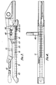
- FIGURE 1 shows a side elevation of a slide member pair arranged to support one side of a vehicle seat from a vehicle floor. A second virtually identical pair would.be used on the opposite side of the seat.
- the slide assembly indicated generally at 10 comprises a first slide member 11. arranged to be fixed on the vertical floor by means of mounting pads or.formations 12 and 13, and a second slide member 14 slidably arranged in the slide member 11 and arranged to be attached to, and support, the body of a vertical seat.
- the slide member 11 over the major portion of its length between the formations 12 and 13 is of generally U-shaped channel cross-section.
- the cross-section includes a flat horizontal base portion 15, having upwardly extending arms 16 and 17, one on either side of the portion 15.
- the flat portion 15 provides an upwardly facing horizontal surface 18 forming a roller track for a series of rollers 19 in side-by-side pairs which are spaced along the track 15 by a cage 20.
- the second slide member 14 is of generally inverted 'T' shaped cross section and.offers a downwardly facing horizontal surface 21 underneath the horizontal bar of the T. This surface forms a second roller track running on the rollers 19, thus supporting the weight of the seat on the first slide member and allowing free sliding movement between the slide members.
- the slide member 14 is preferably formed from two folded and pressed sheet material components secured together to form a vertical bar of the T-cross-section as indicated at 22, thus offering a vertical flange for attachment to the seat body, and for attachment of such items as seat belt anchorages as shown for example as a boss 23.
- the sheet members indicated at 24 and 25 each have a vertical flange portion 26 and then extend outwards with portions 27 to define the horizontal surface 21 and upwards to define ears 28..
- a first ball track is formed at the arcuate portions between each of the portions 27 and ears 28 to receive ball bearings 29.
- the upper ends of the arms'16 and 17 of the first slide member are turned inwards and downwards over. the ears 28 and are curved to terminate in arcuate portions 30 forming second ball tracks for the balls 29.
- the balls 29 provide a rolling bearing between the first and second slide members which resists transverse separation of the first and second.slide members.
- the centres of the arcuate portions 27,28 and 30 lie on axes at 45° to the horizontal and vertical in FIGURE 2 so that the balls 29 can carry some vertical load as well as transverse load between the slides and that enables the portions 30 and 28 to be designed to be sprung apart a little to accommodate the balls 29 during assembly.
- Theportions 27 are also sprung to admit the rollers 19.
- the two slide members are only in contact through the balls and rollers during normal use so that sliding is easy.
- an abnormal load such as may be encountered in an accident when seat belt loads are transmitted to the second slide member can cause the ends of the ears 28 to come into contact with the turned over portions of the arms 16 and 17 along the whole length of the slide to resist local deformation.at the balls.
- the turned over portions of the arms 16 and 17, as indicated at 31, and the ears 28, are formed with a series of correspondingly pitched notches, and a locking trigger, indicated at 32, in FIGURE 2, is arranged to engage any such notches which are brought into chosen alignment to lock the slide against fore and aft movement, in known manner per se.
- the portions 26 of the components 24 and 25 of the second slide member may be spaced apart at their lower edges as indicated at 33, to provide internal space for the operating mechanism for the trigger 32.
- FIGURES 3,4 and 5 show a generally similar arrangement to that discussed with respect to FIGURES 1 and 2, only with a modified locking trigger arrangement. Where parts are for the same or similar function and/or are of the same or similar construction they have been given the same reference number.
- the horizontal portion 18 of the first slide member is provided with a longitudinal series of notches 40 arranged between the two lines of rollers 19.
- a locking trigger 41 is pivotally mounted on the second slide member in the space 33 about an axis indicated at 42 and has teeth 43 arranged to engage in any selected ones of the slots 40.
- the trigger 41 is biassed into engagement with the slots 40 by means of a spring 44, and an operating handle 45 is provided to lift the trigger teeth clear of the slots 40 to allow fore-and-aft adjustment of the seat.
- a single handle 45 may be used for the triggers 41 provided on either side of the seat by means of a torque bar 46.
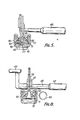
- FIGURES 6,7 and 8 uses the same slides as those shown in FIGURES 1 and 2, and the position..lock trigger 32. is similar to that trigger except that it is pivoted at 39 in the sides of the second slide member 14 and has an inverted 'U' portion 38 by means of which it can be lifted out of engagement with the notches 31, (FIGURE 6).
- Lifting of the trigger 32 is by means of a composite operating member comprising a control knob 49 in the form of an injection moulding, a cross tube 47, and a 'U' shaped wire 48 with the 'U' end swaged into the end of the cross tube 47.
- the components are supplied in knock-down form with the slides, and in assembly the cross tube is first fitted to the second slide member 14 by pushing the ends of the wire.48 respectively into a pivot hole 51 and a guide slot 52-formed in the double walls 22 of the second slide member 14.
- the wire ends protrude through to the other side of the double member 22 and the control knob 49 can be press-fitted onto those ends, as shown best in FIGURE 8 to hold the components assembled.
- the corresponding part of the control knob is formed with two press fit holes for that purpose.
Landscapes
- Engineering & Computer Science (AREA)
- Aviation & Aerospace Engineering (AREA)
- Transportation (AREA)
- Mechanical Engineering (AREA)
- Seats For Vehicles (AREA)
Applications Claiming Priority (4)
| Application Number | Priority Date | Filing Date | Title |
|---|---|---|---|
| GB8126491 | 1981-09-01 | ||
| GB8126491 | 1981-09-01 | ||
| GB08216171A GB2107575B (en) | 1981-09-01 | 1982-06-03 | Vehicle seat slides |
| GB8216171 | 1982-06-03 |
Publications (2)
| Publication Number | Publication Date |
|---|---|
| EP0076041A1 true EP0076041A1 (de) | 1983-04-06 |
| EP0076041B1 EP0076041B1 (de) | 1986-03-19 |
Family
ID=26280615
Family Applications (1)
| Application Number | Title | Priority Date | Filing Date |
|---|---|---|---|
| EP19820304575 Expired EP0076041B1 (de) | 1981-09-01 | 1982-08-31 | Fahrzeugsitzverstellvorrichtung |
Country Status (3)
| Country | Link |
|---|---|
| EP (1) | EP0076041B1 (de) |
| DE (1) | DE3269991D1 (de) |
| GB (1) | GB2107575B (de) |
Cited By (25)
| Publication number | Priority date | Publication date | Assignee | Title |
|---|---|---|---|---|
| DE3221959A1 (de) * | 1982-06-11 | 1983-12-15 | Keiper Automobiltechnik Gmbh & Co Kg, 5630 Remscheid | Sitzschiene |
| WO1986000857A1 (fr) * | 1984-07-26 | 1986-02-13 | Schweizerische Aluminium Ag | Dispositif de support d'un siege coulissant dans un vehicule |
| EP0111674A3 (en) * | 1982-12-16 | 1986-07-02 | Keiper Recaro Gmbh & Co. | Seat, in particular for a motor vehicle |
| EP0100880A3 (en) * | 1982-07-16 | 1986-10-29 | Keiper Recaro Gmbh & Co. | Seat glide for the longitudinal adjustment of vehicle seats |
| DE3631780A1 (de) * | 1985-09-20 | 1987-04-02 | Toyota Motor Co Ltd | Sitzschiene mit eingebautem gurtanker |
| DE3631791A1 (de) * | 1985-09-20 | 1987-04-09 | Toyota Motor Co Ltd | Sitzschiene mit eingearbeitetem gurtanker |
| FR2606338A1 (fr) * | 1986-11-07 | 1988-05-13 | Tachi S Co | Dispositif de coulissement pour sieges, notamment pour sieges de vehicules automobiles |
| EP0197638A3 (en) * | 1985-02-22 | 1989-02-15 | T.I. Cox Limited | Vehicle seat adjustment system |
| US4821991A (en) * | 1986-04-07 | 1989-04-18 | Nissan Motor Co., Ltd. | Seat slide device |
| DE4201354A1 (de) * | 1991-01-21 | 1992-07-23 | Aisin Seiki | Fahrzeugsitz-einstellvorrichtung |
| DE4133509A1 (de) * | 1991-10-10 | 1993-04-15 | Keiper Recaro Gmbh Co | Fuehrungsschienenanordnung fuer einen in waehlbaren laengslagen feststellbaren sitz, insbesondere kraftfahrzeugsitz |
| US5529397A (en) * | 1994-06-15 | 1996-06-25 | Aisin Seiki Kabushiki Kaisha | Seat slide device |
| EP0753425A1 (de) * | 1995-07-12 | 1997-01-15 | Cesa Compagnie Europeenne De Sieges Pour Automobiles | Vorrichtung zum Längsverstellen von Kraftfahrzeugsitzen |
| US5676341A (en) * | 1995-03-20 | 1997-10-14 | Delta Kogyo Co., Ltd. | Vehicle seat slide mechanism |
| US5692839A (en) * | 1995-11-14 | 1997-12-02 | Bertrand Faure Equipements Sa | Vehicle seat slide |
| FR2762555A1 (fr) | 1997-04-26 | 1998-10-30 | Hammerstein Gmbh C Rob | Guidage longitudinal pour un siege de vehicule, comprenant deux rails oblongs et des moyens de guidage |
| EP0878342A1 (de) * | 1997-05-13 | 1998-11-18 | Delta Kogyo Co., Ltd. | Fahrzeugsitzverstellschienen |
| DE3645261C2 (de) * | 1985-09-20 | 1999-01-21 | Toyota Motor Co Ltd | Verriegelungsvorrichtung für eine Sitzschieneneinheit |
| WO1999011487A1 (en) | 1997-08-28 | 1999-03-11 | Lear Corporation | Method and apparatus for seat track construction |
| GB2333229A (en) * | 1997-08-28 | 1999-07-21 | Lear Corp | Method and apparatus for seat track construction |
| US6116561A (en) * | 1998-08-28 | 2000-09-12 | Lear Corporation | Method and apparatus for seat track construction |
| FR2802483A1 (fr) * | 1999-12-17 | 2001-06-22 | Aisin Seiki | Appareil de coulissement de siege |
| RU2209738C2 (ru) * | 1997-02-13 | 2003-08-10 | Бертран Фор Экипман С.А. | Салазки для автомобильного сидения |
| FR2884462A1 (fr) * | 2005-04-18 | 2006-10-20 | Faurecia Sieges Automobile | Glissiere de siege de vehicule automobile, et procede de fabrication |
| EP1621390A3 (de) * | 2004-07-28 | 2009-04-15 | C. Rob. Hammerstein GmbH & Co.KG | Längsführung für Fahrzeugsitze |
Families Citing this family (3)
| Publication number | Priority date | Publication date | Assignee | Title |
|---|---|---|---|---|
| JPS6266830U (de) * | 1985-10-17 | 1987-04-25 | ||
| DE3705076A1 (de) * | 1987-02-18 | 1988-09-01 | Teves Gmbh Co Ohg Alfred | Kraftfahrzeugsitz |
| JP3687144B2 (ja) * | 1995-08-09 | 2005-08-24 | アイシン精機株式会社 | 車両用シートスライド装置 |
Citations (4)
| Publication number | Priority date | Publication date | Assignee | Title |
|---|---|---|---|---|
| DE2605997A1 (de) * | 1976-02-14 | 1977-08-18 | Riehle Fa Otto | Gleitfuehrung fuer in fahrzeuglaengsrichtung verschiebbare sitze |
| DE7718568U1 (de) * | 1977-06-11 | 1978-12-21 | P.A. Rentrop, Hubbert & Wagner Fahrzeugausstattungen Gmbh & Co Kg, 3060 Stadthagen | In laengsrichtung verstellbarer und arretierbarer kraftfahrzeugsitz |
| GB2033738A (en) * | 1978-09-22 | 1980-05-29 | Cox T Ltd | Improvements in or relating to vehicle seat slide mechanisms |
| EP0037726A1 (de) * | 1980-04-03 | 1981-10-14 | Ti Cox Limited | Fahrzeugsitzverstellung |
-
1982
- 1982-06-03 GB GB08216171A patent/GB2107575B/en not_active Expired
- 1982-08-31 DE DE8282304575T patent/DE3269991D1/de not_active Expired
- 1982-08-31 EP EP19820304575 patent/EP0076041B1/de not_active Expired
Patent Citations (4)
| Publication number | Priority date | Publication date | Assignee | Title |
|---|---|---|---|---|
| DE2605997A1 (de) * | 1976-02-14 | 1977-08-18 | Riehle Fa Otto | Gleitfuehrung fuer in fahrzeuglaengsrichtung verschiebbare sitze |
| DE7718568U1 (de) * | 1977-06-11 | 1978-12-21 | P.A. Rentrop, Hubbert & Wagner Fahrzeugausstattungen Gmbh & Co Kg, 3060 Stadthagen | In laengsrichtung verstellbarer und arretierbarer kraftfahrzeugsitz |
| GB2033738A (en) * | 1978-09-22 | 1980-05-29 | Cox T Ltd | Improvements in or relating to vehicle seat slide mechanisms |
| EP0037726A1 (de) * | 1980-04-03 | 1981-10-14 | Ti Cox Limited | Fahrzeugsitzverstellung |
Cited By (34)
| Publication number | Priority date | Publication date | Assignee | Title |
|---|---|---|---|---|
| DE3221959A1 (de) * | 1982-06-11 | 1983-12-15 | Keiper Automobiltechnik Gmbh & Co Kg, 5630 Remscheid | Sitzschiene |
| EP0100880A3 (en) * | 1982-07-16 | 1986-10-29 | Keiper Recaro Gmbh & Co. | Seat glide for the longitudinal adjustment of vehicle seats |
| EP0111674A3 (en) * | 1982-12-16 | 1986-07-02 | Keiper Recaro Gmbh & Co. | Seat, in particular for a motor vehicle |
| WO1986000857A1 (fr) * | 1984-07-26 | 1986-02-13 | Schweizerische Aluminium Ag | Dispositif de support d'un siege coulissant dans un vehicule |
| EP0197638A3 (en) * | 1985-02-22 | 1989-02-15 | T.I. Cox Limited | Vehicle seat adjustment system |
| DE3645261C2 (de) * | 1985-09-20 | 1999-01-21 | Toyota Motor Co Ltd | Verriegelungsvorrichtung für eine Sitzschieneneinheit |
| DE3631780A1 (de) * | 1985-09-20 | 1987-04-02 | Toyota Motor Co Ltd | Sitzschiene mit eingebautem gurtanker |
| DE3631791A1 (de) * | 1985-09-20 | 1987-04-09 | Toyota Motor Co Ltd | Sitzschiene mit eingearbeitetem gurtanker |
| US4821991A (en) * | 1986-04-07 | 1989-04-18 | Nissan Motor Co., Ltd. | Seat slide device |
| FR2606338A1 (fr) * | 1986-11-07 | 1988-05-13 | Tachi S Co | Dispositif de coulissement pour sieges, notamment pour sieges de vehicules automobiles |
| US5192045A (en) * | 1990-01-21 | 1993-03-09 | Aisin Seiki Kabushiki Kaisha | Seat slide adjuster for vehicles |
| DE4201354A1 (de) * | 1991-01-21 | 1992-07-23 | Aisin Seiki | Fahrzeugsitz-einstellvorrichtung |
| DE4133509A1 (de) * | 1991-10-10 | 1993-04-15 | Keiper Recaro Gmbh Co | Fuehrungsschienenanordnung fuer einen in waehlbaren laengslagen feststellbaren sitz, insbesondere kraftfahrzeugsitz |
| DE4133509C2 (de) * | 1991-10-10 | 1998-07-02 | Keiper Gmbh & Co | Führungsschienenanordnung für einen in wählbaren Längslagen feststellbaren Kraftfahrzeugsitz |
| US5529397A (en) * | 1994-06-15 | 1996-06-25 | Aisin Seiki Kabushiki Kaisha | Seat slide device |
| US5676341A (en) * | 1995-03-20 | 1997-10-14 | Delta Kogyo Co., Ltd. | Vehicle seat slide mechanism |
| EP0753425A1 (de) * | 1995-07-12 | 1997-01-15 | Cesa Compagnie Europeenne De Sieges Pour Automobiles | Vorrichtung zum Längsverstellen von Kraftfahrzeugsitzen |
| FR2736596A1 (fr) * | 1995-07-12 | 1997-01-17 | Cesa | Dispositif de reglage longitudinal d'un siege pour vehicule automobile |
| US5692839A (en) * | 1995-11-14 | 1997-12-02 | Bertrand Faure Equipements Sa | Vehicle seat slide |
| RU2209738C2 (ru) * | 1997-02-13 | 2003-08-10 | Бертран Фор Экипман С.А. | Салазки для автомобильного сидения |
| FR2762555A1 (fr) | 1997-04-26 | 1998-10-30 | Hammerstein Gmbh C Rob | Guidage longitudinal pour un siege de vehicule, comprenant deux rails oblongs et des moyens de guidage |
| DE19717667C5 (de) * | 1997-04-26 | 2012-05-16 | C. Rob. Hammerstein Gmbh & Co. Kg | Längsführung für Fahrzeugsitz mit zwei länglichen Schienen und Führungsmitteln |
| DE19717667B4 (de) * | 1997-04-26 | 2005-08-18 | C. Rob. Hammerstein Gmbh & Co. Kg | Längsführung für Fahrzeugsitz mit zwei länglichen Schienen und Führungsmitteln |
| EP0878342A1 (de) * | 1997-05-13 | 1998-11-18 | Delta Kogyo Co., Ltd. | Fahrzeugsitzverstellschienen |
| US6089521A (en) * | 1997-05-13 | 2000-07-18 | Delta Kogyo Co., Ltd. | Automobile seat slide unit |
| GB2333229A (en) * | 1997-08-28 | 1999-07-21 | Lear Corp | Method and apparatus for seat track construction |
| GB2333229B (en) * | 1997-08-28 | 2001-07-04 | Lear Corp | Method and apparatus for seat track construction |
| WO1999011487A1 (en) | 1997-08-28 | 1999-03-11 | Lear Corporation | Method and apparatus for seat track construction |
| US6116561A (en) * | 1998-08-28 | 2000-09-12 | Lear Corporation | Method and apparatus for seat track construction |
| FR2802483A1 (fr) * | 1999-12-17 | 2001-06-22 | Aisin Seiki | Appareil de coulissement de siege |
| EP1621390A3 (de) * | 2004-07-28 | 2009-04-15 | C. Rob. Hammerstein GmbH & Co.KG | Längsführung für Fahrzeugsitze |
| FR2884462A1 (fr) * | 2005-04-18 | 2006-10-20 | Faurecia Sieges Automobile | Glissiere de siege de vehicule automobile, et procede de fabrication |
| CN100519262C (zh) * | 2005-04-18 | 2009-07-29 | 富尔夏汽车座椅股份有限公司 | 车辆座椅的滑行装置和制造该滑行装置的方法 |
| US8146877B2 (en) | 2005-04-18 | 2012-04-03 | Faurecia Sièges d'Automobile | Runner for a motor vehicle seat, and a method of manufacturing such a runner |
Also Published As
| Publication number | Publication date |
|---|---|
| GB2107575B (en) | 1985-06-05 |
| EP0076041B1 (de) | 1986-03-19 |
| GB2107575A (en) | 1983-05-05 |
| DE3269991D1 (en) | 1986-04-24 |
Similar Documents
| Publication | Publication Date | Title |
|---|---|---|
| EP0076041B1 (de) | Fahrzeugsitzverstellvorrichtung | |
| US5772173A (en) | Lockable slide, especially for automobile vehicle seats | |
| US4664444A (en) | Seat assembly having adjustable thigh support | |
| US4804229A (en) | Seat slide device | |
| US7000880B2 (en) | Slide for motor vehicle seat | |
| US5286076A (en) | Seat slide device | |
| EP0180422B1 (de) | Sitzgleitschieneneinrichtung | |
| US3350046A (en) | Seat slide assembly for automotive vehicles | |
| GB1576170A (en) | Guide provided with a locking device for adjustable vehicle seats | |
| US6286799B1 (en) | Slide device for vehicle seat | |
| JP2892984B2 (ja) | 自動車シート用レール対 | |
| KR20060029520A (ko) | 자동차용 시트 슬라이드 장치 | |
| GB2188543A (en) | Seat slide device | |
| DE2418765B2 (de) | Fahrzeugsitz | |
| KR102271507B1 (ko) | 승합차량의 2열 독립시트용 시트 이송장치 | |
| US5755422A (en) | Automotive seat track assembly having safety locking device | |
| GB2047086A (en) | Motor vehicle seat | |
| EP0037726A1 (de) | Fahrzeugsitzverstellung | |
| GB1589126A (en) | Vehicle seats | |
| US4520982A (en) | Slide adjustment apparatus | |
| EP0135389A2 (de) | Fahrzeugsitzeinheit mit eingebauter Gleitschiene | |
| WO2007094011A2 (en) | Slider locking system with lock triggers | |
| US5520362A (en) | Master-slave vehicle seat adjuster | |
| EP0117131A2 (de) | Längsverschiebemechanik für einen Fahrzeugsitz | |
| US4392692A (en) | Seat support slide track structure |
Legal Events
| Date | Code | Title | Description |
|---|---|---|---|
| PUAI | Public reference made under article 153(3) epc to a published international application that has entered the european phase |
Free format text: ORIGINAL CODE: 0009012 |
|
| AK | Designated contracting states |
Designated state(s): DE FR GB IT SE |
|
| 17P | Request for examination filed |
Effective date: 19831006 |
|
| GRAA | (expected) grant |
Free format text: ORIGINAL CODE: 0009210 |
|
| ITF | It: translation for a ep patent filed | ||
| AK | Designated contracting states |
Kind code of ref document: B1 Designated state(s): DE FR GB IT SE |
|
| REF | Corresponds to: |
Ref document number: 3269991 Country of ref document: DE Date of ref document: 19860424 |
|
| ET | Fr: translation filed | ||
| PLBE | No opposition filed within time limit |
Free format text: ORIGINAL CODE: 0009261 |
|
| STAA | Information on the status of an ep patent application or granted ep patent |
Free format text: STATUS: NO OPPOSITION FILED WITHIN TIME LIMIT |
|
| 26N | No opposition filed | ||
| PG25 | Lapsed in a contracting state [announced via postgrant information from national office to epo] |
Ref country code: FR Effective date: 19900427 |
|
| REG | Reference to a national code |
Ref country code: FR Ref legal event code: ST |
|
| EAL | Se: european patent in force in sweden |
Ref document number: 82304575.2 |
|
| PGFP | Annual fee paid to national office [announced via postgrant information from national office to epo] |
Ref country code: SE Payment date: 20000802 Year of fee payment: 19 |
|
| PGFP | Annual fee paid to national office [announced via postgrant information from national office to epo] |
Ref country code: DE Payment date: 20010802 Year of fee payment: 20 |
|
| PGFP | Annual fee paid to national office [announced via postgrant information from national office to epo] |
Ref country code: GB Payment date: 20010803 Year of fee payment: 20 |
|
| PG25 | Lapsed in a contracting state [announced via postgrant information from national office to epo] |
Ref country code: SE Free format text: LAPSE BECAUSE OF NON-PAYMENT OF DUE FEES Effective date: 20010901 |
|
| REG | Reference to a national code |
Ref country code: GB Ref legal event code: IF02 |
|
| EUG | Se: european patent has lapsed |
Ref document number: 82304575.2 |
|
| PG25 | Lapsed in a contracting state [announced via postgrant information from national office to epo] |
Ref country code: GB Free format text: LAPSE BECAUSE OF EXPIRATION OF PROTECTION Effective date: 20020830 |
|
| REG | Reference to a national code |
Ref country code: GB Ref legal event code: PE20 Effective date: 20020830 |