EP0076046A1 - Extrémité de câble de puissance haute tension à trou nervure de connecteur - Google Patents
Extrémité de câble de puissance haute tension à trou nervure de connecteur Download PDFInfo
- Publication number
- EP0076046A1 EP0076046A1 EP82304670A EP82304670A EP0076046A1 EP 0076046 A1 EP0076046 A1 EP 0076046A1 EP 82304670 A EP82304670 A EP 82304670A EP 82304670 A EP82304670 A EP 82304670A EP 0076046 A1 EP0076046 A1 EP 0076046A1
- Authority
- EP
- European Patent Office
- Prior art keywords
- bore
- cable
- conductor
- terminator
- ridge
- Prior art date
- Legal status (The legal status is an assumption and is not a legal conclusion. Google has not performed a legal analysis and makes no representation as to the accuracy of the status listed.)
- Withdrawn
Links
- 239000004020 conductor Substances 0.000 claims abstract description 63
- 230000006835 compression Effects 0.000 claims abstract description 11
- 238000007906 compression Methods 0.000 claims abstract description 11
- 239000003989 dielectric material Substances 0.000 claims description 3
- 238000009413 insulation Methods 0.000 description 13
- 239000012212 insulator Substances 0.000 description 8
- 229910052782 aluminium Inorganic materials 0.000 description 6
- XAGFODPZIPBFFR-UHFFFAOYSA-N aluminium Chemical compound [Al] XAGFODPZIPBFFR-UHFFFAOYSA-N 0.000 description 6
- 239000004411 aluminium Substances 0.000 description 4
- 239000000945 filler Substances 0.000 description 4
- 239000000463 material Substances 0.000 description 4
- PNEYBMLMFCGWSK-UHFFFAOYSA-N Alumina Chemical compound [O-2].[O-2].[O-2].[Al+3].[Al+3] PNEYBMLMFCGWSK-UHFFFAOYSA-N 0.000 description 3
- 238000003780 insertion Methods 0.000 description 3
- 230000037431 insertion Effects 0.000 description 3
- 229920000181 Ethylene propylene rubber Polymers 0.000 description 2
- 239000003963 antioxidant agent Substances 0.000 description 2
- 230000003078 antioxidant effect Effects 0.000 description 2
- 235000006708 antioxidants Nutrition 0.000 description 2
- 230000015556 catabolic process Effects 0.000 description 2
- 238000013461 design Methods 0.000 description 2
- 229910052751 metal Inorganic materials 0.000 description 2
- 239000002184 metal Substances 0.000 description 2
- 229920001296 polysiloxane Polymers 0.000 description 2
- 229910052573 porcelain Inorganic materials 0.000 description 2
- 229910000881 Cu alloy Inorganic materials 0.000 description 1
- 229920002595 Dielectric elastomer Polymers 0.000 description 1
- ATJFFYVFTNAWJD-UHFFFAOYSA-N Tin Chemical compound [Sn] ATJFFYVFTNAWJD-UHFFFAOYSA-N 0.000 description 1
- 230000005540 biological transmission Effects 0.000 description 1
- 230000015572 biosynthetic process Effects 0.000 description 1
- 238000005266 casting Methods 0.000 description 1
- 239000000919 ceramic Substances 0.000 description 1
- 238000004140 cleaning Methods 0.000 description 1
- 230000000295 complement effect Effects 0.000 description 1
- 238000002788 crimping Methods 0.000 description 1
- 238000005520 cutting process Methods 0.000 description 1
- 229920001198 elastomeric copolymer Polymers 0.000 description 1
- 239000013536 elastomeric material Substances 0.000 description 1
- 239000003822 epoxy resin Substances 0.000 description 1
- 239000006261 foam material Substances 0.000 description 1
- 239000011521 glass Substances 0.000 description 1
- 239000004519 grease Substances 0.000 description 1
- LNEPOXFFQSENCJ-UHFFFAOYSA-N haloperidol Chemical compound C1CC(O)(C=2C=CC(Cl)=CC=2)CCN1CCCC(=O)C1=CC=C(F)C=C1 LNEPOXFFQSENCJ-UHFFFAOYSA-N 0.000 description 1
- 238000005304 joining Methods 0.000 description 1
- 239000000314 lubricant Substances 0.000 description 1
- 238000000034 method Methods 0.000 description 1
- 239000000203 mixture Substances 0.000 description 1
- 238000012986 modification Methods 0.000 description 1
- 230000004048 modification Effects 0.000 description 1
- 230000007935 neutral effect Effects 0.000 description 1
- 230000003647 oxidation Effects 0.000 description 1
- 238000007254 oxidation reaction Methods 0.000 description 1
- 239000002245 particle Substances 0.000 description 1
- 229920003217 poly(methylsilsesquioxane) Polymers 0.000 description 1
- 229920000647 polyepoxide Polymers 0.000 description 1
- 238000002360 preparation method Methods 0.000 description 1
- 230000005855 radiation Effects 0.000 description 1
- 238000007789 sealing Methods 0.000 description 1
- HBMJWWWQQXIZIP-UHFFFAOYSA-N silicon carbide Chemical compound [Si+]#[C-] HBMJWWWQQXIZIP-UHFFFAOYSA-N 0.000 description 1
- 229910010271 silicon carbide Inorganic materials 0.000 description 1
- 239000000126 substance Substances 0.000 description 1
- 238000012360 testing method Methods 0.000 description 1
- 238000012546 transfer Methods 0.000 description 1
- 239000011800 void material Substances 0.000 description 1
Images
Classifications
-
- H—ELECTRICITY
- H01—ELECTRIC ELEMENTS
- H01R—ELECTRICALLY-CONDUCTIVE CONNECTIONS; STRUCTURAL ASSOCIATIONS OF A PLURALITY OF MUTUALLY-INSULATED ELECTRICAL CONNECTING ELEMENTS; COUPLING DEVICES; CURRENT COLLECTORS
- H01R4/00—Electrically-conductive connections between two or more conductive members in direct contact, i.e. touching one another; Means for effecting or maintaining such contact; Electrically-conductive connections having two or more spaced connecting locations for conductors and using contact members penetrating insulation
- H01R4/28—Clamped connections, spring connections
- H01R4/30—Clamped connections, spring connections utilising a screw or nut clamping member
- H01R4/36—Conductive members located under tip of screw
-
- H—ELECTRICITY
- H02—GENERATION; CONVERSION OR DISTRIBUTION OF ELECTRIC POWER
- H02G—INSTALLATION OF ELECTRIC CABLES OR LINES, OR OF COMBINED OPTICAL AND ELECTRIC CABLES OR LINES
- H02G15/00—Cable fittings
- H02G15/02—Cable terminations
- H02G15/06—Cable terminating boxes, frames or other structures
-
- H—ELECTRICITY
- H01—ELECTRIC ELEMENTS
- H01R—ELECTRICALLY-CONDUCTIVE CONNECTIONS; STRUCTURAL ASSOCIATIONS OF A PLURALITY OF MUTUALLY-INSULATED ELECTRICAL CONNECTING ELEMENTS; COUPLING DEVICES; CURRENT COLLECTORS
- H01R4/00—Electrically-conductive connections between two or more conductive members in direct contact, i.e. touching one another; Means for effecting or maintaining such contact; Electrically-conductive connections having two or more spaced connecting locations for conductors and using contact members penetrating insulation
- H01R4/28—Clamped connections, spring connections
- H01R4/38—Clamped connections, spring connections utilising a clamping member acted on by screw or nut
- H01R4/46—Clamping area between two screws placed side by side
Definitions
- the present inventicn relates to electrical terminators or potheads and more particularly to improved hood lugs for terminators which more securely hold the electrical conductor.
- Electrical cable such as that used for underground transmission, is typically comprised of a multistranded electrical conductor, a dielectric insulation layer encasing the conductor, and a shield layer surrounding the insulation layer, the shield being at ground potential.
- the dielectric insulation layer provides a radial voltage gradient between the conductor and the grounded shield.
- Aerial cable is generally unshielded as the amount of electrical loss through the air does not justify the cost of shielding.
- a common type of terminator has an insulating body with an axial passageway through which an insulated, but unshielded, prepared end of cable extends.
- An annular dielectric layer within the bore and surrounding a portion of the prepared cable end relieves electrical stress between the end portion of the conductor and the shield.
- the very end of the cable is stripped of insulation, and the exposed conductor end extends beyond the terminator body into an attached connector lug which electrically connects the conductor to the aerial cable.
- the connector lug includes a hood portion, which fits over and electrically contacts the exposed end of the conductor, and an extension or protruberance for attachment of the aerial cable.
- the prepared cable is held within the terminator primarily by the clamping of the exposed conductor end within the hood.
- the exposed conductor may be held by crimping or, preferably, by set screws received in threaded openings in the hood as described in U.S. Patents Nos. 3,290,428 and 3,796,821.
- the set screws which are tightened against the conductor and which may be adjusted to grip conductors within a range of diameters, are the preferred method of clamping a conductor end within a terminator.
- the set screws are tightened to deform the strands of the conductor conforming the conductor to the inner walls of the bore.
- the frictional engagement of the set screws with the conductor serves not only to hold the ends of the cables together but provides the electrical contact of the cable with the connector lug, and the importance of achieving and maintaining secure engagement of the cable portions within the hood and good electrical contact therebetween may be easily appreciated.
- a terminator embodying the invention may be provided for a prepared end of a shielded cable having a connector lug at its aerial end which provides for improved gripping of the end of the shielded cable and better electrical contact.
- the connector lug which seals off the aerial end of the terminator body and connects the shielded cable to the aerial cable, has a hood portion with a closed bore for receiving the exposed conductor end of the shielded cable, threaded openings into the sidewall of the bore which receive threaded set screws, and ridges extending inward from the sidewall of the closed bore opposite the threaded openings whereby a more secure compression fit is achieved when the set screws are tightened to bear against the exposed end of the conductor.
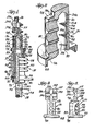
- An improved connector lug 10 is provided for an electrical terminator 12 which joins a shielded cable 14 with an aerial conductor 16, the improved connector lug increasing the pull-out strength of the terminator-cable connection and lowering electrical resistance between the connector lug and the conductor 18.
- the connector lug has a closed bore 20 coextensive with a bore or passageway 22 through the body 24 of the terminator 12 for receiving the exposed end 26 of the conductor 18 ahd threaded openings 28 through the side of the closed bore 20 in which cooperating set screws 30 are received for forming a compression fit with the exposed conductor end.
- the improved physical and electrical connection is achieved by providing ridges 32 extending inward of the closed bore 20 generally opposite the bearing surfaces 34 of the set screws 30 whereby the exposed end 26 of the conductor 18 is deformed along the ridged sidewall 38 achieving a superior compression fit.
- the end of a shielded power cable 14 has a terminator 12 applied thereon in telescopic relationship with an electrical stress relief element 46 surrounding the cable at the base end of the terminator.
- the terminator 12 includes the rigid body or housing 24, a mounting plate 40 at its base end 42, the connector lug 10 at its aerial end 44, and a filler layer 47 which fills the space intermediate the stress relief element 46 and portions of the insulator body.
- the shielded cable 14 includes the conductor 18, dielectric insulation 48 surrounding and encasing the conductor, a shield layer 50 surrounding the dielectric insulation and concentric neutral or ground wires 52 wound around and in contact with the shield layer.
- the ground wires 52 are initially removed from a portion of the end of the shield and bound to form a common ground wire 54 for subsequent connection to the mounting plate 40.
- the shield 50 is stripped beyond the bound ground wires 52 leaving a length of exposed shield, and the insulation 48 is stripped beyond the end of the shield to expose the end of the conductor 18 and leave an intermediate length of exposed insulation.
- high dielectric splicing tape is tightly layered around portions of the exposed insulation 48 in a generally tubular configuration.
- the end of the stress relief element adjacent the shield layer 50 is optionally bound with PVC binding tape 51 that helps to maintain the stress relief element in place as the prepared cable is inserted in the terminator 12.
- a lubricant such as a silicone grease
- An abrasive anti-oxidant is applied to the exposed conductor 18.
- the terminator 12 is then slipped over the prepared cable end until the exposed end 26 of the conductor 18 extends beyond the terminator body 24 into the hood portion 19 of the lug 10 and the dielectric insulation 48 extends closely adjacent the aerial end,44,of the body 24.
- the set screws 30 are torqued to provide a compression fit between the conductor 18 and the sidewall 38 of the closed bore 20, and the aerial conductor 16 is connected to an extension 57 of the connector lug 10.
- porcelain is generally used for the rigid insulator body 24 because it is a self-cleaning, inorganic, homogeneous material which does not carbonize when subjected to leakage currents and is not subject to weathering, radiation, or chemical damage. Porcelain also has high tracking resistance, i.e., the ability of the material to resist the formation of a conductive path by an arc adjacent its surface. Additional materials, however, such as other ceramics, glass and epoxy resins, also may be suitable for the insulator body.
- the outside surface 60 of the rigid insulator body 24 is finned or corrugated in a conventional manner to increase the creepage distance along the surface between the lug 10 (100% potential) and the mounting plate 40 (0% potential).
- the inner surface of the rigid insulator body 24 is smooth and includes a surface 62 formed by the general axial passageway 22 therethrough.
- the preferred splicing tape used to form the stress relief element 46 in high voltage terminators is comprised. of a heavy paste of silicon carbide particles on an ethylene-propylene rubber backing.
- the stress relief element 46 might be a tube of closed cell elastomeric dielectric material having an inner diameter proportioned to provide an interference fit around the insulation layer 48.
- the filler element 47 is formed of a compressible foam material proportioned to fill the void between the stress relief element 46 and the insulator body 24 helping to avoid dielectric breakdown.
- the compressible filler layer 47 accommodates stress relief layers 46 within a range of diameters and maintains a void-free fit as the cable expands and contracts with temperature change.
- the filler element 47 is preferably formed of dielectric elastomers such as silicones,, ethylene-propylene rubbers and fluorinated elastomeric copolymers.
- Both the mounting plate 40 and the connector lug 10 are made of metal, such as copper alloy or aluminum, and both are firmly applied to the insulator body. As shown, both the mounting plate 40 and the connector lug 10 have deformable cylindrical attachment members 66, 68 which are rolled over annular lips 70, 72 at the respective ends 42, 44 of the terminator body 24. Sealing gaskets 74, 76 of suitable elastomeric material are held against the ends 42, 44 of the body by the mounting plate 40 and the connector lug 10.
- the connector lug 10 is formed of a single piece of cast metal, preferably aluminum, and includes the hood portion 19 for connection to:the insulator body 24 and to the exposed end 26 of the shielded cable 14 and an extension 57 from its aerial end which has a surface on which the aerial conductor 16 is mounted and clamped.
- the one piece casting provides good thermal dissipation because there are no thermal interfaces in metallic parts to provide increased resistance to heat transfer.
- the hood portion 19 is generally cylindrical but has a protrusion 94 along one side through which the set screw openings 28 are bored. The protrusion 94 provides for elongated openings 28 with sufficient threads for holding the required set screw torque.
- the hood portion 90 has an annular flange 96 at its base end from which the cylindrical attachment member 68 extends.
- the closed bore 20 extends axially from the base end of the hood portion 19 coextensive with the terminator body passageway 22 and has a diameter appropriate for receiving an exposed conductor end 26 within a given diameter range.
- the threaded openings 28 extend through the protrusion 94 of the hood portion 19 generally perpendicular to the axis of the bore 20, and the matched set screws 30 are received therein, the bearing surfaces 34 of the set screws forming a compression fit for holding the exposed end 26 of the conductor 18.
- At least one set screw 30 is required, but it is preferred that several set screws be provided spaced apart axially relative to the bore 20 and mutually parallel.
- the set screws 30 are tightened to bear against the conductor 18 and hold the conductor between the bearing surfaces 34 of the set screws 30 and the opposite side of the bore.
- the strands of a stranded conductor 18 are deformed outward by the tightening of the set screws 30 to conform the conductor to the sidewall 38 of the bore 20.
- the connector lug 10 of the embodiment provides improved interference fit through the ridges 32 extending inward from a portion 38b of the sidewall 38 opposite the bearing surfaces 34 of the set screws 30.
- the ridges 32 are disposed generally midway between the axes of adjacent threaded openings 28.
- the sidewall portion 38b opposite the threaded openings is enlarged to extend radially outward giving the sidewalls 38 a generally oval shape and leaving the ridges 32 with inner rims 106 which are continuous of the circular cross-section of the sidewall portion 38a through which the threaded opening 28 extend.
- the ridges have their greatest height, i.e., about l/16th inch, relative to the enlarged sidewall portion 38b at their midpoints and blend into the sidewall 38 at their ends.
- the ridges 32 each have sloped sides 104, 105 (FIG. 2) which angle inward from the enlarged sidewall portion 38b preferably. at an angle of about 30° t Q about 70°.
- the side 104 of each ridge toward the aerial end has the steeper slope, i.e., between about 50° and about 70° relative to the enlarged sidewall portion 38b while the side 105 toward the base end has a more gentle slope, i.e., between about 30° and about 45°..
- the bared end 26 of the conductor 18 is inserted axially into the bore of the lug through the cylindrical passageway defined by the rims 106 of the ridges and the circular sidewall portion 38. If during insertion, the conductor 18 contacts the rims 106 or gently sloped sides 105, of the ridges, it glances. thereover and inserts easily into the lug.
- the deformation of the conductor 18 along the ridges 31 and valleys 110 of the enlarged sidewall portion 38b increases the surface contact between the conductor and the sidewall reducing electrical resistance therebetween and consequent heat build-up in the connector lug 10.
- the ridges 32 also improve the electrical connection between the conductor 18 and the connector lug by providing a conductor-lug interface more resistant to oxide buildup.
- a difficulty with aluminium electrical fittings is the buildup of the layer of oxide which inevitably occurs when aluminium is exposed to air.
- the lug 10 is preferably tin plated, and the conductor 18 is commonly coated with an abrasive anti-oxidant material such as that sold under the trade name Penetrox.
- the extension 57 provides surfaces appropriate for joining the shielded cable to a second cable 16 such as an aerial conductor or an electrical bus bar (not shown) and will have the configuration required for the application.
- the extension 57 (FIGS. 3,4) is a generally square plate 122 having a flat back surface 124 which may be connected to a bus bar and a front surface 126 with intersecting semi cylindrical troughs 128, 130 for receiving the end of an aerial conductor 16 either axially or transversely.
- a first trough 128 has an axis along or generally parallel to the axis of the terminator, and the second trough 130 has an axis generally transverse to the terminator axis.
- Four holes 132 are provided along the intersecting troughs through which a pair of U-bolts 134 may be inserted to attach a clamp type lug 136 with a complementary half cylindrical trough 138 in an interference fit with the aerial conductor 16.
Landscapes
- Connections By Means Of Piercing Elements, Nuts, Or Screws (AREA)
- Cable Accessories (AREA)
- Details Of Connecting Devices For Male And Female Coupling (AREA)
- Multi-Conductor Connections (AREA)
Applications Claiming Priority (2)
| Application Number | Priority Date | Filing Date | Title |
|---|---|---|---|
| US30539281A | 1981-09-25 | 1981-09-25 | |
| US305392 | 1999-05-05 |
Publications (1)
| Publication Number | Publication Date |
|---|---|
| EP0076046A1 true EP0076046A1 (fr) | 1983-04-06 |
Family
ID=23180601
Family Applications (1)
| Application Number | Title | Priority Date | Filing Date |
|---|---|---|---|
| EP82304670A Withdrawn EP0076046A1 (fr) | 1981-09-25 | 1982-09-06 | Extrémité de câble de puissance haute tension à trou nervure de connecteur |
Country Status (4)
| Country | Link |
|---|---|
| EP (1) | EP0076046A1 (fr) |
| JP (1) | JPS5866515A (fr) |
| CA (1) | CA1184266A (fr) |
| MX (1) | MX152849A (fr) |
Citations (6)
| Publication number | Priority date | Publication date | Assignee | Title |
|---|---|---|---|---|
| US2015896A (en) * | 1934-08-20 | 1935-10-01 | H B Sherman Mfg Company | Solderless connector lug for cables and the like |
| US2068152A (en) * | 1934-03-03 | 1937-01-19 | Trumbull Electric Mfg Co | Solderless electrical terminal |
| US2285529A (en) * | 1940-02-23 | 1942-06-09 | G & W Electric Speciality Co | Electrical connection for potheads and method of forming same |
| US3290428A (en) * | 1965-03-29 | 1966-12-06 | Joslyn Mfg & Supply Co | Method and apparatus for cable connection |
| FR2038410A1 (fr) * | 1969-04-12 | 1971-01-08 | Bassani Spa | |
| US3796821A (en) * | 1972-10-06 | 1974-03-12 | G & W Electric Speciality Co | High voltage cable termination |
Family Cites Families (4)
| Publication number | Priority date | Publication date | Assignee | Title |
|---|---|---|---|---|
| JPS423409Y1 (fr) * | 1964-06-17 | 1967-02-28 | ||
| JPS435799Y1 (fr) * | 1965-02-24 | 1968-03-13 | ||
| JPS5141180U (fr) * | 1974-09-20 | 1976-03-26 | ||
| US4046958A (en) * | 1976-01-07 | 1977-09-06 | Joslyn Mfg. And Supply Co. | Cable termination connector assembly and method |
-
1982
- 1982-09-06 EP EP82304670A patent/EP0076046A1/fr not_active Withdrawn
- 1982-09-15 CA CA000411512A patent/CA1184266A/fr not_active Expired
- 1982-09-24 JP JP57166439A patent/JPS5866515A/ja active Pending
- 1982-09-24 MX MX194502A patent/MX152849A/es unknown
Patent Citations (6)
| Publication number | Priority date | Publication date | Assignee | Title |
|---|---|---|---|---|
| US2068152A (en) * | 1934-03-03 | 1937-01-19 | Trumbull Electric Mfg Co | Solderless electrical terminal |
| US2015896A (en) * | 1934-08-20 | 1935-10-01 | H B Sherman Mfg Company | Solderless connector lug for cables and the like |
| US2285529A (en) * | 1940-02-23 | 1942-06-09 | G & W Electric Speciality Co | Electrical connection for potheads and method of forming same |
| US3290428A (en) * | 1965-03-29 | 1966-12-06 | Joslyn Mfg & Supply Co | Method and apparatus for cable connection |
| FR2038410A1 (fr) * | 1969-04-12 | 1971-01-08 | Bassani Spa | |
| US3796821A (en) * | 1972-10-06 | 1974-03-12 | G & W Electric Speciality Co | High voltage cable termination |
Also Published As
| Publication number | Publication date |
|---|---|
| MX152849A (es) | 1986-06-18 |
| JPS5866515A (ja) | 1983-04-20 |
| CA1184266A (fr) | 1985-03-19 |
Similar Documents
| Publication | Publication Date | Title |
|---|---|---|
| CA1110724A (fr) | Assemblage de connecteur de terminaison de cable | |
| US4161012A (en) | High voltage protection apparatus | |
| US3796821A (en) | High voltage cable termination | |
| EP0093524B1 (fr) | Presse-étoupes pour câble électrique | |
| US3800064A (en) | Universal power cable joint with closed-cell sponge stress relief element | |
| US6817897B2 (en) | End connector for coaxial cable | |
| EP0750376A2 (fr) | Presse-étoupe de terminaison pour câble électrique | |
| US4629277A (en) | Electrical apparatus | |
| US4551915A (en) | Method for terminating a high voltage cable | |
| US11424608B2 (en) | Devices and methods for electrical cable splices | |
| US4837409A (en) | Submerisible insulated splice assemblies | |
| EP0604117B1 (fr) | Presse-étoupe mis à la terre | |
| US6692299B1 (en) | Electrical connector for coaxial cable | |
| CA1041625A (fr) | Joint universel pour cables d'alimentation a isolements divers | |
| GB2130446A (en) | Cable gland seal arrangement | |
| JP2002270326A (ja) | ワイヤコネクタを作る方法、ワイヤコネクタ及び低電気抵抗接続を作る方法 | |
| US5646370A (en) | Permanent attachment of grounding wire | |
| CN101341632B (zh) | 整体连接装置 | |
| EP1253692B1 (fr) | Terminal d'un câble moyenne tension | |
| JP4659773B2 (ja) | ケーブル終端接続部 | |
| US6948955B2 (en) | Terminal of a medium voltage electrical cable | |
| CA1184266A (fr) | Terminaison de cable d'alimentation haute tension avec connecteur a ame cannelee | |
| JP6628245B2 (ja) | アルミニウム導体ケーブルの端末接続部 | |
| US4517407A (en) | High voltage cable terminator and method of assembly | |
| JP7124750B2 (ja) | プラグインコネクタ及び接続構造 |
Legal Events
| Date | Code | Title | Description |
|---|---|---|---|
| PUAI | Public reference made under article 153(3) epc to a published international application that has entered the european phase |
Free format text: ORIGINAL CODE: 0009012 |
|
| AK | Designated contracting states |
Designated state(s): AT BE CH DE FR GB IT LI LU NL SE |
|
| 17P | Request for examination filed |
Effective date: 19830901 |
|
| STAA | Information on the status of an ep patent application or granted ep patent |
Free format text: STATUS: THE APPLICATION HAS BEEN WITHDRAWN |
|
| 18W | Application withdrawn |
Withdrawal date: 19850207 |
|
| RIN1 | Information on inventor provided before grant (corrected) |
Inventor name: FOX, JAMES WILLIAM |