EP0076053A2 - Verbindungsstück für optische Fasern - Google Patents
Verbindungsstück für optische Fasern Download PDFInfo
- Publication number
- EP0076053A2 EP0076053A2 EP82304755A EP82304755A EP0076053A2 EP 0076053 A2 EP0076053 A2 EP 0076053A2 EP 82304755 A EP82304755 A EP 82304755A EP 82304755 A EP82304755 A EP 82304755A EP 0076053 A2 EP0076053 A2 EP 0076053A2
- Authority
- EP
- European Patent Office
- Prior art keywords
- fiber
- members
- fibers
- elongated members
- elongated
- Prior art date
- Legal status (The legal status is an assumption and is not a legal conclusion. Google has not performed a legal analysis and makes no representation as to the accuracy of the status listed.)
- Ceased
Links
- 239000013307 optical fiber Substances 0.000 title claims abstract description 25
- 239000000835 fiber Substances 0.000 claims abstract description 104
- 230000001681 protective effect Effects 0.000 claims abstract description 13
- 230000000712 assembly Effects 0.000 claims abstract description 8
- 238000000429 assembly Methods 0.000 claims abstract description 8
- 239000011521 glass Substances 0.000 claims abstract description 8
- 239000003365 glass fiber Substances 0.000 claims abstract description 8
- 238000004891 communication Methods 0.000 claims abstract description 4
- 239000000463 material Substances 0.000 claims description 3
- 239000002184 metal Substances 0.000 claims description 3
- 239000004033 plastic Substances 0.000 description 4
- 238000005253 cladding Methods 0.000 description 3
- 230000003287 optical effect Effects 0.000 description 3
- 239000004593 Epoxy Substances 0.000 description 2
- 101000793686 Homo sapiens Azurocidin Proteins 0.000 description 2
- 239000000853 adhesive Substances 0.000 description 2
- 230000001070 adhesive effect Effects 0.000 description 2
- 238000009413 insulation Methods 0.000 description 2
- 230000014759 maintenance of location Effects 0.000 description 2
- 230000002093 peripheral effect Effects 0.000 description 2
- 238000005299 abrasion Methods 0.000 description 1
- 238000010521 absorption reaction Methods 0.000 description 1
- 230000005540 biological transmission Effects 0.000 description 1
- 239000011248 coating agent Substances 0.000 description 1
- 238000000576 coating method Methods 0.000 description 1
- 238000010276 construction Methods 0.000 description 1
- 230000000694 effects Effects 0.000 description 1
- 125000003700 epoxy group Chemical group 0.000 description 1
- 230000003993 interaction Effects 0.000 description 1
- 230000013011 mating Effects 0.000 description 1
- 238000000034 method Methods 0.000 description 1
- 229920000647 polyepoxide Polymers 0.000 description 1
- 230000000135 prohibitive effect Effects 0.000 description 1
- 239000011253 protective coating Substances 0.000 description 1
- 230000003014 reinforcing effect Effects 0.000 description 1
- 230000000717 retained effect Effects 0.000 description 1
- 230000007704 transition Effects 0.000 description 1
Images


Classifications
-
- G—PHYSICS
- G02—OPTICS
- G02B—OPTICAL ELEMENTS, SYSTEMS OR APPARATUS
- G02B6/00—Light guides; Structural details of arrangements comprising light guides and other optical elements, e.g. couplings
- G02B6/24—Coupling light guides
- G02B6/36—Mechanical coupling means
- G02B6/38—Mechanical coupling means having fibre to fibre mating means
- G02B6/3807—Dismountable connectors, i.e. comprising plugs
- G02B6/3833—Details of mounting fibres in ferrules; Assembly methods; Manufacture
- G02B6/3834—Means for centering or aligning the light guide within the ferrule
- G02B6/3841—Means for centering or aligning the light guide within the ferrule using rods, balls for light guides
-
- G—PHYSICS
- G02—OPTICS
- G02B—OPTICAL ELEMENTS, SYSTEMS OR APPARATUS
- G02B6/00—Light guides; Structural details of arrangements comprising light guides and other optical elements, e.g. couplings
- G02B6/24—Coupling light guides
- G02B6/25—Preparing the ends of light guides for coupling, e.g. cutting
-
- G—PHYSICS
- G02—OPTICS
- G02B—OPTICAL ELEMENTS, SYSTEMS OR APPARATUS
- G02B6/00—Light guides; Structural details of arrangements comprising light guides and other optical elements, e.g. couplings
- G02B6/24—Coupling light guides
- G02B6/36—Mechanical coupling means
- G02B6/38—Mechanical coupling means having fibre to fibre mating means
- G02B6/3807—Dismountable connectors, i.e. comprising plugs
- G02B6/381—Dismountable connectors, i.e. comprising plugs of the ferrule type, e.g. fibre ends embedded in ferrules, connecting a pair of fibres
- G02B6/3817—Dismountable connectors, i.e. comprising plugs of the ferrule type, e.g. fibre ends embedded in ferrules, connecting a pair of fibres containing optical and electrical conductors
-
- G—PHYSICS
- G02—OPTICS
- G02B—OPTICAL ELEMENTS, SYSTEMS OR APPARATUS
- G02B6/00—Light guides; Structural details of arrangements comprising light guides and other optical elements, e.g. couplings
- G02B6/24—Coupling light guides
- G02B6/36—Mechanical coupling means
- G02B6/38—Mechanical coupling means having fibre to fibre mating means
- G02B6/3807—Dismountable connectors, i.e. comprising plugs
- G02B6/3873—Connectors using guide surfaces for aligning ferrule ends, e.g. tubes, sleeves, V-grooves, rods, pins, balls
- G02B6/3874—Connectors using guide surfaces for aligning ferrule ends, e.g. tubes, sleeves, V-grooves, rods, pins, balls using tubes, sleeves to align ferrules
- G02B6/3875—Floatingly supported sleeves
Definitions
- the present invention relates generally to a connector for use with optical fibers and, more particularly, to an improved connector which can be used to effect connection between optical fibers under field conditions.
- Optical fibers are relatively small glass or plastic fibers (e.g., several thousandths of an inch in diameter) which are being widely used for the transmission of optical signals to a remote location for processing or other utilisation.
- glass or plastic fibers e.g., several thousandths of an inch in diameter
- satisfactory interconnection of two such fibers requires that the fiber ends be faced off at right angles, with the facing ends aligned and brought into close proximity. It is also important that the two fibers not actually touch one another as this may cause their end portions to be distorted from true alignment or become degraded through abrasion.
- an optical fiber connector protect the fiber from breakage, retain the fiber against so-called "end slip”, as well as have the capability of being reused in the event of fiber damage while in the connector.
- a connector for a pair of optical fibers (10) each having a fiber or core (11) and a protective covering (12) thereover, said pair of optical fibers each having an end portion extent of the protective covering removed and the fiber end faced off to provide for abutting communication characterised by:
- an optical fiber to be interconnected has one end portion stripped of an insulative coating or covering which is typically provided leaving an extent of bare glass or plastic fiber referred to as the fiber and which, in turn, may consist of a core with a cladding.
- a fiber contact housing includes a longitudinally extending opening therethrough within which the fiber is placed.
- Three cylindrical pins are arranged parallel and brought into contact with each other, the bare fiber end portion being received within the interstice between the pins.
- the inner ends of the pins include ridged portions which securingly contact the insulative material covering the fiber immediately adjacent to the stripped bare fiber, and in that way eliminating the need for an adhesive (e.g., epoxy) to achieve retention.
- a shielding and securing member is placed around the inner ends of the pins and crimped in place securing the pins and fibers together as a unit.
- the three pins, and included coated fiber and shield are received within a housing with the pins and fiber core extending outwardly of the housing with the outermost ends thereof being arranged coextensively.
- the faced-off end of the fiber is located just inwardly of the outer ends of the pins.
- This assembly constitutes what is termed a "contact”.
- a second fiber to be interconnected with the first described fiber is assembled in a second contact housing in the same manner.
- a hollow tubular alignment sleever has its inner side walls constructed of a plurality of leaf spring which coact to resiliently retain and align the two fiber contacts received within the respective sleeve ends.
- the fiber contacts can be inserted into the sleeve and removed therefrom in a quick-connect- disconnect manner.
- the described fiber contacts can be advantageously employed by affixing them in proper alignment within the parts of a plug and receptacle connector, such that on mating of the plug and receptacle parts the contacts are interconnected within the respective alignment sleeves.
- the pair of contacts mated within the alignment sleeve forms a truly field operable, high quality fiber optic interconnection.
- a jacketed optical fiber 10 includes a glass or plastic fiber 11 consisting of a glass or plastic core and a cladding which is coaxially concentric with an insulative protective coating or covering 12.
- an optical signal entering at one end of the fiber core traverses the full length of the fiber and exits at the other end.
- the ends of the fibers to be mated must be faced off cleanly and precisely at 90 degrees and the fibers must be precisely aligned, or otherwise the light beam passing across the connective junction will suffer reflection and/or absorption losses that degrade the beam.
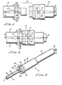
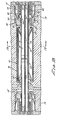
- the fiber connector may itself be advantageously included within the elements of a typical plug and receptacle connector 13, as shown in Figures 1 and 2, for example, of the kind that is more typically used for interconnecting two multi-wire electrical cables together. That is, an incoming fiber 10' mounted within a fiber contact 14' to be described is, in turn, mounted within a receptacle 15 of the conventional plug and receptacle connector 13. Similarly, another fiber 10 is mounted within a fiber contact 14 identical to contact 14' and which includes an alignment sleeve 16 to be described. The fiber 10, fiber contat 14 and alignment sleeve 16 are mounted with the connector plug 17.
- the plug and receptacle 17 and 15 are joined in the conventional manner which causes the end parts of the optical fibers carried by contacts 14 and 14' to be received within the alignment sleeve 16 and thus properly orienting the optical fibers 10 and 10' as depicted in Figure 2.
- the plug and receptacle 17 and 15 are merely released from each other in the usual manner.
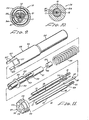
- Three alignment pins 18 are provided for each holder with each being seen to include a cylindrical shaft portion 19 of uniform diameter, a smaller diameter portion 20 and an end portion having a plurality of mutually spaced, raised circular ridges 21 with relatively sharp outer edges.
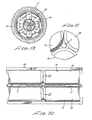
- the diameter of the raised ridges is slightly less than that of the uniform portion 19 so that the three pins for each holder can be brought together with their circumferential peripheries of the portions 19 in mutual contacting relation as shown in Figure 19.
- the contact housing 22 ( Figure 11) is an elongated, one-piece, hollow tubular member, approximately one-half thereof being of a relatively large outer diameter as at 23 and the other half 24 being of a smaller outer diameter.
- the housing part 23 includes a relatively large diameter circular bore 25 which is in communication with a smaller diameter bore 26 in the contact housing 14.
- four rectangular slots 27 are formed in the outer end of the large diameter part 23 at 90 degree intervals.
- An elongated hollow ferrule 28 has a triangular cross-section end portion 29 which tapers sharply as at 30 into a cylindrical end portion 31.
- a dislike location flange 32 is disposed on the triangular portion 29 spaced inwardly from its outer end.
- a central extent of the triangular part 29 (indicated by dashed lines) are formed or crimped inwardly for a reason and purpose to be described.
- the internal dimensions of the bore of the triangular part 29 are such that they can receive the three positioning pins 18 in the respective corners with the raised ridges 21 lying at the inner end of the triangular portion abutting against a shoulder 33 and defining the transition from the triangular bore to the circular bore 31.
- a coil spring 34 has an outer diameter enabling it to be fittingly received within the housing opening 25 and an internal diameter such that it can be received over the sleeve 29 and abut against the location plate 32 ( Figure 11).
- the unstressed spring length substantially equals that of the bore 25 measured to a point about midway of the slots 27.
- An axial opening 36 of the grommet is of such dimensions as to accommodate fittingly an optical fiber with insulative or protective covering 12 ( Figure 17).
- An end cap 37 has portions which fit into the slots 27 at the end of the housing 22 and has other intervening parts fitting over the housing end portions such that the cap can be slipped onto the housind end and retained there for a purpose to be described. It also includes an axial opening 38 passing therethrough.
- the end cap 37 is a one-piece, generally disklike member having an axial opeing 38 of dimensions as to enable the three pins 18 and included fiber 11 to extend unimpeded therethrough.
- Four slots 39 are arranged at 90 degree angular circumferential spacing and extend longitudinally along the sides and across the outer face of the cap.
- an optical fiber 10 the end of which is to be interconnected with another fiber is passed through the contact housing 22 and then through the spring 34.
- the fiber receives the grommet 35 followed by the ferrule 28.
- an end portion of the fiber is stripped of its protective covering leaving the fiber bare of a length equal to that of the uniform diametral part 19 of an alignment pin plug part of the small diametral portion 20.
- the three alignment pins 18 are introduced through the opening near the flange 32 ( Figure 11) and arranged about the fiber with the raised ridges 21 being located at the innermost end of the triangular housing and contacting the fiber insulation 12.
- the triangular portion 29 of the ferrule 28 positions the three pins 18 at 120 degrees with respect to each other, and the uniform diameter portion 19 of each engages the bare fiber periphery.
- the pins and included fiber are inserted through the cap opening 38 and the faced-off end of the fiber is located inwardly of the outer ends of the three containing pins by a fixture (not shown).
- the ends of the pins 18 are chamfered at about 45°.
- the fixture has a first abutment surface which locates against the plane of the end faces of pins 18 and a second abutment surface raised forwardly by a predetermined increment.
- the second face of the fixture engages the end face of the fiber within the space enclosed by the chamfered faces of the pins and presses it slightly rearwadly of the plane of the end faces of pins 18 but forwardly of the plane defining the rearward extremeties of the chamfered faces.
- the ferrule is then adjusted in position and crimped about the pins whereby the pins are fixedly secured within the ferrule 28 at 120 degrees with respect to each other and the fiber is firmly positioned along the common passageway between the alignment pins.
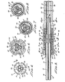
- the ferrule 28 with included pins and fiber are slidingly located within the slotted end of the housing 22 until they assume the position shown in Figure 5.
- the tines 27' are then peened over to secure the end cap in place.
- the three pins 18 including the bare fiber are of such total width dimensions as to permit their passing through cap opening 38 with only slight spacing from cap opening walls (Figure 6).
- the ferrule triangular portion 29 fits closely about the three pins continuously contacting approximately one-half the outer peripheral surface of each pin ( Figure 7).
- the second fiber or fiber part 10' is mounted in a further contact 14' which is identical to the holder 14. For that reason, no description will be given of the holder 14' construction.
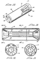
- the housing 41 includes a thin-wall metal cylindrical tube with the circular ends bent radially inwardly and back towards the opposite end a slight amount. That is, each end of the sleeve terminates in a continous circular concave shoulder 43 which faces inwardly of the sleeve toward the opposite end.
- the internal dimensions of the sleeve (diameter and length) have a specific relation to the alignment means that will be described.
- the alignment means or sleeve spring 42 is shown there in flat-sheet form as it is initially made. That is, the resilient means consists of a rectangular sheet of spring metal having a plurality of equally spaced slots 44 extending parallel to each other from one edge of the sheet. A further set of slots 45 extend from the opposite end to lie midway between the slots 44. The end portions are then bent about the axes 46 and 47 in the same direction.
- the resilient means are formed into a tubular shape with lateral edges abutting and then slid into the housing 41 with the radially outwardly splayed end portions being anchored behind the shoulders 43 as shown in Figure 13, for example.
- the central space of the resilients means has a cross- sectional dimension b ( Figure 14) enabling resilient receipt and retention of the two sets of pins and included fibers extending from contacts 14 and 14'.
- a decided advantage of this invention is that due to its relative simplicity, fiber interconnections can be accomplished under field conditions. More particularly, as shown in Figure 22 a complete set of equipment for achieving the various assembly steps for this invention may be carried in one portable enclosure.
- a stripping means 48 having spaced facing cutting surfaces removes the fiber cladding in much the same way that insulation is removed from an electric wire.
- a cutting tool 49 operable by a hand lever 50 cleaves the fiber leaving an end face closely approximating 90 degrees.
- Special fixtures 51 and 52 hold the fiber and connector parts while the contact is assembled and the ferrule clamped into place, respectively.
- the optical fiber connector described herein can be readily incorporated into a conventional electrical cable plug and receptacle connector ( Figures 1 and 2). Also, although only one fiber connector is depicted in Figures 1 and 2 being used in a plug and receptacle connector, it is considered to be within the spirit of this invention to provide a plurality of such fiber connectors within the same plug and receptacle shells such that a number of optical fibers may be simultaneously connected/ disconnected in accordance with this invention. Still further, the plug and connectors shells protect the optical fiber connectors from the possibility of damage, as well as reinforcing and maintaining the fiber connection.
- the described connector accomplishes reliable connection of optical fibers without the requirement for highly toleranced parts, the cost of which could be prohibitive. Also, this connector can be quickly and easily utilised under field conditions to interconnect two fibers or to repair broken or damaged fibers. Disassembly is a relatively simple matter and all of the connector parts, except perhaps the ferrule 28, can be salvaged and used again.
Landscapes
- Physics & Mathematics (AREA)
- General Physics & Mathematics (AREA)
- Optics & Photonics (AREA)
- Mechanical Coupling Of Light Guides (AREA)
Applications Claiming Priority (2)
| Application Number | Priority Date | Filing Date | Title |
|---|---|---|---|
| US06/306,330 US4483584A (en) | 1981-09-28 | 1981-09-28 | Optical fiber connector |
| US306330 | 1989-02-03 |
Publications (2)
| Publication Number | Publication Date |
|---|---|
| EP0076053A2 true EP0076053A2 (de) | 1983-04-06 |
| EP0076053A3 EP0076053A3 (de) | 1983-06-29 |
Family
ID=23184812
Family Applications (1)
| Application Number | Title | Priority Date | Filing Date |
|---|---|---|---|
| EP82304755A Ceased EP0076053A3 (de) | 1981-09-28 | 1982-09-09 | Verbindungsstück für optische Fasern |
Country Status (7)
| Country | Link |
|---|---|
| US (1) | US4483584A (de) |
| EP (1) | EP0076053A3 (de) |
| JP (1) | JPS5863909A (de) |
| AU (1) | AU8493082A (de) |
| BR (1) | BR8204024A (de) |
| CA (1) | CA1208056A (de) |
| IL (1) | IL66058A0 (de) |
Cited By (4)
| Publication number | Priority date | Publication date | Assignee | Title |
|---|---|---|---|---|
| EP0227270A1 (de) * | 1985-11-12 | 1987-07-01 | G & H Technology, Inc. | Vorrichtung zum Trennen von Lichtleitfasern |
| EP0159768A3 (de) * | 1984-04-09 | 1988-01-13 | G & H Technology, Inc. | Gerät zur Pressung einer optischen Faser |
| EP0373340A1 (de) * | 1988-12-16 | 1990-06-20 | Quante Ag | Lösbare Steckverbindung zum Koppeln von zwei Lichtwellen-Leitern |
| WO2013122865A1 (en) * | 2012-02-16 | 2013-08-22 | Tyco Electronics Corporation | Multi- channel optical connector with inserts |
Families Citing this family (21)
| Publication number | Priority date | Publication date | Assignee | Title |
|---|---|---|---|---|
| US4687291A (en) * | 1984-06-08 | 1987-08-18 | Amp Incorporated | Duplex electro-fiber connector assembly |
| US4712860A (en) * | 1985-07-15 | 1987-12-15 | Itt Corporation | Retrofittable optic fiber contact assembly |
| US4744629A (en) * | 1985-08-16 | 1988-05-17 | Augat Inc. | Multifiber optical cable connector |
| SE467712B (sv) * | 1989-10-13 | 1992-08-31 | Anders Nodfelt | Foerbindelseanordning foer optiska fibrer med koniska centreringsorgan |
| US5220630A (en) * | 1992-05-12 | 1993-06-15 | At&T Bell Laboratories | Optical fiber three-rod connector having a rod-securing clip |
| US5949938A (en) * | 1996-11-15 | 1999-09-07 | Pk Technology, Inc. | Aligner for slender elongate members |
| JP2000081541A (ja) * | 1998-06-29 | 2000-03-21 | Yazaki Corp | 光ファイバコネクタ |
| CA2397280A1 (en) * | 2002-08-09 | 2004-02-09 | Le Savoir Du Gardien Inc. | Optical fiber connector assembly |
| US7165892B2 (en) * | 2003-10-07 | 2007-01-23 | Halliburton Energy Services, Inc. | Downhole fiber optic wet connect and gravel pack completion |
| US7228898B2 (en) * | 2003-10-07 | 2007-06-12 | Halliburton Energy Services, Inc. | Gravel pack completion with fluid loss control fiber optic wet connect |
| US7191832B2 (en) * | 2003-10-07 | 2007-03-20 | Halliburton Energy Services, Inc. | Gravel pack completion with fiber optic monitoring |
| CA2446533A1 (en) * | 2003-10-24 | 2005-04-24 | 9134-9001 Quebec Inc. | Flexible ferrule device for connection of optical fiber and use thereof |
| US7210856B2 (en) | 2004-03-02 | 2007-05-01 | Welldynamics, Inc. | Distributed temperature sensing in deep water subsea tree completions |
| US7252437B2 (en) * | 2004-04-20 | 2007-08-07 | Halliburton Energy Services, Inc. | Fiber optic wet connector acceleration protection and tolerance compliance |
| US7641395B2 (en) * | 2004-06-22 | 2010-01-05 | Halliburton Energy Serives, Inc. | Fiber optic splice housing and integral dry mate connector system |
| US7594763B2 (en) * | 2005-01-19 | 2009-09-29 | Halliburton Energy Services, Inc. | Fiber optic delivery system and side pocket mandrel removal system |
| EP2363739A3 (de) * | 2006-06-21 | 2011-09-21 | Firecomms Limited | Optischer Stecker |
| JP2014126655A (ja) * | 2012-12-26 | 2014-07-07 | Yazaki Corp | 光コネクタ装置 |
| US9410380B2 (en) * | 2013-05-02 | 2016-08-09 | Baker Hughes Incorporated | Systems and methods for providing fiber optics in downhole equipment |
| DE102013020552A1 (de) * | 2013-12-12 | 2015-06-18 | Daimler Ag | Faserbündelanordnung sowie Verfahren zum Herstellen einer solchen Faserbündelanordnung |
| CN119960119B (zh) * | 2024-10-24 | 2025-11-28 | 图湃(北京)医疗科技有限公司 | 一种光纤连接结构及超乳玻切机 |
Family Cites Families (14)
| Publication number | Priority date | Publication date | Assignee | Title |
|---|---|---|---|---|
| JPS5225648A (en) * | 1975-08-22 | 1977-02-25 | Nippon Telegr & Teleph Corp <Ntt> | Ends of optical fibers |
| US4047796A (en) * | 1975-09-15 | 1977-09-13 | International Telephone And Telegraph Corporation | Precision optical fiber connector |
| JPS5277735A (en) * | 1975-12-24 | 1977-06-30 | Nippon Telegr & Teleph Corp <Ntt> | Optical cable connector plug |
| FR2344853A1 (fr) * | 1976-02-27 | 1977-10-14 | Thomson Csf | Fiche d'interconnexion de cables a fibres optiques |
| US4056305A (en) * | 1976-04-26 | 1977-11-01 | International Telephone And Telegraph Corporation | Single optical fiber connector utilizing elastomeric alignment device |
| JPS52138950A (en) * | 1976-05-17 | 1977-11-19 | Nippon Telegr & Teleph Corp <Ntt> | Connector plug for optical-fibre |
| FR2370294A2 (fr) * | 1976-11-09 | 1978-06-02 | Comp Generale Electricite | Dispositif de positionnement de fibre |
| US4099832A (en) * | 1976-12-27 | 1978-07-11 | Bell Telephone Laboratories, Incorporated | Optical fiber connector utilizing nested rod arrangement |
| US4123139A (en) * | 1976-12-27 | 1978-10-31 | Bell Telephone Laboratories, Incorporated | Optical fiber connector |
| US4087155A (en) * | 1977-03-23 | 1978-05-02 | International Telephone & Telegraph Corporation | Single optical fiber connector utilizing spherical alignment elements |
| GB1558914A (en) * | 1977-04-14 | 1980-01-09 | Standard Telephones Cables Ltd | Fibre optic connectors |
| FR2403571A1 (fr) * | 1977-09-14 | 1979-04-13 | Cables De Lyon Geoffroy Delore | Dispositif mecanique de raccordement de fibres optiques |
| FR2469725A1 (fr) * | 1979-11-08 | 1981-05-22 | Lyonnaise Transmiss Optiques | Connecteur pour fibres optiques |
| US4370022A (en) * | 1980-08-01 | 1983-01-25 | Amp Incorporated | Biconical optical waveguide splice |
-
1981
- 1981-09-28 US US06/306,330 patent/US4483584A/en not_active Expired - Lifetime
-
1982
- 1982-06-14 IL IL66058A patent/IL66058A0/xx unknown
- 1982-06-16 AU AU84930/82A patent/AU8493082A/en not_active Abandoned
- 1982-07-12 BR BR8204024A patent/BR8204024A/pt unknown
- 1982-08-03 JP JP57135626A patent/JPS5863909A/ja active Pending
- 1982-09-09 EP EP82304755A patent/EP0076053A3/de not_active Ceased
- 1982-09-27 CA CA000412261A patent/CA1208056A/en not_active Expired
Cited By (7)
| Publication number | Priority date | Publication date | Assignee | Title |
|---|---|---|---|---|
| EP0159768A3 (de) * | 1984-04-09 | 1988-01-13 | G & H Technology, Inc. | Gerät zur Pressung einer optischen Faser |
| EP0227270A1 (de) * | 1985-11-12 | 1987-07-01 | G & H Technology, Inc. | Vorrichtung zum Trennen von Lichtleitfasern |
| EP0373340A1 (de) * | 1988-12-16 | 1990-06-20 | Quante Ag | Lösbare Steckverbindung zum Koppeln von zwei Lichtwellen-Leitern |
| WO2013122865A1 (en) * | 2012-02-16 | 2013-08-22 | Tyco Electronics Corporation | Multi- channel optical connector with inserts |
| CN104094145A (zh) * | 2012-02-16 | 2014-10-08 | 泰科电子公司 | 具有插件的多通道光学连接器 |
| CN104094145B (zh) * | 2012-02-16 | 2017-08-15 | 泰科电子公司 | 具有插件的多通道光学连接器 |
| US10302876B2 (en) | 2012-02-16 | 2019-05-28 | Te Connectivity Corporation | Multi-channel optical insert |
Also Published As
| Publication number | Publication date |
|---|---|
| IL66058A0 (en) | 1982-09-30 |
| JPS5863909A (ja) | 1983-04-16 |
| EP0076053A3 (de) | 1983-06-29 |
| AU8493082A (en) | 1983-04-14 |
| US4483584A (en) | 1984-11-20 |
| CA1208056A (en) | 1986-07-22 |
| BR8204024A (pt) | 1983-12-20 |
Similar Documents
| Publication | Publication Date | Title |
|---|---|---|
| US4483584A (en) | Optical fiber connector | |
| US4854664A (en) | Multi-fiber optic cable connector and cable apparatus | |
| US3963323A (en) | Fiber optic connector with protective cable sleeves | |
| US9274286B2 (en) | Reversible fiber optic stub clamping mechanism | |
| US5450517A (en) | Re-enterable fiber optic splicer for data communications | |
| US4127319A (en) | Termination means for fiber optic bundle | |
| US5867620A (en) | Fixture for fabricating a fiber optic connector ferrule | |
| US4684205A (en) | Fiber optic connector with compensating mechanism | |
| US5923803A (en) | Method of fabricating a fiber optic connector ferrule | |
| US4201444A (en) | Single optical fiber connector | |
| US4208092A (en) | Fiber optic multi-cable pair connector | |
| EP0209759A2 (de) | Stecker für optische Faser | |
| CA1177234A (en) | Device for positioning optical fibers in a terminal connector for splicing two optical-fiber transmission cables | |
| CA1247419A (en) | Optical fiber connector | |
| US4643520A (en) | Method of terminating fiber optic connector without polishing optical fiber | |
| US4605281A (en) | Self-aligning fiber optic connector | |
| US4205897A (en) | Fiber optic connector for single fiber | |
| US4707068A (en) | Optical fiber waveguide connector system | |
| US4850664A (en) | Connector for optical fiber | |
| JP2001281494A (ja) | 光コネクタフェルールの製造方法 | |
| US5963691A (en) | Alignment system in a connector ferrule for a fiber optic cable | |
| EP0896235A1 (de) | Steckerstift für einen faseroptischen Stecker | |
| JPS6037527Y2 (ja) | 光フアイバ伝送路用コネクタ | |
| US5216736A (en) | Welded splice element | |
| EP0095281A2 (de) | Verbindungsglied für ein faseroptisches Bauteil |
Legal Events
| Date | Code | Title | Description |
|---|---|---|---|
| PUAI | Public reference made under article 153(3) epc to a published international application that has entered the european phase |
Free format text: ORIGINAL CODE: 0009012 |
|
| AK | Designated contracting states |
Designated state(s): BE CH DE FR GB IT LI LU NL SE |
|
| PUAL | Search report despatched |
Free format text: ORIGINAL CODE: 0009013 |
|
| AK | Designated contracting states |
Designated state(s): BE CH DE FR GB IT LI LU NL SE |
|
| 17P | Request for examination filed |
Effective date: 19831216 |
|
| STAA | Information on the status of an ep patent application or granted ep patent |
Free format text: STATUS: THE APPLICATION HAS BEEN REFUSED |
|
| 18R | Application refused |
Effective date: 19851114 |
|
| RIN1 | Information on inventor provided before grant (corrected) |
Inventor name: GRESTY, JOHN B. |