EP0076063A2 - Dispositif de connexion électrique - Google Patents
Dispositif de connexion électrique Download PDFInfo
- Publication number
- EP0076063A2 EP0076063A2 EP82304877A EP82304877A EP0076063A2 EP 0076063 A2 EP0076063 A2 EP 0076063A2 EP 82304877 A EP82304877 A EP 82304877A EP 82304877 A EP82304877 A EP 82304877A EP 0076063 A2 EP0076063 A2 EP 0076063A2
- Authority
- EP
- European Patent Office
- Prior art keywords
- electrical connection
- switching means
- component
- pin
- contact member
- Prior art date
- Legal status (The legal status is an assumption and is not a legal conclusion. Google has not performed a legal analysis and makes no representation as to the accuracy of the status listed.)
- Granted
Links
Images


Classifications
-
- H—ELECTRICITY
- H01—ELECTRIC ELEMENTS
- H01R—ELECTRICALLY-CONDUCTIVE CONNECTIONS; STRUCTURAL ASSOCIATIONS OF A PLURALITY OF MUTUALLY-INSULATED ELECTRICAL CONNECTING ELEMENTS; COUPLING DEVICES; CURRENT COLLECTORS
- H01R13/00—Details of coupling devices of the kinds covered by groups H01R12/70 or H01R24/00 - H01R33/00
- H01R13/66—Structural association with built-in electrical component
- H01R13/70—Structural association with built-in electrical component with built-in switch
- H01R13/71—Contact members of coupling parts operating as switch, e.g. linear or rotational movement required after mechanical engagement of coupling part to establish electrical connection
Definitions
- This invention relates to electrical connection devices for connecting electrical appliances to an electric current supply and includes within its scope electrical switches including switch bodies and switch plates, extension cords, connection plugs, connection socket bodies and the like.
- the invention is primarily concerned with the outwardly extending connection pins or terminals attached to one device and to the corresponding recesses which contain or are associated with contacting terminals for said outwardly extending pins or terminals.
- Australian specification 13981/76 in the name of D .J. Rohrssen discloses an electrical correction device including a male body having the aforementioned outwardly extending connection pins and a female body having the aforementioned recesses.
- the male body or plug has an outer planar face from which the connection pins extend and the female body or socket body also has a planar face containing the above mentioned recesses and wherein the respective faces of both plug and socket body may abut when attached together.
- connection pins in the above mentioned Rohrssen specification are provided with laterally offset portions which are located at the respective free ends of the shank of each pin.
- the recesses for each of these pins includes an arcuate portion and a laterally offset portion and are complementary in shape to their associated conducting pins of the plug.
- the plug also has a central earthing pin which engages in a mating cylindrical recess or passage in the socket body. The arrangement is such that as the pins of the plug are inserted in their mating recesses it requires a pivotal or rotational motion of the plug relative to the socket body to bring about complete engagement and thereby electrically connect the connection pins of the plugs to their associated contact terminals located in the respective recesses of the socket body. In this procedure the central earthing pin of the plug may serve as a pivot pin about which the connection pins may be pivoted or rotated.
- an electrical connection device including:
- the male component is suitably connectable to an electrical appliance such as a toaster, refrigerator, electrical light fitting, electric shaver and the like and is suitably a connection plug having a planar face from which said plurality of connection pins extend preferably at right angles thereto.
- the female component is suitably attachable to a source of electrical supply through said connection terminals which are suitably located in a base portion thereof.
- the female component includes a front planar face which accommodates said plurality of recesses.
- the female component may include a switch body or switch plate or a socket body which engages with the connection plug referred to above.
- the socket body may be part of an extension cord or other electrical connection component.
- connection pins of the male component are suitably conducting pins of any suitable shape and which are preferably arcuate or curved. There may be located at each free or outer end of each conducting pin a laterally extending portion which if offset relative to the longitudinal axis of the conducting pin.
- the recess of the female component are appropriately similar in shape to their respective mating conducting pins and may be provided at their respective inner ends with a laterally extending or offset inner end portion which is complementary or similar in shape to the offset outer end portion of each conducting pin.
- a centrally located guide pin or earthing pin of the male component which is preferably longer than the pair of conducting pins (i.e. neutral and active).
- the guide pin may act as a fulcrum or pivot point when the male component is rotated relative to the female component before the above described offset outer end portions of the conducting pins engage in their respective laterally extending or offset inner end portions of their mating recesses.
- contact members which are suitably located in or associated with the offset inner end portions of the recesses in the female component and which extend downwardly from said recesses torwards the base portion of the female component.
- the switching means in one form may include a switching arm rotatably attached to the female component and having a centrally located aperture which is engaged by the above described central guide pin when the male component is rotated relative to the female component. This in turn causes rotation or pivotal movement of the switching arm so as to effect electrical connection between each contact member and an associated connection terminal.
- each of the contact members at their lower or downwardly extending ends have attached thereto a rocker arm pivotally attached to the contact member which engages with an adjacent portion of the switching arm whereby upon movement of the switching arm in one direction each rocker arm may pivot from a position of disengagement with an associated connection terminal to an engagement position. Movement of the switching arm in the other or opposite direction may cause movement of each rocker arm back to the disengaged position.
- each rocker arm is biassed by suitable biasing means towards the disengaged position.
- each end of the switching arm may act as a bridge between each contact member and an adjacent connection terminal when the switching arm is rotated in one direction and.when rotated in the opposite direction each end of the switching arm may firmly engage with the contact member in a snap fit or clipped relationship so as to constrain or firmly retain the switching arm in the disengaged position or non bridging position.
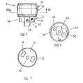
- female component 10 having a planar front face ll,curved recesses 12 and cylindrical recess or passage 13.
- Recesses 12 have laterally offset end portions 14 which are located adjacent contact members 15 having a shank or stem 16 to which is attached pivot pin or part 17 for rocker arm 18.
- supply terminals 19 and switching arm 20 rotationally supported in a cavity 19A within female component 10.
- Each end of switching arm 20 is supported by spring loaded balls 22 biased by springs 23 which urge the arm 20 towards the position shown in FIG 9 or the position in dotted outline.
- Switching arm 20 has central aperture 21 and has a bulbous or spherical middle part 23A which is retained in position by bearing surfaces 24 of female component 10.
- rocker arms 18 may pivot about their respective pivot pins 17 and one end of rocker arm 20 may engage with an adjacent terminal 19 as shown in the dotted outline. Movement of rocker arms 1e is caused by movement of balls 22 which are moved upon rotational movement of switching arm 20.
- Supply terminals 19 may form part of a terminal body 19B which can engage with conducting cables (not shown) by the use of clamping screws 25. There is also shown an earthing terminal 26 which may engage with an earth wire (not shown) by clamping screw 27.
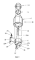
- the female component may be formed by top part A, intermediate body part B, plate C and terminal part D as shown in FIG 1.
- Place C has central aperture 21A for the guide pin of the male component.
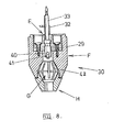
- Plug or male component 30 includes a pair of conducting pins 32 having laterally offset end portions 32A. There is also shown centrally located guide pin or earthing pin 33 having a cross sectional shape complementary to recess 21 of switching arm 20.
- Plug 30 has planar face 34 which abuts with mating face 11 of female component 10 when engaged with female component 10.
- Guide pin 33 has terminal 33A for engaging with terminal 26 previously described.
- pins 32 locate in recesses 35 of component 30.
- Component 30 also comprises body portion E, housing component F, cord retaining means G and guide component H. Attachment screws36 having covers 37 attach component E to component F through sockets 37A.
- FIG 9 there is shown a modified switching arm 20A having central aperture 21A and having a ball shaped central portion supported by bearing surfaces 24A of female component 10.
- Switching arm 20A is shown in the operative position forming a bridge between supply terminals 19 and contact members 16A.
- resilient ends 38 of contact members 16A engage with mating surfaces 39 of switching arm 2CA, Switching arm 20A also has contact surface 41 which engages with supply terminals 19 as shown.
- each end of switching arm 20A bear against an associated contact member 16A.
- each end of switching arm 20A is retained firmly in the inoperative position unless rotated clockwise by guide pin 33 engaging in central aperture 21A.
- Guide pin 33 of male component 30 also has aperture 40 for retention of an earthing wire (not shown) which retained therein by screws4l.
- Cord retaining device G has elongate slots 42 which have a self-tightening action about an electrical cord (not shown) when the various parts of male component 30 are assembled together.
- Cord retaining device G is resiliently deformable.
- Conducting pins 32 of plug or male component 30 engage in curved recesses 12 of female component 10 so that laterally offset ends 32A may engage in offset inner ends 14 of recesses 12, and thereby engage with contact members 15 or 16A.
- guide pin 33 engages in central aperture 21 or 21A of switching arm 20 or 20A and causes rotation of switching arm 20 or 20A to cause electrical connection between pins 32 and supply terminals 19 as described above. This provides positive protection against electrocution if a conductor is inadvertantly inserted in recesses 12 because of the fact that although contact member 15 or 16A may be contacted there is still no electrical connection between contact member 16A and supply terminal 19. This requires rotation of switching arm 20 or 20A.
- recesses 12 are located on the circumference of a common circle as shown in FIG 7 relative to face 11 as is the case with conducting pins 32 relative to face 34. Laterally offset portions 32A of pins 32 also follow the circumference of the same common circle as shown in FIG 4. The same applies to laterally offset inner-ends 14 of the recesses 12.
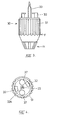
- Female component or socket 10 includes attachment projection 45 for the earth wire 46 for the neutral wire and 47 for the active wire. Each projection has associated passages 48, 49 and 50 for retention of their respective wires which are secured by screws 25 and 27.
- Male component 30 may be milled or provided with corrugations 51 as shown in FIGS 3-4 which may act as a suitable finger grip.
- the leading end 33A of pin 33 may be inserted into recess 13 and pins 32 alinged with mating recesses 12 by rotation of male component 30 clockwise relative to female component 10. Then components 10 and 30 may be engaged so that faces 11 and 34 are in mutual abutting relationship. Then male component 30 may be rotated 45 which will then place faces 11 and 34 in full engagement with the switching arm 20 or 20A being rotated to the operative position by guide pin 33. Disconnection may be achieved by an anti-clockwise turn of male component 30 relative to female component 10.
- the invention includes within its scope the male component per se.and the female component per se.
- central pin 33 actuating movement of switching arm 20 or 20A as previously described
- other appropriate actuating means for actuating movement of switching arm 20 or 20A may be utilized.
- movement of the switching arm 20 or 20A may be actuated by one or both connection pins 32 of male component or plug 30.
Landscapes
- Details Of Connecting Devices For Male And Female Coupling (AREA)
Priority Applications (1)
| Application Number | Priority Date | Filing Date | Title |
|---|---|---|---|
| AT82304877T ATE26898T1 (de) | 1981-09-24 | 1982-09-16 | Elektrische verbindungsanordnung. |
Applications Claiming Priority (2)
| Application Number | Priority Date | Filing Date | Title |
|---|---|---|---|
| AU906/81 | 1981-09-24 | ||
| AUPF090681 | 1981-09-24 |
Publications (3)
| Publication Number | Publication Date |
|---|---|
| EP0076063A2 true EP0076063A2 (fr) | 1983-04-06 |
| EP0076063A3 EP0076063A3 (en) | 1985-01-02 |
| EP0076063B1 EP0076063B1 (fr) | 1987-04-29 |
Family
ID=3769217
Family Applications (1)
| Application Number | Title | Priority Date | Filing Date |
|---|---|---|---|
| EP82304877A Expired EP0076063B1 (fr) | 1981-09-24 | 1982-09-16 | Dispositif de connexion électrique |
Country Status (16)
| Country | Link |
|---|---|
| US (1) | US4520243A (fr) |
| EP (1) | EP0076063B1 (fr) |
| JP (1) | JPS5866273A (fr) |
| KR (1) | KR840001784A (fr) |
| AR (1) | AR229825A1 (fr) |
| AT (1) | ATE26898T1 (fr) |
| BR (1) | BR8205583A (fr) |
| CA (1) | CA1229362A (fr) |
| DE (1) | DE3276208D1 (fr) |
| FI (1) | FI71445C (fr) |
| IL (1) | IL66855A0 (fr) |
| IN (1) | IN157972B (fr) |
| MX (1) | MX152848A (fr) |
| NZ (1) | NZ201877A (fr) |
| PH (1) | PH19669A (fr) |
| ZA (1) | ZA826689B (fr) |
Cited By (3)
| Publication number | Priority date | Publication date | Assignee | Title |
|---|---|---|---|---|
| EP0420377A3 (en) * | 1989-09-25 | 1991-07-17 | Lucerne Products, Inc. | Electrical adapter for interconnection with a switch |
| US5336103A (en) * | 1993-08-26 | 1994-08-09 | Herboldsheimer John D | Female socket-based male plug locking device |
| US6328597B1 (en) | 2000-04-05 | 2001-12-11 | Oliver W. Epps | Electrical power and disabling jack |
Families Citing this family (23)
| Publication number | Priority date | Publication date | Assignee | Title |
|---|---|---|---|---|
| DE3471408D1 (en) * | 1984-12-27 | 1988-06-23 | Marechal Sepm | Receptacle, especially for power currents |
| US4656323A (en) * | 1985-05-13 | 1987-04-07 | Bell Industries, Inc. | Push button electric switch |
| US4772215A (en) * | 1987-10-15 | 1988-09-20 | Hubbell Incorporated | Electrical connector with enclosed internal switch |
| US4835657A (en) * | 1987-12-10 | 1989-05-30 | Parkhomenko Alexandr I | Explosion-proof electrical unit |
| US4873936A (en) * | 1988-10-31 | 1989-10-17 | Ponticelli Robert J | Switching mechanism for anti-theft system |
| JPH03125429U (fr) * | 1990-04-01 | 1991-12-18 | ||
| RU2125329C1 (ru) * | 1996-05-24 | 1999-01-20 | Частный индивидуальный исследовательский производственно-торговый центр Петрова "Сфера" | Розетка |
| US5746612A (en) * | 1996-11-13 | 1998-05-05 | Chien-Yuan; Wang | Adapter junction box |
| US6332794B1 (en) * | 2000-05-03 | 2001-12-25 | Nian Mei Tzeng Jeng | Swivellable receptacle |
| US7091124B2 (en) | 2003-11-13 | 2006-08-15 | Micron Technology, Inc. | Methods for forming vias in microelectronic devices, and methods for packaging microelectronic devices |
| US7232754B2 (en) | 2004-06-29 | 2007-06-19 | Micron Technology, Inc. | Microelectronic devices and methods for forming interconnects in microelectronic devices |
| US7425499B2 (en) | 2004-08-24 | 2008-09-16 | Micron Technology, Inc. | Methods for forming interconnects in vias and microelectronic workpieces including such interconnects |
| US7271482B2 (en) | 2004-12-30 | 2007-09-18 | Micron Technology, Inc. | Methods for forming interconnects in microelectronic workpieces and microelectronic workpieces formed using such methods |
| US7622377B2 (en) | 2005-09-01 | 2009-11-24 | Micron Technology, Inc. | Microfeature workpiece substrates having through-substrate vias, and associated methods of formation |
| US7249976B1 (en) * | 2006-03-30 | 2007-07-31 | Watson H Scott | Electrical plug, receptacle and switch |
| US7629249B2 (en) | 2006-08-28 | 2009-12-08 | Micron Technology, Inc. | Microfeature workpieces having conductive interconnect structures formed by chemically reactive processes, and associated systems and methods |
| RU2321927C1 (ru) * | 2006-12-25 | 2008-04-10 | Сергей Александрович Громазин | Предохранительная шторка для исключения доступа к контактам розетки и штепсельная розетка с этой шторкой |
| US7775813B1 (en) * | 2009-05-21 | 2010-08-17 | Yaakov Filiba | Electrical outlet with lateral connection |
| JP5602642B2 (ja) * | 2011-01-04 | 2014-10-08 | 富士通コンポーネント株式会社 | コネクタ |
| CN102412490B (zh) * | 2011-12-29 | 2014-01-29 | 苏州升德精密电气有限公司 | 一种二段旋转式插座 |
| SE540945C2 (sv) * | 2016-06-21 | 2019-01-02 | Roland Johansson | Eluttag med petskydd |
| FR3076955B1 (fr) * | 2018-01-12 | 2020-01-31 | Marechal Electric | Socle de prise equipe d'un disque et d'un obturateur |
| USD953739S1 (en) * | 2019-09-13 | 2022-06-07 | Apple Inc. | Case |
Family Cites Families (12)
| Publication number | Priority date | Publication date | Assignee | Title |
|---|---|---|---|---|
| US179313A (en) * | 1876-06-27 | Improvement in fruit-driers | ||
| FR528887A (fr) * | 1919-12-03 | 1921-11-19 | Edwin Jones | Perfectionnements aux fiches et prises de courant pour l'appareillage électrique |
| US1700437A (en) * | 1925-12-30 | 1929-01-29 | Louie E Hubbell | Locking plug switch |
| US2127473A (en) * | 1934-02-20 | 1938-08-16 | Sacco James | Electric connecter |
| US2288376A (en) * | 1939-11-22 | 1942-06-30 | Gen Electric | Lamp holder |
| US2374032A (en) * | 1944-02-14 | 1945-04-17 | Gen Electric | Lamp holder |
| US2857570A (en) * | 1956-03-06 | 1958-10-21 | American Gage & Mach | Multi-range electrical test instrument |
| FR1448243A (fr) * | 1965-06-23 | 1966-08-05 | Perfectionnements apportés aux appareils électriques du genre des interrupteurs etinverseurs de courant | |
| JPS5228795U (fr) * | 1975-08-21 | 1977-02-28 | ||
| US4148536A (en) * | 1976-11-22 | 1979-04-10 | Petropoulsos Nikolaostzakos J | Safety electrical receptacle |
| GB2025156B (en) * | 1978-07-10 | 1982-10-27 | Playsafe Electrics | Electrical plug and sockets |
| US4185881A (en) * | 1978-07-19 | 1980-01-29 | Playsafe Electrics Proprietary Limited | Electrical plug and socket arrangement |
-
1982
- 1982-09-10 NZ NZ201877A patent/NZ201877A/en unknown
- 1982-09-10 US US06/416,762 patent/US4520243A/en not_active Expired - Lifetime
- 1982-09-13 FI FI823158A patent/FI71445C/fi not_active IP Right Cessation
- 1982-09-13 AR AR290632A patent/AR229825A1/es active
- 1982-09-13 ZA ZA826689A patent/ZA826689B/xx unknown
- 1982-09-15 PH PH27878A patent/PH19669A/en unknown
- 1982-09-15 CA CA000411444A patent/CA1229362A/fr not_active Expired
- 1982-09-16 EP EP82304877A patent/EP0076063B1/fr not_active Expired
- 1982-09-16 IN IN1070/CAL/82A patent/IN157972B/en unknown
- 1982-09-16 DE DE8282304877T patent/DE3276208D1/de not_active Expired
- 1982-09-16 AT AT82304877T patent/ATE26898T1/de not_active IP Right Cessation
- 1982-09-22 JP JP57167463A patent/JPS5866273A/ja active Granted
- 1982-09-23 KR KR1019820004295A patent/KR840001784A/ko not_active Ceased
- 1982-09-23 MX MX194489A patent/MX152848A/es unknown
- 1982-09-23 IL IL66855A patent/IL66855A0/xx not_active IP Right Cessation
- 1982-09-23 BR BR8205583A patent/BR8205583A/pt not_active IP Right Cessation
Cited By (3)
| Publication number | Priority date | Publication date | Assignee | Title |
|---|---|---|---|---|
| EP0420377A3 (en) * | 1989-09-25 | 1991-07-17 | Lucerne Products, Inc. | Electrical adapter for interconnection with a switch |
| US5336103A (en) * | 1993-08-26 | 1994-08-09 | Herboldsheimer John D | Female socket-based male plug locking device |
| US6328597B1 (en) | 2000-04-05 | 2001-12-11 | Oliver W. Epps | Electrical power and disabling jack |
Also Published As
| Publication number | Publication date |
|---|---|
| CA1229362A (fr) | 1987-11-17 |
| FI71445C (fi) | 1986-12-19 |
| AR229825A1 (es) | 1983-11-30 |
| NZ201877A (en) | 1985-02-28 |
| PH19669A (en) | 1986-06-09 |
| FI823158L (fi) | 1983-03-25 |
| ZA826689B (en) | 1983-07-27 |
| IL66855A0 (en) | 1982-12-31 |
| JPS6352432B2 (fr) | 1988-10-19 |
| IN157972B (fr) | 1986-08-09 |
| MX152848A (es) | 1986-06-18 |
| EP0076063B1 (fr) | 1987-04-29 |
| BR8205583A (pt) | 1983-08-30 |
| FI71445B (fi) | 1986-09-09 |
| FI823158A0 (fi) | 1982-09-13 |
| ATE26898T1 (de) | 1987-05-15 |
| DE3276208D1 (en) | 1987-06-04 |
| KR840001784A (ko) | 1984-05-16 |
| EP0076063A3 (en) | 1985-01-02 |
| US4520243A (en) | 1985-05-28 |
| JPS5866273A (ja) | 1983-04-20 |
Similar Documents
| Publication | Publication Date | Title |
|---|---|---|
| EP0076063A2 (fr) | Dispositif de connexion électrique | |
| US3980372A (en) | Electrical socket | |
| US5759051A (en) | Raceway with track mounted electrical receptacles randomly placed | |
| US5847345A (en) | Push button electrical switch | |
| KR900002498A (ko) | 전기 콘넥터 | |
| EP0363804A1 (fr) | Mécanisme de verrouillage pour connecteur électrique du type fiche et douille | |
| AU2010246500A1 (en) | A Universal Power Socket | |
| EP2011190A1 (fr) | Dispositif a prise electrique de securite | |
| US4450323A (en) | Reversible switch | |
| CN112038817A (zh) | 电插座 | |
| EP0390449A3 (fr) | Connecteur électrique | |
| US2777023A (en) | Electric lock plug | |
| US5098307A (en) | Adjustable duplex receptacle | |
| GB2126805A (en) | Electrical plug | |
| US7067745B2 (en) | Safety switch assembly | |
| US3649780A (en) | Electric reversing switch | |
| EP2133961B1 (fr) | Prise universale | |
| GB2256323A (en) | Electrical trailing socket with switches | |
| US4144429A (en) | Manually operated electrical switch | |
| GB858692A (en) | Improvements relating to electrical plug and socket connectors | |
| US2899524A (en) | smith | |
| KR100404925B1 (ko) | 회전 스위치 플러그 | |
| JPS6035159Y2 (ja) | 漏電ブレ−カ | |
| GB2153592A (en) | Electrical switches | |
| JPH0614359Y2 (ja) | レバースイッチ装置 |
Legal Events
| Date | Code | Title | Description |
|---|---|---|---|
| PUAI | Public reference made under article 153(3) epc to a published international application that has entered the european phase |
Free format text: ORIGINAL CODE: 0009012 |
|
| AK | Designated contracting states |
Designated state(s): AT BE CH DE FR GB IT LI NL SE |
|
| PUAL | Search report despatched |
Free format text: ORIGINAL CODE: 0009013 |
|
| AK | Designated contracting states |
Designated state(s): AT BE CH DE FR GB IT LI NL SE |
|
| 17P | Request for examination filed |
Effective date: 19850220 |
|
| GRAA | (expected) grant |
Free format text: ORIGINAL CODE: 0009210 |
|
| AK | Designated contracting states |
Kind code of ref document: B1 Designated state(s): AT BE CH DE FR GB IT LI NL SE |
|
| PG25 | Lapsed in a contracting state [announced via postgrant information from national office to epo] |
Ref country code: NL Effective date: 19870429 Ref country code: LI Effective date: 19870429 Ref country code: CH Effective date: 19870429 Ref country code: BE Effective date: 19870429 Ref country code: AT Effective date: 19870429 |
|
| REF | Corresponds to: |
Ref document number: 26898 Country of ref document: AT Date of ref document: 19870515 Kind code of ref document: T |
|
| PG25 | Lapsed in a contracting state [announced via postgrant information from national office to epo] |
Ref country code: SE Effective date: 19870430 |
|
| REF | Corresponds to: |
Ref document number: 3276208 Country of ref document: DE Date of ref document: 19870604 |
|
| REG | Reference to a national code |
Ref country code: CH Ref legal event code: PL |
|
| NLV1 | Nl: lapsed or annulled due to failure to fulfill the requirements of art. 29p and 29m of the patents act | ||
| EN | Fr: translation not filed | ||
| ITF | It: translation for a ep patent filed | ||
| PLBE | No opposition filed within time limit |
Free format text: ORIGINAL CODE: 0009261 |
|
| STAA | Information on the status of an ep patent application or granted ep patent |
Free format text: STATUS: NO OPPOSITION FILED WITHIN TIME LIMIT |
|
| 26N | No opposition filed | ||
| ET | Fr: translation filed | ||
| REG | Reference to a national code |
Ref country code: FR Ref legal event code: BR |
|
| PGFP | Annual fee paid to national office [announced via postgrant information from national office to epo] |
Ref country code: GB Payment date: 19950811 Year of fee payment: 14 |
|
| PGFP | Annual fee paid to national office [announced via postgrant information from national office to epo] |
Ref country code: FR Payment date: 19950816 Year of fee payment: 14 |
|
| PGFP | Annual fee paid to national office [announced via postgrant information from national office to epo] |
Ref country code: DE Payment date: 19950823 Year of fee payment: 14 |
|
| PG25 | Lapsed in a contracting state [announced via postgrant information from national office to epo] |
Ref country code: GB Effective date: 19960916 |
|
| PG25 | Lapsed in a contracting state [announced via postgrant information from national office to epo] |
Ref country code: FR Effective date: 19960930 |
|
| GBPC | Gb: european patent ceased through non-payment of renewal fee |
Effective date: 19960916 |
|
| PG25 | Lapsed in a contracting state [announced via postgrant information from national office to epo] |
Ref country code: DE Effective date: 19970603 |
|
| REG | Reference to a national code |
Ref country code: FR Ref legal event code: ST |
|
| REG | Reference to a national code |
Ref country code: FR Ref legal event code: ST |