EP0076078A2 - Caloducs - Google Patents
Caloducs Download PDFInfo
- Publication number
- EP0076078A2 EP0076078A2 EP82304955A EP82304955A EP0076078A2 EP 0076078 A2 EP0076078 A2 EP 0076078A2 EP 82304955 A EP82304955 A EP 82304955A EP 82304955 A EP82304955 A EP 82304955A EP 0076078 A2 EP0076078 A2 EP 0076078A2
- Authority
- EP
- European Patent Office
- Prior art keywords
- heat
- heat pipe
- pipe assembly
- assembly
- receiver
- Prior art date
- Legal status (The legal status is an assumption and is not a legal conclusion. Google has not performed a legal analysis and makes no representation as to the accuracy of the status listed.)
- Withdrawn
Links
Images

Classifications
-
- F—MECHANICAL ENGINEERING; LIGHTING; HEATING; WEAPONS; BLASTING
- F25—REFRIGERATION OR COOLING; COMBINED HEATING AND REFRIGERATION SYSTEMS; HEAT PUMP SYSTEMS; MANUFACTURE OR STORAGE OF ICE; LIQUEFACTION SOLIDIFICATION OF GASES
- F25B—REFRIGERATION MACHINES, PLANTS OR SYSTEMS; COMBINED HEATING AND REFRIGERATION SYSTEMS; HEAT PUMP SYSTEMS
- F25B19/00—Machines, plants or systems, using evaporation of a refrigerant but without recovery of the vapour
-
- A—HUMAN NECESSITIES
- A41—WEARING APPAREL
- A41D—OUTERWEAR; PROTECTIVE GARMENTS; ACCESSORIES
- A41D13/00—Professional, industrial or sporting protective garments, e.g. surgeons' gowns or garments protecting against blows or punches
- A41D13/002—Professional, industrial or sporting protective garments, e.g. surgeons' gowns or garments protecting against blows or punches with controlled internal environment
- A41D13/005—Professional, industrial or sporting protective garments, e.g. surgeons' gowns or garments protecting against blows or punches with controlled internal environment with controlled temperature
-
- F—MECHANICAL ENGINEERING; LIGHTING; HEATING; WEAPONS; BLASTING
- F28—HEAT EXCHANGE IN GENERAL
- F28D—HEAT-EXCHANGE APPARATUS, NOT PROVIDED FOR IN ANOTHER SUBCLASS, IN WHICH THE HEAT-EXCHANGE MEDIA DO NOT COME INTO DIRECT CONTACT
- F28D15/00—Heat-exchange apparatus with the intermediate heat-transfer medium in closed tubes passing into or through the conduit walls ; Heat-exchange apparatus employing intermediate heat-transfer medium or bodies
- F28D15/02—Heat-exchange apparatus with the intermediate heat-transfer medium in closed tubes passing into or through the conduit walls ; Heat-exchange apparatus employing intermediate heat-transfer medium or bodies in which the medium condenses and evaporates, e.g. heat pipes
- F28D15/0241—Heat-exchange apparatus with the intermediate heat-transfer medium in closed tubes passing into or through the conduit walls ; Heat-exchange apparatus employing intermediate heat-transfer medium or bodies in which the medium condenses and evaporates, e.g. heat pipes the tubes being flexible
Definitions
- the present invention relates to heat pipes, especially those constituted as thermal conditioning garment assemblies for personnel use in hot environments. It is concerned with the provision of thermal conditioning in circumstances where some power, but notnecessarily a lower temperature environment, is available for heat sink purposes.
- a heat pipe assembly comprises a heat receiver of heat pipe construction for providing thermal conditioning to a person or apparatus, a compressor and a heat sink constituting a heat pump, non-return valve means for preventing liquid return into the heat sink, a vapour duct connecting the heat receiver and the compressor, and a liquid duct connecting the heat sink with the heat receiver.
- the assembly may also include an evacuator for evacuating and maintaining evacuated the interior of the assembly, and connector means for establishing and disestablishing communication between the heat receiver and the compressor as described in co-pending UK Patent Application 8129022.
- the evacuator may be that described in co-pending UK Patent Application.
- the connector means if employed, may include valves which isolate the interior of the assembly from the environment when disconnected.
- the present invention is conferred upon traditional heat pipes the facility of affording cooling even though the heat sink is required to operate at a temperature about the same as or perhaps higher than that of the surface to be cooled.
- the compressor raises the temperature of the vapour from the heat pipe, which in then condensing in the heat sink and reverting to the pressure of the heat pipe interior returns to the heat pipe as liquid at a temperature below that of the surface to be cooled.
- This facility in turn enables heat pipes to be employed in apparatus for space heating and environmental conditioning, solar energy collection, recovering energy in various forms, and vehicle interior heating and fuel preheating using heat from engine exhaust manifolds.
- a principal embodiment of the invention is an assembly for personal thermal conditioning, in which the heat receiver element is a garment perhaps as described in UK Patent Specification 8106782.
- the garment for use by personnel such as aircrewmen or metal or glass foundry workers, may thus be in poncho form for lining a clothing assembly.
- the receiver element may, particularly where it is to be remote from or somewhat above the heat sink, incorporate the liquid distribution means described in co-pending UK Patent Application 8129014 which means comprises an elongate perforate tube contacting the wicking throughout its perforate length.
- the perforation which may comprise holes or a continuous slit, is preferably sited so that in use it, and the distribution means a whole, is in an uppermost location with respect to the wicking.
- the non-return valve may, according to a feature of the invention, be a liquid pump, as described in co-pending UK Patent Application 8129025, and adapted to supply the above described distribution means where the said means are fitted.
- the heat sink element of the heat pump may be the air blown wick assisted condenser sink (ABWACS) described in co-pending UK Patent Application 8129027.
- ABSACS air blown wick assisted condenser sink
- the compressor, and where fitted the evacuator, liquid pump and heat sink air blower may be commonly powered by a motor, and the motor may be thermostatically controlled.
- the heat pipe assembly shown in the drawings comprises a heat receiver element in the form of a conformal thermal conditioning poncho 10, a connector PEC, a heat sink ABWACS, a liquid pump 11, a motor MPU, a compressor 12, an evacuator 13 and an air blower pump 14.
- the poncho 10 comprises a flexible reticulated woven plastics structure 20 having at its working face a perforated wick 21 and surrounded by an impermeable plastics envelope 22.
- the structure 20 provides a continuum behind the wick 21 and throughout the garment.
- the garment carries an umbilical heat transfer lead 23 leading to the connector PEC.
- the garment is therefore substantially similar in construction to that described in UK Patent Specification 8106782.
- the umbilical lead 23 is arranged for the conveyance of cool liquid to and vapour from the garment.
- the poncho 10 and lead 23 contain liquid distribution means in the form of a flexible plastics tube 24 leading from the lead 23 up one -side of the garment, across the shoulders and around the neck of the garment.
- the tube 24 is slit in a substantially uppermost location. Edges 25 of the wick 21 are held in the slits by thread 26 sewn through the felts and passed around the tube 24.
- liquid and vapour ducts are separated, a liquid duct 30 being connected via the liquid pump 11, with the heat sink ABWAGS, and a vapour duct 31 being connected via a compressor 12 with the heat sink ABWACS.
- a tee 32 from the duct 31 leads to the evacuator 13 while an air duct 33 connects the blower with the heat sink ABWACS.
- the heat sink ABWACS has an associated water reservoir 34.
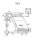
- the heat sink ABWACS comprises, as shown in Figure 4, a condenser of extensive surface 40, longitudinal furrows 41 whereof lead to a collector trough 42, an evaporator comprising a furrowed wick 43, a liquid distributor 44 for feeding liquid to the wick 43, and a thermally conductive screen 45 isolating the wick 43 from the condenser.
- a housing 46 encloses the condenser and the evaporator, providing a guide for air blown over the wick 43.
- the motor MPU is arranged for driving the pump 11, the compressor 12, the blower 14 and the evacuator 13 intermittently.
- the pump 11 is a peristaltic pump to preserve ducting integrity, and serves as a non-return valve to the heat sink ABWACS.
- the compressor 12 serves partially to condense and to raise the temperature of the vapour to facilitate operation of the heat sink ABWACS.
- the evacuator 13 serves to maintain a low pressure regime within the assembly, and is particularly described in co-pending Patent UK Application 8129028.
- the air blower 14 and the reservoir 34 associated with the heat sink ABWACS are more particularly described in co-pending UK Patent Application 8129027.
- the connector PEC includes valves by which the garment 10 is isolatable, so that it can be supplied for use already outgassed and perhaps partially evacuated.
- the assembly is prepared for use by being connected as described and shewn, when the connector PEC automatically establishes communication between ducts 24 and 30 etc, the poncho donned by someone about to enter a hot environment, and the heat sink ABWAGS and the reservoir 34 charged with water.
- the motor MPU is switched on when the environment to the garment wearer has become hot.
- the pump 11 pumps water from the sink ABWACS via the ducts 30 and 24 into the garment 10 and the compressor 12, by compressing the vapour it receives from the garment via the duct 31, raises the temperature thereof while passing it to the sink ABWACS.
- the evacuator 13, operative initially, evacuates the assembly to a required vacuum.
- the vapour is condensed and the water so formed cooled. This is principally effected by means of thermal contact over an extensive area between the working fluid and a felt in the sink moistened with water from the reservoir 34 and dried by airflow from the blower 14 and duct 33.
- the vapour in the condenser condenses and the water runs along the furrow? 41, into the trough 42 and the pipe 30.
- the pump 11 additionally acts as a non-return valve between the sink ABWAGS and the garment.
- the general low pressure of the assembly is maintained by the evacuator 32.
- Garments in accordance with the invention may be worn by personnel working in hot environments, such as military personnel, particularly tank crew and aircrew, and furnace operatives. They may be particularly useful in the aircrew context, for in the event of emergency egress over sea the connector PEC, which may be part of an ejector seat mounted personal equipment connector, may be arranged both to isolate the interior of the garment and to minimise the extent to which it and the lead 23 can act as a heat sink per se.
Landscapes
- Engineering & Computer Science (AREA)
- Physics & Mathematics (AREA)
- Mechanical Engineering (AREA)
- Thermal Sciences (AREA)
- General Engineering & Computer Science (AREA)
- Health & Medical Sciences (AREA)
- Environmental & Geological Engineering (AREA)
- General Health & Medical Sciences (AREA)
- Physical Education & Sports Medicine (AREA)
- Textile Engineering (AREA)
- Life Sciences & Earth Sciences (AREA)
- Sustainable Development (AREA)
- Central Heating Systems (AREA)
- Professional, Industrial, Or Sporting Protective Garments (AREA)
Applications Claiming Priority (2)
| Application Number | Priority Date | Filing Date | Title |
|---|---|---|---|
| GB8129023 | 1981-09-25 | ||
| GB8129023 | 1981-09-25 |
Publications (2)
| Publication Number | Publication Date |
|---|---|
| EP0076078A2 true EP0076078A2 (fr) | 1983-04-06 |
| EP0076078A3 EP0076078A3 (fr) | 1983-08-10 |
Family
ID=10524731
Family Applications (1)
| Application Number | Title | Priority Date | Filing Date |
|---|---|---|---|
| EP82304955A Withdrawn EP0076078A3 (fr) | 1981-09-25 | 1982-09-21 | Caloducs |
Country Status (1)
| Country | Link |
|---|---|
| EP (1) | EP0076078A3 (fr) |
Cited By (1)
| Publication number | Priority date | Publication date | Assignee | Title |
|---|---|---|---|---|
| US20110061839A1 (en) * | 2009-09-17 | 2011-03-17 | Munson Ryan R | Portable Heating Pad |
Family Cites Families (10)
| Publication number | Priority date | Publication date | Assignee | Title |
|---|---|---|---|---|
| US3559642A (en) * | 1968-03-01 | 1971-02-02 | Automatic Sprinkler Corp | Protective suit |
| US3543839A (en) * | 1969-05-14 | 1970-12-01 | Trw Inc | Multi-chamber controllable heat pipe |
| GB1493345A (en) * | 1974-11-05 | 1977-11-30 | Secr Defence | Inhospitable environment protective apparatus |
| US3967627A (en) * | 1974-11-18 | 1976-07-06 | Moore-Perk Corporation | Hot/cold applicator system |
| FR2307232A1 (fr) * | 1975-04-08 | 1976-11-05 | Vendome Cie | Perfectionnements aux dispositifs et aux installations de chauffage solaire |
| US4094357A (en) * | 1976-04-09 | 1978-06-13 | Kenneth C. McCord | Heat transfer blanket |
| US4067205A (en) * | 1976-07-08 | 1978-01-10 | Jack Mayhue | Super cooler for an air conditioning system |
| US4095593A (en) * | 1976-12-23 | 1978-06-20 | The United States Of America As Represented By The Administrator Of The National Aeronautics And Space Administration | Cooling system for removing metabolic heat from an hermetically sealed spacesuit |
| GB2086563A (en) * | 1980-10-21 | 1982-05-12 | Boyle & Associates R Solar Eng | Energy transfer apparatus |
| EP0059581A3 (fr) * | 1981-03-04 | 1983-03-16 | National Research Development Corporation | Caloducs |
-
1982
- 1982-09-21 EP EP82304955A patent/EP0076078A3/fr not_active Withdrawn
Cited By (2)
| Publication number | Priority date | Publication date | Assignee | Title |
|---|---|---|---|---|
| US20110061839A1 (en) * | 2009-09-17 | 2011-03-17 | Munson Ryan R | Portable Heating Pad |
| US8528833B2 (en) * | 2009-09-17 | 2013-09-10 | Ryan R. Munson | Portable heating pad |
Also Published As
| Publication number | Publication date |
|---|---|
| EP0076078A3 (fr) | 1983-08-10 |
Similar Documents
| Publication | Publication Date | Title |
|---|---|---|
| US6295648B2 (en) | Personal cooling apparatus and method | |
| US6550471B2 (en) | Heated clothing for use in cold weather and cold climate regions | |
| US2540547A (en) | Air-conditioned garment | |
| US4288396A (en) | Method and device for conditioning of breathing air for divers | |
| US20060107679A1 (en) | Portable air-conditioning unit, particularly a personal air-conditioning unit | |
| US4095593A (en) | Cooling system for removing metabolic heat from an hermetically sealed spacesuit | |
| CN104248069B (zh) | 一种可脱卸的制冷制热空调衣 | |
| EP0059581A2 (fr) | Caloducs | |
| CN202233107U (zh) | 冷暖服装 | |
| EP0076079A2 (fr) | Caloducs | |
| US2791168A (en) | Ventilating cover | |
| GB2237374A (en) | Air conditioning installation for an automotive vehicle | |
| EP0076078A2 (fr) | Caloducs | |
| GB2107853A (en) | Heat pipe assemblies | |
| EP0076080A2 (fr) | Appareil pour refroidir la tête | |
| GB2368901A (en) | Fluid conduit with enhanced thermal conducting ability | |
| GB2108261A (en) | Heat pipe assemblies | |
| WO2015075492A2 (fr) | Équipement permettant de réchauffer et de rafraîchir le corps humain | |
| CN212393907U (zh) | 智能四合一自控温防弹防水功能服 | |
| GB2121158A (en) | Heat pipe assemblies | |
| GB2107852A (en) | Heat pipe assemblies | |
| GB2076139A (en) | Heating Systems | |
| CN114391682A (zh) | 一种高能量转化并轻量型空调背心 | |
| JPH0692295A (ja) | 冷却服 | |
| CN221005557U (zh) | 可穿戴式空调系统的换热器 |
Legal Events
| Date | Code | Title | Description |
|---|---|---|---|
| PUAI | Public reference made under article 153(3) epc to a published international application that has entered the european phase |
Free format text: ORIGINAL CODE: 0009012 |
|
| AK | Designated contracting states |
Designated state(s): DE FR SE |
|
| PUAL | Search report despatched |
Free format text: ORIGINAL CODE: 0009013 |
|
| AK | Designated contracting states |
Designated state(s): DE FR SE |
|
| 17P | Request for examination filed |
Effective date: 19840111 |
|
| STAA | Information on the status of an ep patent application or granted ep patent |
Free format text: STATUS: THE APPLICATION HAS BEEN WITHDRAWN |
|
| 18W | Application withdrawn |
Withdrawal date: 19841102 |
|
| RIN1 | Information on inventor provided before grant (corrected) |
Inventor name: GRAVENEY, MICHAEL JAMES Inventor name: LARSSON, LARS ERIK |