EP0076113A2 - Wiegeapparatur mit einer Reihe von Wiegemaschinen - Google Patents
Wiegeapparatur mit einer Reihe von Wiegemaschinen Download PDFInfo
- Publication number
- EP0076113A2 EP0076113A2 EP82305045A EP82305045A EP0076113A2 EP 0076113 A2 EP0076113 A2 EP 0076113A2 EP 82305045 A EP82305045 A EP 82305045A EP 82305045 A EP82305045 A EP 82305045A EP 0076113 A2 EP0076113 A2 EP 0076113A2
- Authority
- EP
- European Patent Office
- Prior art keywords
- weighing
- articles
- hoppers
- mechanisms
- load
- Prior art date
- Legal status (The legal status is an assumption and is not a legal conclusion. Google has not performed a legal analysis and makes no representation as to the accuracy of the status listed.)
- Granted
Links
- 238000005303 weighing Methods 0.000 title claims abstract description 134
- 230000007246 mechanism Effects 0.000 claims abstract description 53
- 238000006073 displacement reaction Methods 0.000 claims 1
- 238000007689 inspection Methods 0.000 abstract description 3
- 238000009434 installation Methods 0.000 description 3
- 238000007599 discharging Methods 0.000 description 2
- 238000004806 packaging method and process Methods 0.000 description 1
Images



Classifications
-
- G—PHYSICS
- G01—MEASURING; TESTING
- G01G—WEIGHING
- G01G13/00—Weighing apparatus with automatic feed or discharge for weighing-out batches of material
- G01G13/16—Means for automatically discharging weigh receptacles under control of the weighing mechanism
-
- G—PHYSICS
- G01—MEASURING; TESTING
- G01G—WEIGHING
- G01G13/00—Weighing apparatus with automatic feed or discharge for weighing-out batches of material
- G01G13/02—Means for automatically loading weigh pans or other receptacles, e.g. disposable containers, under control of the weighing mechanism
Definitions
- This invention relates to weighing apparatus including an array of weighing machines.
- a combination computing type automatic weighing apparatus which weighs out articles by selecting a combination of the weighing mechanisms that gives a total weight closest to a preset target weight, and then discharging the articles from the weighing hoppers corresponding to the selected weighing mechanisms, whereby the weight of the discharged articles will be closest to the target weight.
- FIG. 1 is a top plan view illustrating such an automatic weighing apparatus
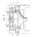
- Figure 2 is a side view of the same.
- a plurality of weighing hoppers 2 are mounted in a circular array above the circumference of the top opening of a collecting chute 1.
- Each weighing hopper 2 is operatively associated with a weighing mechanism 3 designed to weigh out articles contained in the weighing hopper 2.
- a distribution table 4 is supported on an electromagnetically operated vibrator 5 for supply troughs 6 and is set into helical reciprocating rotation.
- the supply troughs-6 are mounted radially on the outer periphery of the distribution table 4 and are vibrated by corresponding electromagnetic vibrators 7.
- Sensors 8 are used for optically sensing the quantity of the articles on the distribution table 4.
- a pool hopper 9 is provided between each weighing hopper 2 and the supply trough associated therewith.
- Each-weighing hopper 2 and the pool hopper 9 associated therewith are provided with a drive unit 12 and levers 10, 11 adapted for opening and closing the hoppers 2, 9.
- the computerized combinatorial weighing apparatus thus constructed operates as follows.
- the articles are supplied from the distribution table 4 through supply troughs 6 into pool hoppers 9 and thence into weighing hoppers 2.
- the articles thus received in the weighing hoppers 2 are weighed by the weighing mechanisms 3 associated therewith.
- a control unit, not shown, of the weighing apparatus Based on the weights measured by the weighing mechanisms 3, a control unit, not shown, of the weighing apparatus performs a combinatorial weighing operation by comparing the result of each combinatorial adding operation performed on the article weights with a preset target weight and selecting the combination of articles, known as the best combination, that gives a total weight equal to the target weight or closest to the target weight.
- the number of articles in the combination may be arbitrary or predetermined, as desired.
- the control unit then operates to open the thus selected weighing hoppers 2 by the operation of the levers 10, 11 so that the articles giving said best combination are released into the collecting chute 1 from the weighing hoppers 2 to be discharged towards a packaging machine or a bucket conveyor, not shown. This will leave the selected weighing hoppers 2 empty. Articles are then newly delivered from the corresponding pool hoppers 9 into said weighing hoppers 2 , leaving these pool hoppers 9 empty, whereupon a new supply of articles is delivered from the distribution table 4 and the corresponding supply troughs 6. The weighing operation can be continued in this manner by repeating the foregoing steps.
- Each of the weighing mechanisms 3 in the above-described automatic weighing apparatus employ weighing means that rely upon compact, highly accurate load cells.
- Each load cell includes a strain gauge affixed to upper and lower beams of a rectangular frame, and is adapted to weigh articles by relying upon a variation in the resistance of the strain gauge caused by a load applied to a load receiving member.
- the weighing mechanisms 3 are arrayed in radiating fashion so that the beams of the load cells lie along radial lines pointing to the center of the apparatus, as illustrated in Fig. 3 which is a simplified top view of the apparatus of Fig. 2 as it would appear if viewed along the line I-I with all but the weighing mechanisms 3 removed.
- Fig. 3 which is a simplified top view of the apparatus of Fig. 2 as it would appear if viewed along the line I-I with all but the weighing mechanisms 3 removed.
- An embodiment of the present invention provides an automatic weighing apparatus wherein weighing mechanisms comprised in the apparatus are not installed along radial lines. Such an arrangement can enable the space required for installation to be reduced, thereby facilitating a reduction in the overall size of the apparatus.
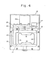
- a weighing mechanism 15 in an embodiment of the present invention includes a load cell 16 having a rectangularly shaped main body 17 which includes upper and lower beams 18, 19, and a strain gauge, not shown, attached to the inner faces of the beams 18, 19.
- the load cell 16 also has a base 20 and a load receiving portion 21.
- a rectangular support frame 22 is provided to support the load cell 16.
- the load cell 16 is disposed within the support frame 22 and has its base 20 bolted or otherwise secured to the lateral side surface of the support frame 22.
- the beams 18, 19 and the load receiving portion of the cell are left free.
- a support column 23 is affixed to the load receiving portion 21 of the load cell 16 and has an upper end portion which projects through the upper side of the support frame 22 through a hole 24 formed in the support frame.
- a weighing hopper 26 (Fig. 5) for weighing articles supplied thereto has a mounting fitting 26a secured thereto for fixedly mounting the weighing hopper 26 on the upper end of the column 23 by means of a bracket 25.
- Numeral 27 denotes a weight for the span adjustment of the load cell 16.
- the arrangement is such.that the longitudinal axes of the beams 18, 19, extending longitudinally of the load cell 16, lie parallel to the radially outward face of the weighing hopper 26.
- a load applied to the weighing hopper 26 by the weight of articles charged into the hopper is transmitted to the load receiving portion 21 of the load cell 16 through the fitting 26a, bracket 25 and support column 23.
- the strain gauge attached to the beams undergoes a change in resistance commensurate with the applied load, allowing the load, namely the weight of the articles, to be detected electrically.
- FIG. 6 An arrangement of such weighing mechanisms in an automatic weighing apparatus embodying the present invention is illustrated in Fig. 6.
- a multiplicity of the weighing mechanisms 15 are arrayed on the circumference of a circle concentric with the center of-the weighing apparatus, with the upper and lower beams 18, 19 of each incorporated load cell lying parallel with a line drawn tangent to the circle at the location of each cell.
- an article supply mechanism which may comprise the distribution table, supply troughs and pool hoppers illustrated in Fig. 2, is provided above the weighing hopper 26 supported on the weighing mechanism 15, and an article discharge apparatus, comprising a collecting chute and timing hopper, is provided below the weighing hopper 26.
- Articles supplied to the weighing hopper 26 are weighed by the weighing mechanism 15, combinations are computed based on the obtained weight values, the combination of weighing hoppers that gives a total weight equal or closest to a preset target weight is selected, and the selected weighing hoppers are caused to discharge their articles.
- the load cells incorporated within the weighing mechanisms can be inspected and repaired with facility by a technician as he faces each weighing mechanism from the outside of the weighing apparatus.
- the present invention is not limited to use in a combination computing-type automatic weighing apparatus. It may also be applied to a combination computing-type automatic counting apparatus which, having a plurality of weighing mechanisms, operates by dividing the weight of articles in each weighing mechanism by the average unit weight of each individual article to find the number of articles in the weighing hopper of each weighing mechanism, computing combinations of the numbers of articles, selecting the combination of weighing mechanisms whose weighing hoppers will give a total weight equal or closest to a preset target number, and discharging the articles from the weighing hoppers of the selected weighing mechanisms.
- the invention is not limited to such combination computing-type apparatus, but can be applied to any weighing apparatus that has a plurality of weighing mechanisms arranged to form a group, wherein the weighing mechanisms execute weighing independently of one another.
- the weighing mechanisms are arranged so as to lie parallel to respective tangent lines drawn to the circumference of the circle on which the weighing mechanisms are arrayed. Such an arrangement can facilitate inspection and repair and enhance operability. In addition, less installation space is required since the weighing mechanisms do not project from the weighing apparatus along radial lines.
Landscapes
- Physics & Mathematics (AREA)
- General Physics & Mathematics (AREA)
- Weight Measurement For Supplying Or Discharging Of Specified Amounts Of Material (AREA)
- Measurement Of Force In General (AREA)
Applications Claiming Priority (2)
| Application Number | Priority Date | Filing Date | Title |
|---|---|---|---|
| JP1981142237U JPS5846126U (ja) | 1981-09-24 | 1981-09-24 | 自動計量装置 |
| JP142237/81 | 1981-09-24 |
Publications (3)
| Publication Number | Publication Date |
|---|---|
| EP0076113A2 true EP0076113A2 (de) | 1983-04-06 |
| EP0076113A3 EP0076113A3 (en) | 1984-09-05 |
| EP0076113B1 EP0076113B1 (de) | 1987-12-02 |
Family
ID=15310615
Family Applications (1)
| Application Number | Title | Priority Date | Filing Date |
|---|---|---|---|
| EP82305045A Expired EP0076113B1 (de) | 1981-09-24 | 1982-09-24 | Wiegeapparatur mit einer Reihe von Wiegemaschinen |
Country Status (5)
| Country | Link |
|---|---|
| US (1) | US4467882A (de) |
| EP (1) | EP0076113B1 (de) |
| JP (1) | JPS5846126U (de) |
| AU (1) | AU534123B2 (de) |
| DE (1) | DE3277783D1 (de) |
Families Citing this family (8)
| Publication number | Priority date | Publication date | Assignee | Title |
|---|---|---|---|---|
| US4561509A (en) * | 1983-12-20 | 1985-12-31 | House Food Industrial Company, Limited | Combination weighing machine |
| US20070000939A1 (en) * | 2002-10-29 | 2007-01-04 | Vasilios Vasiadis | Device for handling and orientating pills or tablets in a precise manner |
| US20050092660A1 (en) * | 2003-10-29 | 2005-05-05 | Vasilios Vasiadis | Device for handling and orientating pills or tablets in a precise manner |
| US7273773B2 (en) * | 2004-01-26 | 2007-09-25 | Semiconductor Energy Laboratory Co., Ltd. | Display device, method for manufacturing thereof, and television device |
| US20070194034A1 (en) * | 2006-02-17 | 2007-08-23 | Vasilios Vasiadis | Device for printing pills, tablets or caplets in a precise manner |
| US7721897B2 (en) * | 2007-08-16 | 2010-05-25 | Kennecott Utah Copper Llc | Automated sample collection apparatus |
| US9033129B2 (en) * | 2010-11-03 | 2015-05-19 | Tna Australia Pty Limited | Product distribution chute for a weighing machine (scales) |
| CN103278231B (zh) * | 2013-05-14 | 2015-09-16 | 济南金钟电子衡器股份有限公司 | 一种称重传感器的弹性体及其制作方法 |
Family Cites Families (10)
| Publication number | Priority date | Publication date | Assignee | Title |
|---|---|---|---|---|
| US3108647A (en) * | 1961-10-31 | 1963-10-29 | Sperry Rand Corp | Self-correcting weighing machine and method |
| US4107985A (en) * | 1976-09-10 | 1978-08-22 | National Controls, Inc. | Load cell |
| US4128001A (en) * | 1977-09-16 | 1978-12-05 | Transducers, Inc. | Parallel beam load cell insensitive to point of application of load |
| US4313507A (en) * | 1978-03-09 | 1982-02-02 | Hays Gordon W | Weight portioning method and apparatus |
| DE2914449C2 (de) * | 1979-04-10 | 1985-07-25 | Soehnle-Waagen Gmbh & Co, 7157 Murrhardt | Waage mit digitaler Anzeige |
| AU534244B2 (en) * | 1979-04-19 | 1984-01-12 | Tokyo Electric Co. Ltd. | Load cell |
| JPS5696224A (en) * | 1979-12-28 | 1981-08-04 | Yamato Scale Co Ltd | Combination weighing instrument |
| JPS56100318A (en) * | 1980-01-14 | 1981-08-12 | Yamato Scale Co Ltd | Combined scale |
| GB2074329B (en) * | 1980-03-25 | 1984-05-16 | Ishida Scale Mfg Co Ltd | Automatic weighing apparatus |
| US4344492A (en) * | 1980-04-14 | 1982-08-17 | Yamato Scale Co. Ltd. | Automatic combination weighing machine with improved zero-point correction |
-
1981
- 1981-09-24 JP JP1981142237U patent/JPS5846126U/ja active Pending
-
1982
- 1982-09-21 AU AU88558/82A patent/AU534123B2/en not_active Ceased
- 1982-09-22 US US06/421,439 patent/US4467882A/en not_active Expired - Fee Related
- 1982-09-24 EP EP82305045A patent/EP0076113B1/de not_active Expired
- 1982-09-24 DE DE8282305045T patent/DE3277783D1/de not_active Expired
Also Published As
| Publication number | Publication date |
|---|---|
| DE3277783D1 (en) | 1988-01-14 |
| EP0076113A3 (en) | 1984-09-05 |
| AU534123B2 (en) | 1984-01-05 |
| US4467882A (en) | 1984-08-28 |
| AU8855882A (en) | 1983-03-31 |
| EP0076113B1 (de) | 1987-12-02 |
| JPS5846126U (ja) | 1983-03-28 |
Similar Documents
| Publication | Publication Date | Title |
|---|---|---|
| US4420051A (en) | Weighing apparatus | |
| EP0074260B1 (de) | Kombinatorische Wiegeeinrichtung | |
| EP0065820B1 (de) | Kombinatorische Wägevorrichtung | |
| EP0109844B1 (de) | Auswiegen von Chargen gemischter Artikel | |
| US4494619A (en) | Combinatorial weighing apparatus with bulk and fine feed | |
| US4522274A (en) | Combinatorial weighing method | |
| US4967856A (en) | Combination weighing machine | |
| EP0597116A1 (de) | Kombinatorisches wiegegerät mit taragewichtsabzugsfunktion | |
| EP0089835B1 (de) | Kombinatorischer Wägeapparat | |
| JPH02655Y2 (de) | ||
| EP0261406A2 (de) | Kombinatorisches Wägeverfahren und Einrichtung mit Multi-bin-Waagen | |
| EP1832857B1 (de) | Kombinationswägevorrichtung | |
| EP0076113B1 (de) | Wiegeapparatur mit einer Reihe von Wiegemaschinen | |
| JP2649073B2 (ja) | 分散供給装置の制御方法及び装置 | |
| EP0097530B1 (de) | Kombinatorischer Wägeapparat | |
| US4564103A (en) | Method and apparatus for conveying linear articles | |
| US4511009A (en) | Combinatorial weighing apparatus and method | |
| EP0076112B1 (de) | Gerät zur Korrektur von Anzeigeabweichungen bei Wiegemaschinen | |
| US4630695A (en) | Combinatorial weigher employing double group split logic | |
| EP0794476B1 (de) | Vorrichtung zur gravimetrischen Dosierung eines Gemisches | |
| JPH0257847B2 (de) | ||
| US3680649A (en) | Fluent material weighing system | |
| US4491243A (en) | Apparatus for directly and continuously weighing continuously fed powder or particle substances | |
| JPH0530493B2 (de) | ||
| EP0307188A2 (de) | Sammeln von gewogenen Artikeln |
Legal Events
| Date | Code | Title | Description |
|---|---|---|---|
| PUAI | Public reference made under article 153(3) epc to a published international application that has entered the european phase |
Free format text: ORIGINAL CODE: 0009012 |
|
| AK | Designated contracting states |
Designated state(s): DE FR GB IT |
|
| PUAL | Search report despatched |
Free format text: ORIGINAL CODE: 0009013 |
|
| AK | Designated contracting states |
Designated state(s): DE FR GB IT |
|
| 17P | Request for examination filed |
Effective date: 19850208 |
|
| 17Q | First examination report despatched |
Effective date: 19860324 |
|
| GRAA | (expected) grant |
Free format text: ORIGINAL CODE: 0009210 |
|
| AK | Designated contracting states |
Kind code of ref document: B1 Designated state(s): DE FR GB IT |
|
| ITF | It: translation for a ep patent filed | ||
| REF | Corresponds to: |
Ref document number: 3277783 Country of ref document: DE Date of ref document: 19880114 |
|
| ET | Fr: translation filed | ||
| PLBE | No opposition filed within time limit |
Free format text: ORIGINAL CODE: 0009261 |
|
| STAA | Information on the status of an ep patent application or granted ep patent |
Free format text: STATUS: NO OPPOSITION FILED WITHIN TIME LIMIT |
|
| 26N | No opposition filed | ||
| ITTA | It: last paid annual fee | ||
| PGFP | Annual fee paid to national office [announced via postgrant information from national office to epo] |
Ref country code: FR Payment date: 19950911 Year of fee payment: 14 |
|
| PGFP | Annual fee paid to national office [announced via postgrant information from national office to epo] |
Ref country code: GB Payment date: 19950915 Year of fee payment: 14 |
|
| PGFP | Annual fee paid to national office [announced via postgrant information from national office to epo] |
Ref country code: DE Payment date: 19950928 Year of fee payment: 14 |
|
| PG25 | Lapsed in a contracting state [announced via postgrant information from national office to epo] |
Ref country code: GB Effective date: 19960924 |
|
| PG25 | Lapsed in a contracting state [announced via postgrant information from national office to epo] |
Ref country code: FR Effective date: 19960930 |
|
| GBPC | Gb: european patent ceased through non-payment of renewal fee |
Effective date: 19960924 |
|
| PG25 | Lapsed in a contracting state [announced via postgrant information from national office to epo] |
Ref country code: DE Effective date: 19970603 |
|
| REG | Reference to a national code |
Ref country code: FR Ref legal event code: ST |
|
| REG | Reference to a national code |
Ref country code: FR Ref legal event code: ST |