EP0076181A1 - Dispositif mobile pour le maniement de charges - Google Patents
Dispositif mobile pour le maniement de charges Download PDFInfo
- Publication number
- EP0076181A1 EP0076181A1 EP82401641A EP82401641A EP0076181A1 EP 0076181 A1 EP0076181 A1 EP 0076181A1 EP 82401641 A EP82401641 A EP 82401641A EP 82401641 A EP82401641 A EP 82401641A EP 0076181 A1 EP0076181 A1 EP 0076181A1
- Authority
- EP
- European Patent Office
- Prior art keywords
- gear
- gear box
- fork member
- above mentioned
- vertical pillars
- Prior art date
- Legal status (The legal status is an assumption and is not a legal conclusion. Google has not performed a legal analysis and makes no representation as to the accuracy of the status listed.)
- Withdrawn
Links
Images




Classifications
-
- B—PERFORMING OPERATIONS; TRANSPORTING
- B66—HOISTING; LIFTING; HAULING
- B66F—HOISTING, LIFTING, HAULING OR PUSHING, NOT OTHERWISE PROVIDED FOR, e.g. DEVICES WHICH APPLY A LIFTING OR PUSHING FORCE DIRECTLY TO THE SURFACE OF A LOAD
- B66F9/00—Devices for lifting or lowering bulky or heavy goods for loading or unloading purposes
- B66F9/06—Devices for lifting or lowering bulky or heavy goods for loading or unloading purposes movable, with their loads, on wheels or the like, e.g. fork-lift trucks
Definitions
- a pulley 77 is provided on the side of the above mentioned vertical pillars 1 and 1a below the gear box connecting base 14.
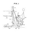
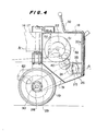
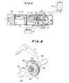
- the gear box 18 is provided with a driving wheel 19, crank pedals 20 and 20a, a transmitting mechanism transmitting the rotations of the crank pedals 20 and 20a to the above mentioned driving wheel 19, a gear mechanism transmitting the rotations of the crank pedals 20 and 20a to a wire drum 22 winding a wire 21 connected to the fork mechanism 2 to lift and lower the fork member 2, a switching mechanism for switching the rotations of the crank pedals to the transmitting mechanism or the gear mechanism and a braking mechanism preventing the reverse rotation of the wire drum 22.
- one of the above mentioned speed changing gears 25 and 26 is made larger than and integral with the other and they are so formed as to be able to be slid along the driving shaft 23 by a switching lever 32 provided from above the gear box 18.
- pins 34 are provided on the sprocket 24 side of the speed changing gears 25 and 26 and holes 35 in which the pins 34 are to be respectively inserted are provided in the sprocket 24 opposed to the pins 24. This is a so-called clutch.
- the winding of the wire 21 by the wire drum 22 shall be described in the following.
- the brake flange 46 is prevented by a flange 50 formed on the rotary shaft 36 from moving to the gear 40 side.
- the reference numeral 53 denotes a guide roller leading the wire 21 to the wire drum 22.
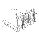
- the wire 21 is secured at one end to the wire fixing part 9 provided on the upper frame 8 of the vertical pillars 1 and 1a and is wound on the wire drum 22 through the pulley 7 provided on the form member 2, pulley 10 provided on the upper frame 8 and pulley 77 and guide rollers 53 provided on the gear box connecting base 14 in turn.
- a steering wheel 54 is secured to the handle 16, wires 55 and 56 are pulled out on both sides of the steering wheel 54, are fixed at the tips to the steering wheel 54, are crossed with each other in the course through tubes 57 and 58 to be led onto the gear box connecting base 14, there the tubes 57 and 58 are fixed and only the wires 55 and 56 are crossed with each other to be fixed to a bracket 64 on the gear box 18 side through a wheel 59 provided in the shaft 17 part.
- the reference numeral 60 denotes a brake lever connected to a disk brake 62 through a wire 61 enclosed in a tube as shown in Figs. 1 and 13.
- the reference numeral 63 denotes a driving seat.
- the rotary shaft 36, gear 38, brake flanges 42 and 46, brake liners 43 and 45 and ratchet gear 44 will integrally rotate, the gear 40 fitted to the rotary shaft 36 will also rotate, the gear 39 of the wire drum 22 meshed with the gear 40 will be rotated and the wire drum 22 will be rotated to wind the wire 21 and lift the fork member 2.
- the ratchet pawl 51 will be automatically engaged with the ratchet gear 44 in the lifted position of the fork member 2 and the fork member 2 will not naturally lower.
- the lowering of the fork member 2 shall be described in the following.
- the crank pedals 20 and 20a are reversely rotated.
- the gear 37 or 38 on the rotary shaft 36 will be reversely rotated and, at the same time, the brake flange 42 will be also reversely rotated.
- the fork member 2 will be able to be continuously lowered and will be able to be easily stopped in the position of a required height.
- the present invention uses no such fuel as petroleum for a power source, is very economical, can be provided very cheaply, can be operated easily by anyone, is safe and is very high in the industrial utilizability.
Landscapes
- Engineering & Computer Science (AREA)
- Transportation (AREA)
- Structural Engineering (AREA)
- Civil Engineering (AREA)
- Life Sciences & Earth Sciences (AREA)
- Geology (AREA)
- Mechanical Engineering (AREA)
- Forklifts And Lifting Vehicles (AREA)
Applications Claiming Priority (2)
| Application Number | Priority Date | Filing Date | Title |
|---|---|---|---|
| JP143077/81 | 1981-09-10 | ||
| JP14307781A JPS5847799A (ja) | 1981-09-10 | 1981-09-10 | 走行荷役装置 |
Publications (1)
| Publication Number | Publication Date |
|---|---|
| EP0076181A1 true EP0076181A1 (fr) | 1983-04-06 |
Family
ID=15330372
Family Applications (1)
| Application Number | Title | Priority Date | Filing Date |
|---|---|---|---|
| EP82401641A Withdrawn EP0076181A1 (fr) | 1981-09-10 | 1982-09-09 | Dispositif mobile pour le maniement de charges |
Country Status (2)
| Country | Link |
|---|---|
| EP (1) | EP0076181A1 (fr) |
| JP (1) | JPS5847799A (fr) |
Cited By (3)
| Publication number | Priority date | Publication date | Assignee | Title |
|---|---|---|---|---|
| US5044473A (en) * | 1989-09-18 | 1991-09-03 | Gripe Thomas L | Elevator work station apparatus |
| CN111039232A (zh) * | 2019-12-06 | 2020-04-21 | 杭州优智物联科技有限公司 | 一种快速装卸货物的叉车装置及方法 |
| CN114952565A (zh) * | 2022-05-25 | 2022-08-30 | 唐山晶玉科技股份有限公司 | 一种多线切割机上料及槽轮更换装置 |
Citations (8)
| Publication number | Priority date | Publication date | Assignee | Title |
|---|---|---|---|---|
| CH246077A (de) * | 1945-11-09 | 1946-12-15 | Contelly Eduard | Fahrbarer Fassheber. |
| FR1059182A (fr) * | 1952-06-24 | 1954-03-23 | Chariot élévateur pour garages | |
| FR1164709A (fr) * | 1957-01-10 | 1958-10-14 | Hersan & Cie | Perfectionnement aux engins de manutention, notamment aux chariots élévateurs |
| FR1229113A (fr) * | 1958-06-14 | 1960-09-05 | Chariot élévateur à fourche, perfectionné | |
| FR1299096A (fr) * | 1961-06-09 | 1962-07-20 | Schlumberger Cie N | Chariot de manutention |
| US3187841A (en) * | 1962-06-20 | 1965-06-08 | Modern Hydraulics Inc | Fork lift vehicle |
| DE2553144A1 (de) * | 1974-11-26 | 1976-08-12 | Handa Heavy Industry Co | Muskelkraft-gabelstapler |
| WO1981003482A1 (fr) * | 1981-04-06 | 1981-12-10 | Japan Steels Corp | Appareil de manipulation de charges mobiles |
-
1981
- 1981-09-10 JP JP14307781A patent/JPS5847799A/ja active Pending
-
1982
- 1982-09-09 EP EP82401641A patent/EP0076181A1/fr not_active Withdrawn
Patent Citations (8)
| Publication number | Priority date | Publication date | Assignee | Title |
|---|---|---|---|---|
| CH246077A (de) * | 1945-11-09 | 1946-12-15 | Contelly Eduard | Fahrbarer Fassheber. |
| FR1059182A (fr) * | 1952-06-24 | 1954-03-23 | Chariot élévateur pour garages | |
| FR1164709A (fr) * | 1957-01-10 | 1958-10-14 | Hersan & Cie | Perfectionnement aux engins de manutention, notamment aux chariots élévateurs |
| FR1229113A (fr) * | 1958-06-14 | 1960-09-05 | Chariot élévateur à fourche, perfectionné | |
| FR1299096A (fr) * | 1961-06-09 | 1962-07-20 | Schlumberger Cie N | Chariot de manutention |
| US3187841A (en) * | 1962-06-20 | 1965-06-08 | Modern Hydraulics Inc | Fork lift vehicle |
| DE2553144A1 (de) * | 1974-11-26 | 1976-08-12 | Handa Heavy Industry Co | Muskelkraft-gabelstapler |
| WO1981003482A1 (fr) * | 1981-04-06 | 1981-12-10 | Japan Steels Corp | Appareil de manipulation de charges mobiles |
Cited By (5)
| Publication number | Priority date | Publication date | Assignee | Title |
|---|---|---|---|---|
| US5044473A (en) * | 1989-09-18 | 1991-09-03 | Gripe Thomas L | Elevator work station apparatus |
| CN111039232A (zh) * | 2019-12-06 | 2020-04-21 | 杭州优智物联科技有限公司 | 一种快速装卸货物的叉车装置及方法 |
| CN111039232B (zh) * | 2019-12-06 | 2024-01-05 | 浙江优智物联科技有限公司 | 一种快速装卸货物的叉车装置及方法 |
| CN114952565A (zh) * | 2022-05-25 | 2022-08-30 | 唐山晶玉科技股份有限公司 | 一种多线切割机上料及槽轮更换装置 |
| CN114952565B (zh) * | 2022-05-25 | 2024-02-13 | 唐山晶玉科技股份有限公司 | 一种多线切割机上料及槽轮更换装置 |
Also Published As
| Publication number | Publication date |
|---|---|
| JPS5847799A (ja) | 1983-03-19 |
Similar Documents
| Publication | Publication Date | Title |
|---|---|---|
| US4695010A (en) | Levelwind mechanism | |
| KR20110098218A (ko) | 마찰차를 이용한 호이스트 | |
| CN112542808A (zh) | 一种电力工程建设用线缆敷设装置 | |
| CN208265658U (zh) | 一种大型货物的搬运装置 | |
| CN206203771U (zh) | 潜入式agv小车升降杆 | |
| US1991576A (en) | Industrial truck | |
| CN220334424U (zh) | 一种通用型立式放线装置 | |
| CN205633962U (zh) | 热处理转运小车 | |
| CN221828496U (zh) | 一种电动紧线机 | |
| US2178879A (en) | Platform operating means | |
| CN211846960U (zh) | 一种安全载物提升机 | |
| CN202704696U (zh) | 测井电缆自动倒绳机 | |
| CN217895046U (zh) | 智能叉车电动举升结构 | |
| KR930008534Y1 (ko) | 수문의 하강속도 제어용 구동력 제동 장치 | |
| JPH11246007A (ja) | 搬送車 | |
| KR100517326B1 (ko) | 상 하향 수직구동식 현수막 게시 장치 | |
| KR101165774B1 (ko) | 오징어 채낚기 자동 리프팅장치 | |
| CN209778193U (zh) | 一种可全向移动的叉车 | |
| CN224105501U (zh) | 一种能自动左右调节的叉臂 | |
| CN219341558U (zh) | 一种液压绞车 | |
| CN216523340U (zh) | 一种新型石油开采用便于移动的换热器 | |
| CN222225635U (zh) | 一种无极调速钻修机用倒绳机 | |
| CN218704225U (zh) | 一种装箱流水线设备 | |
| DE663504C (de) | Windwerk fuer Kraftfahrzeuge | |
| CN115788123B (zh) | 垂直循环式立体车库 |
Legal Events
| Date | Code | Title | Description |
|---|---|---|---|
| PUAI | Public reference made under article 153(3) epc to a published international application that has entered the european phase |
Free format text: ORIGINAL CODE: 0009012 |
|
| AK | Designated contracting states |
Designated state(s): AT BE CH DE FR GB IT LI NL SE |
|
| 17P | Request for examination filed |
Effective date: 19830711 |
|
| STAA | Information on the status of an ep patent application or granted ep patent |
Free format text: STATUS: THE APPLICATION IS DEEMED TO BE WITHDRAWN |
|
| 18D | Application deemed to be withdrawn |
Effective date: 19841201 |
|
| RIN1 | Information on inventor provided before grant (corrected) |
Inventor name: DOUGLAS, FIRC/O JAPAN STEELS CORPORATION K.K. |