EP0076183A1 - Elektrische Verteilungsvorrichtung - Google Patents
Elektrische Verteilungsvorrichtung Download PDFInfo
- Publication number
- EP0076183A1 EP0076183A1 EP82401647A EP82401647A EP0076183A1 EP 0076183 A1 EP0076183 A1 EP 0076183A1 EP 82401647 A EP82401647 A EP 82401647A EP 82401647 A EP82401647 A EP 82401647A EP 0076183 A1 EP0076183 A1 EP 0076183A1
- Authority
- EP
- European Patent Office
- Prior art keywords
- housings
- junction box
- distribution device
- electricity distribution
- connection
- Prior art date
- Legal status (The legal status is an assumption and is not a legal conclusion. Google has not performed a legal analysis and makes no representation as to the accuracy of the status listed.)
- Granted
Links
- 238000009826 distribution Methods 0.000 title claims abstract description 19
- 239000004020 conductor Substances 0.000 claims abstract description 23
- 238000005192 partition Methods 0.000 claims abstract description 12
- 230000037431 insertion Effects 0.000 claims abstract 2
- 238000003780 insertion Methods 0.000 claims abstract 2
- 230000005611 electricity Effects 0.000 claims description 11
- 239000013013 elastic material Substances 0.000 claims description 2
- 230000000149 penetrating effect Effects 0.000 claims 1
- 239000012858 resilient material Substances 0.000 abstract 1
- 210000002105 tongue Anatomy 0.000 description 9
- 230000004048 modification Effects 0.000 description 3
- 238000012986 modification Methods 0.000 description 3
- 230000000295 complement effect Effects 0.000 description 2
- 238000004519 manufacturing process Methods 0.000 description 2
- 239000002184 metal Substances 0.000 description 2
- 229910001369 Brass Inorganic materials 0.000 description 1
- 239000010951 brass Substances 0.000 description 1
- 238000002788 crimping Methods 0.000 description 1
- 238000009434 installation Methods 0.000 description 1
- 239000011810 insulating material Substances 0.000 description 1
- 239000007787 solid Substances 0.000 description 1
- 238000003466 welding Methods 0.000 description 1
Images



Classifications
-
- H—ELECTRICITY
- H02—GENERATION; CONVERSION OR DISTRIBUTION OF ELECTRIC POWER
- H02G—INSTALLATION OF ELECTRIC CABLES OR LINES, OR OF COMBINED OPTICAL AND ELECTRIC CABLES OR LINES
- H02G3/00—Installations of electric cables or lines or protective tubing therefor in or on buildings, equivalent structures or vehicles
- H02G3/28—Installations of cables, lines, or separate protective tubing therefor in conduits or ducts pre-established in walls, ceilings or floors
- H02G3/283—Installations of cables, lines, or separate protective tubing therefor in conduits or ducts pre-established in walls, ceilings or floors in floors
- H02G3/285—Installations of cables, lines, or separate protective tubing therefor in conduits or ducts pre-established in walls, ceilings or floors in floors in modular floors, e.g. access floors
-
- H—ELECTRICITY
- H01—ELECTRIC ELEMENTS
- H01R—ELECTRICALLY-CONDUCTIVE CONNECTIONS; STRUCTURAL ASSOCIATIONS OF A PLURALITY OF MUTUALLY-INSULATED ELECTRICAL CONNECTING ELEMENTS; COUPLING DEVICES; CURRENT COLLECTORS
- H01R31/00—Coupling parts supported only by co-operation with counterpart
- H01R31/02—Intermediate parts for distributing energy to two or more circuits in parallel, e.g. splitter
-
- H—ELECTRICITY
- H01—ELECTRIC ELEMENTS
- H01R—ELECTRICALLY-CONDUCTIVE CONNECTIONS; STRUCTURAL ASSOCIATIONS OF A PLURALITY OF MUTUALLY-INSULATED ELECTRICAL CONNECTING ELEMENTS; COUPLING DEVICES; CURRENT COLLECTORS
- H01R25/00—Coupling parts adapted for simultaneous co-operation with two or more identical counterparts, e.g. for distributing energy to two or more circuits
- H01R25/003—Coupling parts adapted for simultaneous co-operation with two or more identical counterparts, e.g. for distributing energy to two or more circuits the coupling part being secured only to wires or cables
Definitions
- the invention relates to a current distribution device capable of being modified, supplemented or dismantled without requiring any deep intervention on the premises which it is intended to equip, and comprising junction boxes provided with first connection members and flexible conductors each having two ends respectively equipped with second connecting members capable of cooperating with the first members.
- Such systems find their use, in particular, for the equipment of premises, offices, furniture, with or without demountable partitions, as well as for a mode of distribution of the current in which such systems are placed under a raised floor or above a false ceiling made up of removable elements.
- connection plugs of the different stages are made by brass pins, which are housed in holes provided in the connection plugs.
- This arrangement requires the manufacture of a two-part case which can be assembled after having introduced the plugs and the electrical connection pins between the plugs of one stage and those of the upper stage.
- this type of device increases the number of contacts because there are plug-pin contacts which are added to the contacts of the connection plugs of the junction box with the plugs of the flexible conductors.
- the invention aims primarily to provide a distribution system which is simple, inexpensive, quick to assemble.
- An additional aim is to provide a device which is adapted at any time to a modification and an extension of the number of its supply outlets.
- a third object of the invention consists in preventing the association of the elements of the system from causing short-circuits without necessarily calling for measures such as those which require a chosen coloration of the different conductors, and in providing a system which can be installed and modified in complete safety by non-specialized personnel and possibly with little warning of the dangers presented by electricity.
- the electricity distribution device comprises at least one junction box and a plurality of flexible conductors comprising, at at least one end, a junction plug
- the junction box is constituted by a prismatic insulating body comprising a plurality of stacks of superimposed housings, electrically insulated by horizontal dividing partitions, each stack being separated from another by a vertical dividing partition, said housings opening onto two opposite parallel faces
- said body comprising a multiplicity of means for introducing and fixing a multiplicity of first connection elements in a number equal to that of the housings of a battery, said connection elements being arranged parallel one above the other and made up of at least one piece, cut from a flat, conductive and elastic material, the shape of which comprises a cross member secured to at least two pairs of branches perpendicular to the cross member, the branches of a pair being arranged symmetrically with respect to the cross member and placed in the same housing while the branches of two different pairs are placed in housing belonging to two different batteries
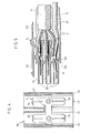
- Figures 1, 2, 3 and 4 show a junction box comprising an insulating body 1 forming a hollow prismatic solid open at two ends 18, 19 whose internal volume is shared by a succession of horizontal partitions 10 and a vertical partition 11 of symmetry so as to form two successions of housings 17, each housing opening onto each of the open faces 18, 19 of the body.
- the housings of the same succession which, opening onto one face of the body, are intended to accommodate a connection element described below having a succession of plugs whose volume and shape adapt to those of the housings of the junction box.
- These housings are provided with grooves 16 which cooperate with ribs provided on the male connection plugs so as to prevent unskilled personnel from connecting two incoming conductors to the same junction box.
- a groove 111 provided in the vertical partition of the housing approximately halfway up each housing allows the introduction of a connecting piece 2 consisting of two elastic pieces 27, 28 cut from a sheet of conductive metal, assembled together by crimping or welding or any other means.
- This connection piece 2 advantageously having the shape of an H as can be seen in FIG. 4.
- the transverse portion 22 of the H is housed in the groove 111.
- connection piece is fixed in the housing by any means; advantageously we can use teeth 21 provided on the sides of the connection piece and which cooperate with grooves 15 provided on the internal lateral faces of the housing, halfway up each housing opening onto an open end.
- the housing 1 also comprises at its lower part, a rib 12 in the shape of a T or dovetail and at its upper part a groove 14 of shape complementary to the shape of a T or in the dovetail.
- the groove 14 of a housing cooperates with the rib 12 of another housing to produce stacks of junction boxes.
- fixing means not shown to allow the attachment of the housing to a piece of furniture, a partition, a floor or a false ceiling.
- two eyelets 13 are provided intended to receive an elastic tongue integral with the connection plug so as to snap-lock the plug on the housing.
- FIG. 5 represents a connection plug intended to come to cooperate with a succession of connection elements placed in a succession of superimposed housings in the same vertical plane.
- This sheet comprises a prismatic body 3 of insulating material having a succession of hollow receptacles 34 formed by walls whose external shape is complementary to the shape of the housings 17 of the junction box 1, and of external dimension less than the internal dimension of the housings 17.
- External walls comprising ribs arranged so as to cooperate with the grooves of the housing of the housing in order to disarm an uninformed manipulator.
- Open housings 30 formed in the hollow of the receptacles are intended to receive tongues 31 of conductive metal, one end of which is connected by known means to a conductive wire 4 secured to a flexible conductor 5.
- a lug 310 formed in the tongue 31 and coming to bear on a shoulder 301 of the body 3 prevents the tongues from coming out of their housings before the overmolding operation.
- the body 3 also includes a tongue 32 provided with a shoulder and intended to snap into place with an eyelet 13 at the junction box.
- Another direction tongue 33 parallel to the flexible conductor serves as a label holder.
- an overmolding 6 immobilizes the tongues and the conducting wires 4 relative to the body 3.
- each tab 31 is introduced into the clamp constituted by one of the branches 23, 24, 25, 26 of each piece 27, 28 of a connection element placed in different horizontal planes of the junction box.
- a tongue pinched by the branches of the parts of a connection element is electrically connected via the other branches with other tongues belonging to other plugs.
- FIG. 6 represents an example of application among those cited above in which a current supply conductor 50 is connected by means of a plug 3 to a junction 1 allowing the distribution of the power supply via plugs 3, to flexible conductors 51, 52, 53, which pass under raised floors 7 or in furniture 8 to distribute the current at other necessary points .
- each flexible conductor 51, 52, 53 and the supply conductor 50 comprise at least one end of each conductor 50, 51, 52, 53, a plug 3 with a grounding wire, indicated by the marks 400, 401, 402, 403.
- connection element 2 consists of a single cut-out piece 27 and that each second connection element 31 mounted in the plug is made up of two elastic blades pinching a branch of the part 27.
Landscapes
- Engineering & Computer Science (AREA)
- Architecture (AREA)
- Civil Engineering (AREA)
- Structural Engineering (AREA)
- Connection Or Junction Boxes (AREA)
- Connector Housings Or Holding Contact Members (AREA)
Applications Claiming Priority (2)
| Application Number | Priority Date | Filing Date | Title |
|---|---|---|---|
| FR8117555A FR2513030A1 (fr) | 1981-09-17 | 1981-09-17 | Dispositif de distribution electrique |
| FR8117555 | 1981-09-17 |
Publications (2)
| Publication Number | Publication Date |
|---|---|
| EP0076183A1 true EP0076183A1 (de) | 1983-04-06 |
| EP0076183B1 EP0076183B1 (de) | 1985-02-20 |
Family
ID=9262228
Family Applications (1)
| Application Number | Title | Priority Date | Filing Date |
|---|---|---|---|
| EP19820401647 Expired EP0076183B1 (de) | 1981-09-17 | 1982-09-10 | Elektrische Verteilungsvorrichtung |
Country Status (5)
| Country | Link |
|---|---|
| EP (1) | EP0076183B1 (de) |
| DE (1) | DE3262436D1 (de) |
| ES (1) | ES275412Y (de) |
| FR (1) | FR2513030A1 (de) |
| IE (1) | IE53439B1 (de) |
Cited By (3)
| Publication number | Priority date | Publication date | Assignee | Title |
|---|---|---|---|---|
| FR2651610A1 (fr) * | 1989-09-05 | 1991-03-08 | Air Lb International Sa | Module de connexion pour conducteurs electriques. |
| WO1991020115A1 (en) * | 1990-06-14 | 1991-12-26 | Minnesota Mining And Manufacturing Company | Two cord connector system for prefabricated panels |
| FR2708155A1 (fr) * | 1993-07-21 | 1995-01-27 | Nozick Jacques | Réceptacle de sol pour plancher technique surélevé, destiné au câblage modulaire. |
Families Citing this family (1)
| Publication number | Priority date | Publication date | Assignee | Title |
|---|---|---|---|---|
| GB2206458B (en) * | 1987-06-25 | 1991-03-27 | Kyodo Denki | Cable lead-out structure for free cable laying on a floor. |
Citations (8)
| Publication number | Priority date | Publication date | Assignee | Title |
|---|---|---|---|---|
| FR1098984A (fr) * | 1953-04-25 | 1955-08-29 | Busch Jaeger Duerener Metall | Pièce intermédiaire pour juxtaposer des prises de courant intérieures montées sous enduit |
| FR1340207A (fr) * | 1962-07-03 | 1963-10-18 | Acec | Traversée pour canalisation électrique |
| FR2171295A1 (de) * | 1972-02-09 | 1973-09-21 | Amp Inc | |
| US3873177A (en) * | 1972-03-30 | 1975-03-25 | Electronic Eng Co | Junction box connector assembly |
| US4109988A (en) * | 1977-07-15 | 1978-08-29 | Olson Ernest E | Duplex outlet device |
| FR2400786A1 (fr) * | 1977-08-18 | 1979-03-16 | Miller Herman Inc | Dispositif de distribution de courant electrique pour des postes de travail dans un systeme de cloisonnement |
| FR2483136A1 (fr) * | 1980-05-22 | 1981-11-27 | Strasbourg Forges | Dispositif de connexion electrique notamment pour meubles de bureau |
| US4313646A (en) * | 1980-02-25 | 1982-02-02 | Amp Incorporated | Power distribution system |
-
1981
- 1981-09-17 FR FR8117555A patent/FR2513030A1/fr active Granted
-
1982
- 1982-09-09 IE IE221682A patent/IE53439B1/en not_active IP Right Cessation
- 1982-09-10 DE DE8282401647T patent/DE3262436D1/de not_active Expired
- 1982-09-10 EP EP19820401647 patent/EP0076183B1/de not_active Expired
- 1982-09-16 ES ES1982275412U patent/ES275412Y/es not_active Expired
Patent Citations (8)
| Publication number | Priority date | Publication date | Assignee | Title |
|---|---|---|---|---|
| FR1098984A (fr) * | 1953-04-25 | 1955-08-29 | Busch Jaeger Duerener Metall | Pièce intermédiaire pour juxtaposer des prises de courant intérieures montées sous enduit |
| FR1340207A (fr) * | 1962-07-03 | 1963-10-18 | Acec | Traversée pour canalisation électrique |
| FR2171295A1 (de) * | 1972-02-09 | 1973-09-21 | Amp Inc | |
| US3873177A (en) * | 1972-03-30 | 1975-03-25 | Electronic Eng Co | Junction box connector assembly |
| US4109988A (en) * | 1977-07-15 | 1978-08-29 | Olson Ernest E | Duplex outlet device |
| FR2400786A1 (fr) * | 1977-08-18 | 1979-03-16 | Miller Herman Inc | Dispositif de distribution de courant electrique pour des postes de travail dans un systeme de cloisonnement |
| US4313646A (en) * | 1980-02-25 | 1982-02-02 | Amp Incorporated | Power distribution system |
| FR2483136A1 (fr) * | 1980-05-22 | 1981-11-27 | Strasbourg Forges | Dispositif de connexion electrique notamment pour meubles de bureau |
Cited By (3)
| Publication number | Priority date | Publication date | Assignee | Title |
|---|---|---|---|---|
| FR2651610A1 (fr) * | 1989-09-05 | 1991-03-08 | Air Lb International Sa | Module de connexion pour conducteurs electriques. |
| WO1991020115A1 (en) * | 1990-06-14 | 1991-12-26 | Minnesota Mining And Manufacturing Company | Two cord connector system for prefabricated panels |
| FR2708155A1 (fr) * | 1993-07-21 | 1995-01-27 | Nozick Jacques | Réceptacle de sol pour plancher technique surélevé, destiné au câblage modulaire. |
Also Published As
| Publication number | Publication date |
|---|---|
| ES275412Y (es) | 1984-10-01 |
| EP0076183B1 (de) | 1985-02-20 |
| IE822216L (en) | 1983-03-17 |
| FR2513030B1 (de) | 1984-12-07 |
| ES275412U (es) | 1984-02-16 |
| DE3262436D1 (en) | 1985-03-28 |
| FR2513030A1 (fr) | 1983-03-18 |
| IE53439B1 (en) | 1988-11-09 |
Similar Documents
| Publication | Publication Date | Title |
|---|---|---|
| EP0735629B1 (de) | Vorrichtung für die Verbindung von elektrischen Leitungsdrähten und Anschlussblock ausgerüstet mit obiger Vorrichtung | |
| EP0123590A1 (de) | Verbinder | |
| FR2930848A3 (fr) | Prise electrique multiple de securite | |
| FR2535912A1 (fr) | Rail profile de fixation d'appareillage pour coffret ou tableau electrique de distribution a basse tension | |
| EP0109876B1 (de) | Modulartige Verteilungsanordnung für elektrische Energie | |
| FR2748352A1 (fr) | Socle de branchement pour reseau de transmission, en particulier pour reseau telephonique ou informatique | |
| EP0578576B1 (de) | Elektrische Anschlussklemme | |
| EP0076183B1 (de) | Elektrische Verteilungsvorrichtung | |
| EP0868737A1 (de) | Vorrichtung zum anschliessen eines aussenleiters, wie ein kabel zu eine kontaktfläche eines elektrisches gerät | |
| FR2631490A1 (fr) | Connecteur electrique composite et procede de chargement de conducteurs dans ce connecteur | |
| FR3025947A1 (fr) | Corps isolant pour connecteur debrochable | |
| EP1026782B1 (de) | Verbindungsblock für elektrische Geräte | |
| EP0114539B1 (de) | Verbindungsvorrichtung mit Sammelschienen | |
| EP0627793A1 (de) | Aufeinandergestapelte Verbindungselemente umfassender Verbindungszusammenbau | |
| EP1422799B1 (de) | Energieverteileranordnung für elektrische Geräte | |
| FR2766628A1 (fr) | Peigne d'interconnexion pour alignement de bornes de raccordement electrique d'un appareillage et module(s) de logement d'appareillage correspondant(s) | |
| EP2849295B1 (de) | Elektrische Verteilungsanordnung mit einem mehrpoligen Stromverteilungskamm. | |
| EP1107363B1 (de) | Monopolarer Modularerverteiler | |
| FR2621424A1 (fr) | Dispositif mecanique d'assemblage avec autocentrage de modules d'appareillage electrique | |
| EP2383849A1 (de) | Vertikale elektrisch leitenden Verbindungsvorrichtung | |
| FR2636782A1 (fr) | Dispositif de raccordement par peigne de pontage d'appareils electriques modulaires, et procede de fabrication d'un tel peigne | |
| FR2778502A1 (fr) | Connecteur electrique a grille de protection des contacts | |
| FR2877502A1 (fr) | Element de bornier et connecteur sans vis. | |
| EP0315558B1 (de) | Elektrifizierte Gleitschiene für eine bewegbare elektrische Steckdose | |
| EP1999823B1 (de) | Niederspannungsverbinder |
Legal Events
| Date | Code | Title | Description |
|---|---|---|---|
| PUAI | Public reference made under article 153(3) epc to a published international application that has entered the european phase |
Free format text: ORIGINAL CODE: 0009012 |
|
| 17P | Request for examination filed |
Effective date: 19820915 |
|
| AK | Designated contracting states |
Designated state(s): BE DE GB IT NL |
|
| ITF | It: translation for a ep patent filed | ||
| GRAA | (expected) grant |
Free format text: ORIGINAL CODE: 0009210 |
|
| AK | Designated contracting states |
Designated state(s): BE DE GB IT NL |
|
| REF | Corresponds to: |
Ref document number: 3262436 Country of ref document: DE Date of ref document: 19850328 |
|
| PLBE | No opposition filed within time limit |
Free format text: ORIGINAL CODE: 0009261 |
|
| STAA | Information on the status of an ep patent application or granted ep patent |
Free format text: STATUS: NO OPPOSITION FILED WITHIN TIME LIMIT |
|
| 26N | No opposition filed | ||
| ITTA | It: last paid annual fee | ||
| PGFP | Annual fee paid to national office [announced via postgrant information from national office to epo] |
Ref country code: NL Payment date: 19960819 Year of fee payment: 15 |
|
| PGFP | Annual fee paid to national office [announced via postgrant information from national office to epo] |
Ref country code: GB Payment date: 19960903 Year of fee payment: 15 |
|
| PGFP | Annual fee paid to national office [announced via postgrant information from national office to epo] |
Ref country code: DE Payment date: 19960919 Year of fee payment: 15 |
|
| PGFP | Annual fee paid to national office [announced via postgrant information from national office to epo] |
Ref country code: BE Payment date: 19961009 Year of fee payment: 15 |
|
| PG25 | Lapsed in a contracting state [announced via postgrant information from national office to epo] |
Ref country code: GB Free format text: LAPSE BECAUSE OF NON-PAYMENT OF DUE FEES Effective date: 19970910 |
|
| PG25 | Lapsed in a contracting state [announced via postgrant information from national office to epo] |
Ref country code: BE Free format text: LAPSE BECAUSE OF NON-PAYMENT OF DUE FEES Effective date: 19970930 |
|
| BERE | Be: lapsed |
Owner name: LA TELEMECANIQUE ELECTRIQUE Effective date: 19970930 |
|
| PG25 | Lapsed in a contracting state [announced via postgrant information from national office to epo] |
Ref country code: NL Free format text: LAPSE BECAUSE OF NON-PAYMENT OF DUE FEES Effective date: 19980401 |
|
| GBPC | Gb: european patent ceased through non-payment of renewal fee |
Effective date: 19970910 |
|
| NLV4 | Nl: lapsed or anulled due to non-payment of the annual fee |
Effective date: 19980401 |
|
| PG25 | Lapsed in a contracting state [announced via postgrant information from national office to epo] |
Ref country code: DE Free format text: LAPSE BECAUSE OF NON-PAYMENT OF DUE FEES Effective date: 19980603 |