EP0076194A1 - Système d'équilibrage d'un couple de balourd, utilisation d'un tel système pour une antenne de radar aéroporté, et antenne équilibrée par un tel système - Google Patents
Système d'équilibrage d'un couple de balourd, utilisation d'un tel système pour une antenne de radar aéroporté, et antenne équilibrée par un tel système Download PDFInfo
- Publication number
- EP0076194A1 EP0076194A1 EP82401686A EP82401686A EP0076194A1 EP 0076194 A1 EP0076194 A1 EP 0076194A1 EP 82401686 A EP82401686 A EP 82401686A EP 82401686 A EP82401686 A EP 82401686A EP 0076194 A1 EP0076194 A1 EP 0076194A1
- Authority
- EP
- European Patent Office
- Prior art keywords
- rotation
- unbalance
- balancing
- axis
- antenna
- Prior art date
- Legal status (The legal status is an assumption and is not a legal conclusion. Google has not performed a legal analysis and makes no representation as to the accuracy of the status listed.)
- Granted
Links
- 238000011067 equilibration Methods 0.000 title 1
- 230000003042 antagnostic effect Effects 0.000 claims abstract description 6
- 230000005540 biological transmission Effects 0.000 claims description 8
- 239000012530 fluid Substances 0.000 claims description 4
- 238000006073 displacement reaction Methods 0.000 claims 2
- 238000004804 winding Methods 0.000 abstract 1
- 230000007246 mechanism Effects 0.000 description 7
- 230000001133 acceleration Effects 0.000 description 5
- 230000005484 gravity Effects 0.000 description 2
- 239000005557 antagonist Substances 0.000 description 1
Images


Classifications
-
- F—MECHANICAL ENGINEERING; LIGHTING; HEATING; WEAPONS; BLASTING
- F16—ENGINEERING ELEMENTS AND UNITS; GENERAL MEASURES FOR PRODUCING AND MAINTAINING EFFECTIVE FUNCTIONING OF MACHINES OR INSTALLATIONS; THERMAL INSULATION IN GENERAL
- F16F—SPRINGS; SHOCK-ABSORBERS; MEANS FOR DAMPING VIBRATION
- F16F15/00—Suppression of vibrations in systems; Means or arrangements for avoiding or reducing out-of-balance forces, e.g. due to motion
- F16F15/28—Counterweights, i.e. additional weights counterbalancing inertia forces induced by the reciprocating movement of masses in the system, e.g. of pistons attached to an engine crankshaft; Attaching or mounting same
-
- H—ELECTRICITY
- H01—ELECTRIC ELEMENTS
- H01Q—ANTENNAS, i.e. RADIO AERIALS
- H01Q3/00—Arrangements for changing or varying the orientation or the shape of the directional pattern of the waves radiated from an antenna or antenna system
- H01Q3/02—Arrangements for changing or varying the orientation or the shape of the directional pattern of the waves radiated from an antenna or antenna system using mechanical movement of antenna or antenna system as a whole
- H01Q3/08—Arrangements for changing or varying the orientation or the shape of the directional pattern of the waves radiated from an antenna or antenna system using mechanical movement of antenna or antenna system as a whole for varying two co-ordinates of the orientation
Definitions
- the present invention relates to a system for balancing an unbalance torque, its use for balancing an airborne radar antenna and an antenna balanced by such a system.
- the axis carrying the antenna must accommodate elements such as motors, corner copying elements or rotating joints.
- the antenna is therefore placed in complete overhang with respect to this axis.
- the overhang is often very large and can reach fifteen centimeters for large antennas.
- the carrier aircraft can impose load factors of up to 10g on the antenna.
- the mass of the antenna and therefore the unbalance torque when it is not balanced, are multiplied by this factor.
- the unbalance can then exceed the maximum possible engine torque.
- the balancing of a part in rotation around an axis is carried out by masses carried by the device for attaching the movable part opposite said part with respect to the axis of rotation considered.
- the balancing weights can be a nuisance, whether by their very mass which is added to the mass of the rotating mechanism, or by their volume which limits the extent of the rotational movement.
- the subject of the present invention is a system for balancing at a distance a part driven by a rotational movement around an axis with respect to which it is cantilevered and making it possible to remedy the drawbacks mentioned above. .
- the balancing system, object of the present invention is independent of the direction and the value of the acceleration that the rotating part can undergo.
- Another object of the present invention is an unbalance balancing system enabling the areas of the mechanism arranged in overhang to be lightened.
- Another object of the present invention is a balancing system making it possible to improve the vibratory behavior and to raise the resonance frequency of the structures supporting the rotating part.
- Another object of the present invention is a balancing system in which the balancing weights are transferred to non-mobile areas.
- the present invention relates to a balancing system in which the amplitude of the rotational movement is made greater by eliminating the volume of the balancing masses at the level of the axis of rotation.
- the subject of the present invention is a system for balancing an unbalance torque for an element which is cantilevered relative to the axis of rotation about which it pivots in one direction or another, characterized in that the unbalance law is reproduced at a distance and antagonistically by a balancing mass to which it is communicated by means of transmission.
- references designate elements that are identical or play the same role.
- the attachment piece 4 is integral with the antenna 1.
- the antenna assembly 1, 2, 3, 4 and the orientation mechanism itself does not constitute the object of the invention. will not be described in detail.
- the appended figures 1, 2, 3 are side sectional views along a vertical plane P passing through the center of rotation O.
- the three axes of rotation are designated by x'Ox, horizontal transverse axis represented only by its trace 0 on the plane P, y'Oy, vertical axis, and z'Oz, longitudinal horizontal axis.
- the antenna 1 pivots around the first axis x'Ox with an angle ⁇ ⁇ with respect to the plane (x'Ox, z'Oz), around the second axis y'Oy with an angle - ⁇ with respect to the plane (x ' Ox, y'Oy) and around the third axis of rotation z'Oz with an angle ⁇ ⁇ relative to the plane (y'Oy, z'Oz).
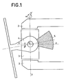
- Figure 1 shows the side view of a balancing system according to the prior art.
- the antenna unbalance is balanced using a mass 5 fixed to the attachment piece 4 on the other side of the antenna relative to the center of rotation O.
- the mass acts directly on the axis of rotation x'Ox and its volume limit the deflection of the antenna in ⁇ and ⁇ .
- FIG. 2 represents the vertical section of a preferred embodiment of the balancing system according to the invention.
- the attachment piece 4 is integral with the same axis of rotation x'Ox as a vertical pulley 6.
- the assembly formed by the antenna 1 and the pulley 6 has a plane of symmetry (A, x'Ox) orthogonal in the vertical section plane P and represented by its trace ⁇ .
- Two cables 71 and 72, sliding in a sheath 81 and 82 respectively, are fixed by means 9 at a point on the circumference of the pulley located on the axis of symmetry ⁇ and on the other side of the center of rotation 0 by compared to antenna 1.
- the sheaths 81 and 82 are fixed to the antenna support structure 3 by means 18 and 19 respectively.
- the balancing system also comprises, inside the structure box of the antenna mechanics (shown partially in 14), a balancing mass fixed by means of two rods 111 and 112 to the structure box 14.
- the point of attachment of the first head of each link 111, respectively 112, to the ground 10 is designated by the reference 151, respectively 152.
- the point of attachment of the second head of the link 111 , respectively 112, to the structure box 14 is designated by the reference 161, respectively 162.
- the link 111 is integral with a vertical half-pulley 121, respectively 122, the first attachment point 151, respectively 152 , being fixed to the periphery of the pulley 121, respectively 122, and the second attachment point 161, respectively 162, coinciding with the center of rotation of said pulley and its point of attachment to the structure box 14.
- the sheaths 81 and 82 are fixed to the fixed structure 14 by means 118 and 119 respectively.
- the cable 71, respectively 72, inside the sheath 81, respectively 82, is crossed with the other cable 72, respectively 71, under the attachment piece 4 of the antenna 1 relative to the cutting plane P of FIG. 2. It passes through the point of attachment 151, respectively 152, of the mass 10 at the head of the rod 111, respectively 112, at the circumference of which it is fixed by means 13.
- the cable 71 is arranged around the upper part of the pulley 6 and the cable 72 around the lower part of the pulley 6. After crossing, the cable 71 is found in below the cable 72 in the vertical plane of section P.
- the structure being symmetrical, the roles of the cables 71 and 72 are reversed when the airplane flies on its back.
- cables 71 and 72 are reversed when the carrier plane flies on its back.
- the balancing mass therefore has a movement identical to that of the antenna.
- the cables 71 and 72 sliding in the sheaths 81 and 82 respectively balance the antenna thanks to an opposing torque C 'equal to the unbalance torque C.
- the balancing system is independent of the direction of the acceleration, as in the case of a flight on the back for example, and the value of the acceleration since it acts both on the antenna and on the balancing masses and does not affect the equality of the unbalance couples C and antagonist C '.
- FIG. 3 represents a variant of the preferred embodiment of FIG. 2.
- the operating principle remains the same but the cables sliding inside the sheaths are replaced by a fluid connection, which makes it possible to eliminate the friction of the cables.
- 71 and 72 in their respective sheaths 81 and 82.
- the same references have been used for FIG. 3 as for FIG. 2 except for the transmission means 71, 72 and 81, 82.
- the transmission means used are hydraulic cylinders.
- the fixing means 9 of the cables 71 and 72 move at the periphery of the pulley 6 over a length of arc corresponding to the angle O, + ⁇ in the direct direction or - ⁇ in the opposite direction of the needles a watch in the direction of rotation of the plane of symmetry ( ⁇ , x'Ox) relative to the plane (x'Ox, z'Oz).
- the cables 71 and 72 act on the pistons 171 and 172.
- the pressure differences are transmitted, via the identical fluid lines 181 and 182 after the crossing of these at the level of the attachment part 4, to the pistons 191 and 192.
- the cable 71 pulls the piston 171, which pushes the piston 191 into the pipe 181 over a corresponding length, and pushes the piston 172, which pushes the piston 192 towards the inside of the pipe 182 over an identical length.
- the mass 10 is therefore displaced in an antagonistic manner by means of the rods 111 and 112 on the head (designated by its center 151, respectively 152) from which the fluid pressure transmitted by the lines 181 and 182 and the pistons 191 and 192 acts by means of cables 201 and 202 fixed to pistons 191, 192 respectively, and to heads, of center 151 and 152, of rods by means 13.
Landscapes
- Engineering & Computer Science (AREA)
- General Engineering & Computer Science (AREA)
- Physics & Mathematics (AREA)
- Acoustics & Sound (AREA)
- Aviation & Aerospace Engineering (AREA)
- Mechanical Engineering (AREA)
- Variable-Direction Aerials And Aerial Arrays (AREA)
- Details Of Aerials (AREA)
- Aerials With Secondary Devices (AREA)
Abstract
Description
- La présente invention concerne un système d'équilibrage d'un couple de balourd, son utilisation pour l'équilibrage d'une antenne de radar aéroporté et une antenne équilibrée par un tel système.
- Certains mécanismes animés d'un mouvement de rotation sont parfois soumis à des accélérations variables. Lorsqu'ils sont placés en porte-à-faux par .rapport à l'axe de rotation, il est nécessaire d'équilibrer le balourd ainsi créé.
- C'est en particulier le cas d'une antenne de radar aéroporté qui est orientable suivant trois axes orthogonaux. L'axe portant l'antenne doit loger des éléments tels que moteurs, les éléments de recopie d'angle ou joints tournants. L'antenne est donc placée en porte-à-faux complet par rapport à cet axe. Le porte-à-faux est souvent très important et peut atteindre quinze centimètres pour de grandes antennes.
- Au cours d'un virage ou d'une ressource, l'avion porteur peut imposer à l'antenne des facteurs de charge pouvant atteindre 10g. La masse de l'antenne et par conséquent le couple de balourd lorsqu'il n'est pas équilibré, se trouvent multipliés par ce facteur. Le balourd peut alors dépasser le couple moteur maximal possible.
- Dans l'art antérieur, l'équilibrage d'une pièce en rotation autour d'un axe est réalisé par des masses portées par le dispositif d'attache de la pièce mobile à l'opposé de ladite pièce par rapport à l'axe de rotation considéré. Les masses d'équilibrage peuvent constituer une gêne, que ce soit par- leur masse même qui vient s'ajouter à la masse du mécanisme en rotation, ou par leur volume qui limite l'ampleur du mouvement de rotation.
- La présente invention a pour objet un système d'équilibrage à distance d'une pièce animée d'un mouvement de rotation autour d'un axe par rapport auquel elle est en porte-à-faux et permettant de remédier aux inconvénients ci-dessus mentionnés.
- Le système déqulibrage, objet de la présente invention, est indépendant du sens et de la valeur de l'accélération que peut subir la pièce en rotation.
- Un autre objet de la présente invention est un système d'équilibrage de balourd permettant l'allègement des zones du mécanisme disposées en porte-à-faux.
- Un autre objet de la présente invention est un système d'équilibrage permettant d'améliorer la tenue vibratoire et de relever la fréquence de résonance des structures supportant la pièce en rotation.
- Un autre objet de la présente invention est un système d'équilibrage dans lequel les masses d'équilibrage sont reportées dans des zones non mobiles.
- La présente invention a pour objet un système d'équilibrage dans lequel l'amplitude du mouvement de rotation est rendue supérieure grâce à la suppression du volume des masses d'équilibrage au niveau de l'axe de rotation.
- La présente invention a pour objet un système d'équilibrage d'un couple de balourd pour un élément disposé en porte-à-faux par rapport à l'axe de rotation autour duquel il vient pivoter dans un sens ou dans un autre, caractérisé en ce que la loi de balourd est reproduite à distance et de façon antagoniste par une masse d'équilibrage à laquelle elle est communiquée par des moyens de transmission.
- La présente invention sera mieux comprise à la lecture de la description détaillée faite ci-après avec référence aux dessins ci- annexés qui représentent :
- - la figure 1, une vue latérale en coupe d'un système d'équilibrage de balourd selon l'art antérieur, appliqué à un mécanisme d'antenne ;
- - la figure 2, la vue latérale en coupe d'un mode de réalisation préférentiel du système d'équilibrage de balourd selon l'invention, appliqué à un mécanisme d'antenne ;
- - la figure 3, la vue latérale en coupe d'une variante de mode de réalisation préférentiel représenté par la figure 2.
- Les figures ci-annexées représentent l'application particulière aux antennes de radar aéroporté des systèmes d'équilibrage de balourd selon l'art antérieur et selon l'invention. Mais cette application particulière ne constitue pas un exemple limitatif d'application.
- Dans les différentes figures, les mêmes références désignent des éléments identiques ou jouant le même rôle. C'est ainsi que la référence 1 désigne l'antenne articulée entre les deux bras 2 du support d'antenne (représenté partiellement), selon trois axes orthogonaux par l'intermédiaire de deux pièces mobiles l'une par rapport à l'autre 3 et 4. La pièce d'attache 4 est solidaire de l'antenne 1. L'ensemble d'antenne 1, 2, 3, 4 et le mécanisme d'orientation lui- même ne constituant pas l'objet de l'invention ne seront pas décrits en détails.
- Les figures annexées 1, 2, 3 sont des vues latérales en coupe suivant un plan vertical P passant par le centre de rotation O. Les trois axes de rotation sont désignés par x'Ox, axe horizontal transversal représenté uniquement par sa trace 0 sur le plan P, y'Oy, axe vertical, et z'Oz, axe horizontal longitudinal.
- L'antenne 1 pivote autour du premier axe x'Ox avec un angle ±θ par rapport au plan (x'Ox, z'Oz), autour du second axe y'Oy avec un angle - α par rapport au plan (x'Ox, y'Oy) et autour du troisième axe de rotation z'Oz avec un angle ±β par rapport au plan (y'Oy, z'Oz).
- La figure 1 représente la vue latérale d'un système d'équilibrage selon l'art antérieur.
- L'équilibrage du balourd d'antenne est réalisé à l'aide d'une masse 5 fixée à la pièce d'attache 4 de l'autre côté de l'antenne par rapport au centre de rotation O. La masse agit directement sur l'axe de rotation x'Ox et son volume limite le débattement de l'antenne en θ et α.
- La figure 2 représente la coupe verticale d'un mode de réalisation préférentiel du système d'équilibrage conforme à l'invention.
- La pièce d'attache 4 est solidaire et de même axe de rotation x'Ox qu'une poulie verticale 6. L'ensemble formé par l'antenne 1 et la poulie 6 présente un plan de symétrie (A, x'Ox) orthogonal au plan vertical de coupe P et représenté par sa trace Δ.
- Deux câbles 71 et 72, coulissant dans une gaine 81 et 82 respectivement, sont fixés par des moyens 9 en un point de la circonférence de la poulie situé sur l'axe de symétrie Δ et de l'autre côté du centre de rotation 0 par rapport à l'antenne 1.
- Les gaines 81 et 82 sont fixées sur la structure support d'antenne 3 par des moyens 18 et 19 respectivement.
- Le système d'équilibrage conforme à l'invention comprend également, à l'intérieur du caisson de structure de la mécanique d'antenne (représenté partiellement en 14), une masse d'équilibrage fixée par l'intermédiaire de deux biellettes 111 et 112 au caisson de structure 14. Le point d'attache de la première tête de chaque biellette 111, respectivement 112, à la masse 10 est désigné par la référence 151, respectivement 152. Le point d'attache de la deuxième tête de la biellette 111, respectivement 112, au caisson de structure 14 est désigné par la référence 161, respectivement 162. La biellette 111, respectivement 112, est solidaire d'une demi-poulie verticale 121, respectivement 122, le premier point d'attache 151, respectivement 152, étant fixé à la périphérie de la poulie 121, respectivement 122, et le deuxième point d'attache 161, respectivement 162, coïncidant avec le centre de rotation de ladite poulie et son point de fixation au caisson de structure 14.
- Les gaines 81 et 82 sont fixées sur la structure fixe 14 par des moyens 118 et 119 respectivement.
- . Le câble 71, respectivement 72, à l'intérieur de la gaine 81, respectivement 82, est croisé avec l'autre câble 72, respectivement 71, sous la pièce d'attache 4 de l'antenne 1 par rapport au plan de coupe P de la figure 2. Il passe par le point d'attache 151, respectivement 152, de la masse 10 à la tête de la biellette 111, respectivement 112, à la circonférence de laquelle il est fixé par des moyens 13.
- Si l'on suppose que l'avion porteur vole normalement, le câble 71 est disposé autour de la partie supérieure de la poulie 6 et le câble 72 autour de la partie inférieure de la poulie 6. Après croisement, le câble 71 se retrouve en-dessous du câble 72 dans le plan vertical de coupe P. La structure étant symétrique, les rôles des câbles 71 et 72 sont inversés lorsque l'avion vole sur le dos.
- Le système fonctionne de la façon suivante :
- Dans le premier cas d'un vol normal de l'avion porteur, si le plan de symétrie (Δ, x'Ox) de l'ensemble d'antenne prend une inclinaison -0 (vers le bas) par rapport au plan (x'Ox, z'Oz), la poulie 6 tourne également d'un angle ⊖ dans le sens inverse des aiguilles d'une montre. Le câblé 72 fixé par les moyens 9 vient s'enrouler autour de la poulie sur une longueur égale à l'arc 0, en coulissant à l'intérieur de la gaine 82, alors que le câble 71 est relâché sur une longueur identique. Le câble 72 qui est donc le câble supérieur vient tirer la tête de biellette 152 et par conséquent déplace la masse 10 vers le haut. Le câble 71 accompagne et limite le mouvement puisque son point d'attache en 9 s'est déplacé d'une longueur correspondante. Inversement, si l'antenne est orientée de façon à ce que le plan de symétrie (Δ, x'Ox) fasse un angle +0 (vers le haut) par rapport au plan (x'Ox, z'Oz), la poulie 6 tourne d'un angle ⊖ dans le sens des aiguilles d'une montre. Le câble 71 fixé par les moyens 9 vient s'enrouler autour de la poulie sur une longueur égale à l'arc 0, en coulissant à l'intérieur de la gaine 81, alors que le câble 72 est relâché sur une longueur identique. Le câble 71, qui est le câble inférieur, vient tirer la tête de biellette 151 et déplace par conséquent la masse 10 vers le bas. Le câble 72 accompagne le mouvement et le limite puisque son point d'attache 9 s'est déplacé d'une longueur égale à celle du point d'attache 9 du câble 71. Il aide également à supporter la masse 10.
- Les rôles des câbles 71 et 72 sont inversés lorsque l'avion porteur vole sur le dos.
- La masse d'équilibrage a donc un mouvement identique à celui de l'antenne.
- . Lorsque l'antenne débat autour de son axe, le couple de balourd est de la forme :

- -m est la masse de l'antenne,
- - d la distance de son centre de gravité G à l'axe de rotation,
- - α l'accélération au lieu considéré,
- - 0 l'angle de débattement.
- On recrée donc le même mouvement au niveau de la masse d'équilibrage en recréant un couple antagoniste de la forme :

- - m' est la masse d'équilibrage (masse 10),
- - d' la distance du centre de gravité G' de la masse à son axe de rotation, donc la distance entre les axes de rotation 151, respectivement 152, à 161, respectivement 162, des têtes de chaque biellettes.
- Les câbles 71 et 72 coulissant dans les gaines 81 et 82 respectivement équilibrent l'antenne grâce à un couple antagoniste C' égal au couple de balourd C.
- Le système d'équilibrage est indépendant du sens de l'accélération, comme dans le cas d'un vol sur le dos par exemple, et de la valeur de l'accélération puisque celle-ci agit à la fois sur l'antenne et sur les masses d'équilibrage et n'affecte pas l'égalité des couples de balourd C et antagoniste C'.
- La figure 3 représente une variante du mode de réalisation préférentiel de la figure 2. Le principe de fonctionnement reste le même mais les câbles coulissant à l'intérieur de gaines sont remplacés par une liaison fluide, ce qui permet d'éliminer le frottement des câbles 71 et 72 dans leur gaine respective 81 et 82. Les mêmes références ont été utilisées pour la figure 3 que pour la figure 2 sauf en ce qui concerne les moyens de transmission 71, 72 et 81, 82. Les moyens de transmission utilisés sont des vérins hydrauliques. Lorsque l'antenne 1, donc la poulie 6 qui lui est solidaire, tourne d'un angle ⊖, les moyens de fixation 9 des cables 71 et 72 se déplacent à la périphérie de la poulie 6 sur une longueur d'arc correspondant à l'angle O, +⊖ dans le sens direct ou -⊖ dans le sens inverse des aiguilles d'une montre suivant le sens de la rotation du plan de symétrie (Δ, x'Ox) par rapport au plan (x'Ox, z'Oz). Les câbles 71 et 72 agissent sur les pistons 171 et 172. Les différences de pression sont transmises, par l'intermédiaire des canalisations identiques de fluide 181 et 182 après le croisement de celles-ci au niveau de la pièce d'attache 4, aux pistons 191 et 192. Dans le cas d'une rotation de +O, le câble 71 tire le piston 171, ce qui enfonce le piston 191 dans la canalisation 181 sur une longueur correspondante, et enfonce le piston 172, ce qui pousse le piston 192 vers l'intérieur de la canalisation 182 sur une longueur identique. La masse 10 est donc déplacée de façon antagoniste par l'intermédiaire des biellettes 111 et 112 sur la tête (désignée par son centre 151, respectivement 152) desquelles la pression de fluide transmise par les canalisations 181 et 182 et les pistons 191 et 192 agit par l'intermédiaire des câbles 201 et 202 fixés aux pistons 191, 192 respectivement, et aux têtes, de centre 151 et 152,de biellettes par les moyens 13.
- Lorsque la rotation est de -O, le rôle des câbles 71 et 72 ainsi que des pistons 171 et 172 est inversé.
- Les mouvements de la masse 10 et de l'antenne 1 seront toujours antagonistes comme expliqués dans la description correspondant à la figure 2 et à l'explication ci-dessus du mode de fonctionnement des moyens de transmission à distance de la loi de balourd.
- Les modes de réalisation des figures 2 et 3 ne sont pas limitatifs. Tout mode de réalisation dans lequel la loi de balourd du mécanisme placé en porte-à-faux et animé d'un mouvement de rotation autour d'un axe est reproduite à distance et de façon antagoniste ne sort pas du cadre de la présente invention.
Claims (8)
Applications Claiming Priority (2)
| Application Number | Priority Date | Filing Date | Title |
|---|---|---|---|
| FR8118137A FR2513760A1 (fr) | 1981-09-25 | 1981-09-25 | Systeme d'equilibrage d'un couple de balourd, utilisation d'un tel systeme pour une antenne de radar aeroporte et antenne equilibree par un tel systeme |
| FR8118137 | 1981-09-25 |
Publications (2)
| Publication Number | Publication Date |
|---|---|
| EP0076194A1 true EP0076194A1 (fr) | 1983-04-06 |
| EP0076194B1 EP0076194B1 (fr) | 1986-04-16 |
Family
ID=9262480
Family Applications (1)
| Application Number | Title | Priority Date | Filing Date |
|---|---|---|---|
| EP82401686A Expired EP0076194B1 (fr) | 1981-09-25 | 1982-09-16 | Système d'équilibrage d'un couple de balourd, utilisation d'un tel système pour une antenne de radar aéroporté, et antenne équilibrée par un tel système |
Country Status (4)
| Country | Link |
|---|---|
| US (1) | US4512448A (fr) |
| EP (1) | EP0076194B1 (fr) |
| DE (1) | DE3270647D1 (fr) |
| FR (1) | FR2513760A1 (fr) |
Families Citing this family (6)
| Publication number | Priority date | Publication date | Assignee | Title |
|---|---|---|---|---|
| FR2593646B1 (fr) * | 1986-01-28 | 1988-07-29 | Thomson Csf | Antenne radar a faible encombrement. |
| JPS6359513A (ja) * | 1986-08-30 | 1988-03-15 | Toyo Seikan Kaisha Ltd | ポリエステル中空成形体の製造 |
| US4779712A (en) * | 1986-09-15 | 1988-10-25 | General Electric Company | Equipoise assembly |
| FR2685081B1 (fr) * | 1991-12-11 | 1994-02-04 | Thomson Csf | Structure a controle d'endommagement intrinseque, procede de fabrication et methode d'utilisation. |
| GB0030931D0 (en) * | 2000-12-19 | 2001-01-31 | Radiant Networks Plc | Support structure for antennas, transceiver apparatus and rotary coupling |
| US11166592B2 (en) | 2017-09-25 | 2021-11-09 | Whirlpool Corporation | Food processor |
Citations (9)
| Publication number | Priority date | Publication date | Assignee | Title |
|---|---|---|---|---|
| FR321466A (fr) * | 1902-04-11 | 1903-01-10 | Bence A | Nouveau genre de contrepoids automatique pour l'équilibrage d'un mouvement alternatif commandé par un mouvement circulaire dans le cas oÙ la pose d'un contrepoids ne peut etre placée directement sur le plateau ou l'arbre manivelle de la pièce en mouvement |
| US2408825A (en) * | 1941-09-30 | 1946-10-08 | Univ Leland Stanford Junior | Object detecting and locating system |
| US3125888A (en) * | 1964-03-24 | Resonant oscillating antenna drive | ||
| FR1457506A (fr) * | 1965-08-25 | 1966-01-24 | Kaman Aircraft Corp | Isolateur de vibrations |
| GB1037794A (en) * | 1964-03-20 | 1966-08-03 | Henry Charles Husband | Improvements in and relating to support structures |
| DE1274787B (de) * | 1959-03-11 | 1968-08-08 | Fritz Hofmann Ges Mit Beschrae | Roentgenuntersuchungsgeraet |
| FR1594899A (fr) * | 1968-03-08 | 1970-06-08 | ||
| US3889551A (en) * | 1973-12-27 | 1975-06-17 | Rca Corp | Equipoise mechanism |
| FR2437538A1 (fr) * | 1978-09-29 | 1980-04-25 | Philips Nv | Dispositif a bras pivotant equilibre |
Family Cites Families (3)
| Publication number | Priority date | Publication date | Assignee | Title |
|---|---|---|---|---|
| GB592029A (en) * | 1942-05-11 | 1947-09-05 | Nash & Thompson Ltd | Improvements in and relating to scanning mechanism in which oscillating motion and rotatory motion are imparted to a member |
| US3860931A (en) * | 1973-11-26 | 1975-01-14 | Post Office | Ship-borne gravity stabilized antenna |
| US4396919A (en) * | 1981-04-06 | 1983-08-02 | General Dynamics, Pomona Division | Differential drive pedestal gimbal |
-
1981
- 1981-09-25 FR FR8118137A patent/FR2513760A1/fr active Granted
-
1982
- 1982-09-16 US US06/418,837 patent/US4512448A/en not_active Expired - Fee Related
- 1982-09-16 EP EP82401686A patent/EP0076194B1/fr not_active Expired
- 1982-09-16 DE DE8282401686T patent/DE3270647D1/de not_active Expired
Patent Citations (9)
| Publication number | Priority date | Publication date | Assignee | Title |
|---|---|---|---|---|
| US3125888A (en) * | 1964-03-24 | Resonant oscillating antenna drive | ||
| FR321466A (fr) * | 1902-04-11 | 1903-01-10 | Bence A | Nouveau genre de contrepoids automatique pour l'équilibrage d'un mouvement alternatif commandé par un mouvement circulaire dans le cas oÙ la pose d'un contrepoids ne peut etre placée directement sur le plateau ou l'arbre manivelle de la pièce en mouvement |
| US2408825A (en) * | 1941-09-30 | 1946-10-08 | Univ Leland Stanford Junior | Object detecting and locating system |
| DE1274787B (de) * | 1959-03-11 | 1968-08-08 | Fritz Hofmann Ges Mit Beschrae | Roentgenuntersuchungsgeraet |
| GB1037794A (en) * | 1964-03-20 | 1966-08-03 | Henry Charles Husband | Improvements in and relating to support structures |
| FR1457506A (fr) * | 1965-08-25 | 1966-01-24 | Kaman Aircraft Corp | Isolateur de vibrations |
| FR1594899A (fr) * | 1968-03-08 | 1970-06-08 | ||
| US3889551A (en) * | 1973-12-27 | 1975-06-17 | Rca Corp | Equipoise mechanism |
| FR2437538A1 (fr) * | 1978-09-29 | 1980-04-25 | Philips Nv | Dispositif a bras pivotant equilibre |
Also Published As
| Publication number | Publication date |
|---|---|
| EP0076194B1 (fr) | 1986-04-16 |
| US4512448A (en) | 1985-04-23 |
| DE3270647D1 (en) | 1986-05-22 |
| FR2513760B1 (fr) | 1985-02-01 |
| FR2513760A1 (fr) | 1983-04-01 |
Similar Documents
| Publication | Publication Date | Title |
|---|---|---|
| EP0362342B1 (fr) | Dispositif articule, notamment utilisable dans le domaine de la robotique | |
| FR2757440A1 (fr) | Plateforme hexapode et dispositifs d'articulation spherique utilisables pour sa realisation | |
| EP0308347A1 (fr) | Appareil manipulateur de tête de test à suspension ameliorée | |
| FR2483388A1 (fr) | Appareil a plate-forme de levage muni d'un indicateur de charge limite | |
| EP0081401A1 (fr) | Système permettant le maintien temporaire et la libération de deux parties, plus particulièrement dans le domaine spatial | |
| EP0520872B1 (fr) | Simulateur de vibrations de mât d'hélicoptère | |
| EP0076194B1 (fr) | Système d'équilibrage d'un couple de balourd, utilisation d'un tel système pour une antenne de radar aéroporté, et antenne équilibrée par un tel système | |
| FR2574189A1 (fr) | Appareil generateur de chocs pour l'exploration sismique du sous-sol | |
| FR2696013A1 (fr) | Combineur holographique escamotable, notamment pour aéronef. | |
| CA1187163A (fr) | Dispositif mixte d'emission d'ondes longitudinales ou transversales | |
| EP2231499B1 (fr) | Dispositif de levage et deplacement d'un objet comprenant une centrale inertielle | |
| EP0165129A1 (fr) | Dispositif d'équilibrage des forces de pesanteur dans un bras robotique | |
| CA2082519A1 (fr) | Systeme d'aide au pilotage d'un helicoptere portant une charge, notamment en vol stationnaire | |
| CA1133109A (fr) | Dispositif mobile pour engendrer dans le sol des ondes acoustiques transversales | |
| EP0101331A2 (fr) | Dispositif perfectionné pour engendrer dans le sol des ondes acoustiques transversales | |
| EP0165877B1 (fr) | Dispositif goniométrique pour diffractométrie de rayons X ou de neutrons sur des monocristaux | |
| FR2653219A1 (fr) | Detecteur et procede de detection de verticalite, et base de maintien d'attitude d'un appareil. | |
| EP0056550A2 (fr) | Dispositif d'orientation selon deux axes orthogonaux, en particulier pour une antenne hyperfréquence | |
| FR2880575A1 (fr) | Robot parallele incluant des moyens de compensation de charge | |
| WO1988005108A1 (fr) | Sonde et son dispositif d'ancrage multidirectionnel dans un puits | |
| FR2714855A1 (fr) | Vibreur à faible encombrement et à grande force de vibration, et machines équipées de ce vibreur. | |
| FR2541770A1 (fr) | Generateur de force electromagnetique et resonnant pour machines d'essais de fatigue et de fissuration par fatigue des materiaux | |
| FR2467169A1 (fr) | Grue a tour | |
| EP0802144A1 (fr) | Dispositif pour saisir et manipuler des charges | |
| FR2608779A1 (fr) | Dispositif perfectionne pour engendrer dans le sol a la fois des ondes acoustiques transversales et longitudinales suivant une pluralite de directions differentes |
Legal Events
| Date | Code | Title | Description |
|---|---|---|---|
| PUAI | Public reference made under article 153(3) epc to a published international application that has entered the european phase |
Free format text: ORIGINAL CODE: 0009012 |
|
| AK | Designated contracting states |
Designated state(s): DE GB IT |
|
| 17P | Request for examination filed |
Effective date: 19830827 |
|
| GRAA | (expected) grant |
Free format text: ORIGINAL CODE: 0009210 |
|
| AK | Designated contracting states |
Kind code of ref document: B1 Designated state(s): DE GB IT |
|
| ITF | It: translation for a ep patent filed | ||
| REF | Corresponds to: |
Ref document number: 3270647 Country of ref document: DE Date of ref document: 19860522 |
|
| PLBE | No opposition filed within time limit |
Free format text: ORIGINAL CODE: 0009261 |
|
| STAA | Information on the status of an ep patent application or granted ep patent |
Free format text: STATUS: NO OPPOSITION FILED WITHIN TIME LIMIT |
|
| 26N | No opposition filed | ||
| PGFP | Annual fee paid to national office [announced via postgrant information from national office to epo] |
Ref country code: DE Payment date: 19910802 Year of fee payment: 10 |
|
| PGFP | Annual fee paid to national office [announced via postgrant information from national office to epo] |
Ref country code: GB Payment date: 19910807 Year of fee payment: 10 |
|
| ITTA | It: last paid annual fee | ||
| PG25 | Lapsed in a contracting state [announced via postgrant information from national office to epo] |
Ref country code: GB Effective date: 19920916 |
|
| GBPC | Gb: european patent ceased through non-payment of renewal fee |
Effective date: 19920916 |
|
| PG25 | Lapsed in a contracting state [announced via postgrant information from national office to epo] |
Ref country code: DE Effective date: 19930602 |