EP0076232B1 - Procédé et appareil de mesure électro-optique de la distance - Google Patents
Procédé et appareil de mesure électro-optique de la distance Download PDFInfo
- Publication number
- EP0076232B1 EP0076232B1 EP82810375A EP82810375A EP0076232B1 EP 0076232 B1 EP0076232 B1 EP 0076232B1 EP 82810375 A EP82810375 A EP 82810375A EP 82810375 A EP82810375 A EP 82810375A EP 0076232 B1 EP0076232 B1 EP 0076232B1
- Authority
- EP
- European Patent Office
- Prior art keywords
- pulses
- signal
- signals
- gating
- duration
- Prior art date
- Legal status (The legal status is an assumption and is not a legal conclusion. Google has not performed a legal analysis and makes no representation as to the accuracy of the status listed.)
- Expired
Links
- 238000000034 method Methods 0.000 title claims description 14
- 238000005259 measurement Methods 0.000 claims description 35
- 230000005540 biological transmission Effects 0.000 claims description 13
- 230000002045 lasting effect Effects 0.000 claims description 3
- 230000000737 periodic effect Effects 0.000 claims description 2
- 230000003247 decreasing effect Effects 0.000 claims 2
- 230000000875 corresponding effect Effects 0.000 description 12
- 230000001960 triggered effect Effects 0.000 description 9
- 238000012935 Averaging Methods 0.000 description 4
- 238000006243 chemical reaction Methods 0.000 description 4
- 230000003287 optical effect Effects 0.000 description 4
- 230000015572 biosynthetic process Effects 0.000 description 3
- 230000000903 blocking effect Effects 0.000 description 3
- 238000011156 evaluation Methods 0.000 description 3
- 239000010437 gem Substances 0.000 description 3
- 239000010453 quartz Substances 0.000 description 3
- 230000035945 sensitivity Effects 0.000 description 3
- VYPSYNLAJGMNEJ-UHFFFAOYSA-N silicon dioxide Inorganic materials O=[Si]=O VYPSYNLAJGMNEJ-UHFFFAOYSA-N 0.000 description 3
- 230000001629 suppression Effects 0.000 description 3
- 238000012937 correction Methods 0.000 description 2
- 230000002596 correlated effect Effects 0.000 description 2
- 238000010586 diagram Methods 0.000 description 2
- 238000013213 extrapolation Methods 0.000 description 2
- 239000013307 optical fiber Substances 0.000 description 2
- 238000002360 preparation method Methods 0.000 description 2
- 230000009897 systematic effect Effects 0.000 description 2
- 238000012360 testing method Methods 0.000 description 2
- 239000000654 additive Substances 0.000 description 1
- 230000000996 additive effect Effects 0.000 description 1
- 230000015556 catabolic process Effects 0.000 description 1
- 230000001419 dependent effect Effects 0.000 description 1
- 238000001514 detection method Methods 0.000 description 1
- 238000002592 echocardiography Methods 0.000 description 1
- 230000000694 effects Effects 0.000 description 1
- 239000011888 foil Substances 0.000 description 1
- 238000000265 homogenisation Methods 0.000 description 1
- 239000004973 liquid crystal related substance Substances 0.000 description 1
- 230000000873 masking effect Effects 0.000 description 1
- 230000011514 reflex Effects 0.000 description 1
- 230000001105 regulatory effect Effects 0.000 description 1
- 230000004044 response Effects 0.000 description 1
- 230000000630 rising effect Effects 0.000 description 1
- 238000007493 shaping process Methods 0.000 description 1
- 238000012546 transfer Methods 0.000 description 1
Images

Classifications
-
- G—PHYSICS
- G01—MEASURING; TESTING
- G01S—RADIO DIRECTION-FINDING; RADIO NAVIGATION; DETERMINING DISTANCE OR VELOCITY BY USE OF RADIO WAVES; LOCATING OR PRESENCE-DETECTING BY USE OF THE REFLECTION OR RERADIATION OF RADIO WAVES; ANALOGOUS ARRANGEMENTS USING OTHER WAVES
- G01S7/00—Details of systems according to groups G01S13/00, G01S15/00, G01S17/00
- G01S7/48—Details of systems according to groups G01S13/00, G01S15/00, G01S17/00 of systems according to group G01S17/00
- G01S7/497—Means for monitoring or calibrating
-
- G—PHYSICS
- G01—MEASURING; TESTING
- G01S—RADIO DIRECTION-FINDING; RADIO NAVIGATION; DETERMINING DISTANCE OR VELOCITY BY USE OF RADIO WAVES; LOCATING OR PRESENCE-DETECTING BY USE OF THE REFLECTION OR RERADIATION OF RADIO WAVES; ANALOGOUS ARRANGEMENTS USING OTHER WAVES
- G01S17/00—Systems using the reflection or reradiation of electromagnetic waves other than radio waves, e.g. lidar systems
- G01S17/02—Systems using the reflection of electromagnetic waves other than radio waves
- G01S17/06—Systems determining position data of a target
- G01S17/08—Systems determining position data of a target for measuring distance only
- G01S17/10—Systems determining position data of a target for measuring distance only using transmission of interrupted, pulse-modulated waves
- G01S17/14—Systems determining position data of a target for measuring distance only using transmission of interrupted, pulse-modulated waves wherein a voltage or current pulse is initiated and terminated in accordance with the pulse transmission and echo reception respectively, e.g. using counters
-
- G—PHYSICS
- G04—HOROLOGY
- G04F—TIME-INTERVAL MEASURING
- G04F10/00—Apparatus for measuring unknown time intervals by electric means
-
- G—PHYSICS
- G04—HOROLOGY
- G04F—TIME-INTERVAL MEASURING
- G04F10/00—Apparatus for measuring unknown time intervals by electric means
- G04F10/04—Apparatus for measuring unknown time intervals by electric means by counting pulses or half-cycles of an AC
Definitions
- the invention relates to a method for measuring the distance between an object and a reference point, in which a plurality of light pulses are successively transmitted from a transmitter arranged at the reference point to the object and from the object back to a receiving device in the vicinity of the transmitter and in which it is obtained the duration of the light pulses are generated by means of a photoelectric receiver, transmission and reception times of the light pulses defining electrical signal pulses and by means of a gate signal circuit between them permanent gate signals and the duration of each gate signal is determined by counting the clock pulses of a clock oscillator in a counter controlled by the gate signal circuit, and a distance measuring device for carrying it out.
- Electro-optical distance measuring devices are known, for example from CH-PS551 628 and from General. Verresssnachzin, 80th year, issue 6/1973, pp. 201-207.
- the light signals are given by a continuous, 15 MHz amplitude-modulated infrared light source, and the phase difference between transmitted and received modulation is determined as the time difference.
- electronic circuits for frequency conversion and for digital phase measurement are used. To increase the measurement accuracy, simply count a large number (e.g. 300,000) of successive modulation periods and calculate the measurement result by arithmetic averaging.
- target reflectors can be dispensed with, but the sensitivity to incorrect measurements due to reflection disturbances, incorrect aiming, multiple echoes, etc. is greater. than in systems of the first-mentioned type.
- light receivers with controllable masking means are known which only enable reception during a time window which corresponds to a limited distance measuring range.
- controllable masking means are known which only enable reception during a time window which corresponds to a limited distance measuring range.
- such known means primarily serve to protect the light receiver from damage due to excessive exposure and only to increase the measurement accuracy.
- a digital circuit is known from DE-AS 2 420194 which determines the statistical variance of the phase difference values, compares them with an internal test limit value and only releases a display of the measurement result, if the variance does not exceed the test limit.
- all individual measured values contribute to the formation of the variance and the measurement result, that is to say also those which, because of reflection disturbances, do not allow any information about the measuring distance.
- a counter circuit for the time difference between two successive electrical pulse signals is known from US-A-3 325 750 (General Electric Comp.).
- the counting cycle starts with the frequency f 1 and with the stop pulse, the counting cycle starts with the frequency f 2 , whereby f 1 continues until a coincidence between f 1 and f 2 occurs.
- the time difference is the sum of the periods counted with f 1 plus the periods counted with f 2 .
- the object of the present invention is to provide a method and a device for electro-optical distance measurement, which allows measurement also on non-cooperative targets, as well as increased measurement accuracy, and in which only those individual measured values for distance formation are evaluated which with a certain probability are not distorted by reflection disorders.
- this object is achieved in that for each of at least two threshold values there are in each case a multiplicity of, during the time between the occurrence of these threshold values on respective edges Transmitting and receiving time of a signal pulse defining signal pulses lasting gate signals is generated and the counting results corresponding to these gate signals are registered so that the clock oscillator is operated in such a way that the switching times of the gate circuit are not correlated with the pulses of the clock oscillator that by the weighted average of the three count results with the greatest, second largest and third largest frequency for each threshold value determines the gate signal duration and determines the duration corresponding to the running time of the light pulses from the dependence of the gate signal duration thus determined on the threshold value mt which is assigned to the searched distance.
- the window signals after switching off the light pulses from a periodic sequence of auxiliary pulses provide two varieties of a pair of transmission and reception times a signal pulse simulating light pulses can be selected to generate the gate signals, wherein the ratio of the time intervals between the signal pulses per one of the pairs is known and not equal to one, and that the constant error in the counting of the time duration of each gate signal is calculated by linear combination of the time periods determined for the signal pulse pairs.
- the duration of the light pulses corresponding to the distance sought is advantageously determined from the dependence of the determined gate signal duration on the threshold value such that a first threshold value in the order of magnitude of the maximum occurring noise level of the photoelectric receiver for the light pulses is determined by changing the operating point of the receiver for the light pulses whose noise level is set in such a way that the frequency of incorrect measurements of the pulse transit times triggered by noise pulses is below a predetermined level, that a gate signal duration corresponding to the first threshold value is then determined, that approximately twice the first threshold value is selected as a second threshold value and a second gate signal duration is determined for this second threshold value and that from the two pairs of values a linear signal extrapolation determines a gate signal duration corresponding to a threshold value zero as the transit time of the light pulses becomes.
- the transit time is expediently determined from the first gate signal duration by adding a fixed correction value.
- Devices for generating start signals for emitting the light pulses devices for generating a number of different threshold values each determining a response threshold of the gate signal circuit for the signal pulses of the receiver,
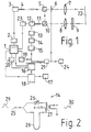
- the emitting of the light pulses is stimulated by current pulses which a driver stage 2 generates after being triggered by a start signal from a processor stage 1 .
- the laser diode 3 is connected to a short optical fiber 4, through which the light pulses pass for homogenization.
- the laser diode 3 is followed by a light splitter prism 5, which branches off about 1% of the optical power of the light pulses.
- the light pulses pass through a liquid crystal attenuator 6, an optical transmitter 7 and the actual measuring path up to an object 22 at the other end of the measuring path.
- this object can be a mirror or a combination of mirrors (cube corner, reflector foil), or a non-cooperative measurement object (tree, wall, vehicle) that scatters part of the light pulses back to the transmitter.
- the backscattered part of the light pulses passes through a narrow-band color filter 9 to reduce ambient light, which also penetrates, and a receiver optics 8 onto a second light splitter prism 10, which re-introduces about 1% of the optical power of the pulses branched off in the prism 5 into the main beam path as short-path signals.
- Short-path pulses and measuring-path pulses arrive at an avalanche photodiode 12 with a short optical fiber 11 placed in front for the photoelectric conversion.
- the operating point of the diode 12 is set by means of the regulated bias voltage via a supply voltage stage 23 controlled by the processor stage 1.
- a preamplifier 13 is provided.
- a pulse shaper stage 14 is useful for optimizing the pulse edges. After passing through stages 13 and 14, the pulses are amplified again in an amplifier 15 and then arrive at a comparator stage 16, to which an adjustable threshold signal is fed by processor 1.
- the short-path pulse branched off at prism 5 and the measuring path pulse as assigned signal pulses have a time offset from which the length of the measuring section is to be determined.
- the short-path signal acts as a start pulse for generating a gate signal, which is ended as a stop pulse by the assigned measuring path pulse and therefore continues during the said time offset.
- a counter 18 for counting the positive edges of a quartz oscillator 17 as a time standard (clock oscillator) is scanned by this gate signal. If the frequency of the oscillator 17 is 150 MHz, then a pulse counted in the counter 18 corresponds precisely to a 1 m step of the measuring distance.
- the counting result in meter steps is transferred to processor 1 and stored there in table form, while a new pulse is triggered at laser diode 3 via driver stage 2.
- the amplifier 15 is followed by a signal control stage 21 with a display device 24.
- the control stage 21 comprises a selection logic which is controlled by the processor 1 by means of a window signal.
- This window signal of adjustable length suppresses any interference pulses present on the laser diode 3 for a certain time.
- the duration (length) of the window signal is output in code form by the processor 1 to a window circuit 20 which generates the window signal as a rectangle when the laser pulse is triggered and turns it on the comparator stage 16 and the signal control stage 21 outputs.
- a 5 MHz square wave oscillator 19 is provided for determining an addition constant for the transit time measurement that is dependent on the threshold value, the pulses of which are input from the amplifier 15 into the comparator 16 instead of the start-stop pulses and, as described in more detail below, be evaluated.
- FIG. 2 shows an embodiment of the pulse shaper stage 14 for optimizing the pulse edges of the received signals.
- the signals are divided at input 25.
- One component runs via an attenuator 26 directly to a hybrid T-divider 27, the other component runs via a delay line 28 to the divider 27. Both components are thus shifted against each other and reassembled with opposite signs.
- this pulse shaping stage 14 results in a higher pulse edge, which facilitates the measurement in the case of strongly rounded and weak signals.
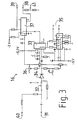
- Fig. 3 shows a circuit for the comparator stage 16.
- the start and stop signals from the amplifier 15 reach the input 31 and can be switched with a switch 32 either to the signal control stage 21 for the signal strength display or to a fast threshold switch 33.
- the signals are expediently limited to approximately 50 mV by a biased diode 34 inserted between switch 32 and threshold switch 33.
- a second input 35 four different threshold values can be set on the threshold switch 33 by a binary-coded signal from the processor 1.
- the level of these threshold values can be varied with a potentiometer 36.
- the output signals of the threshold switch 33 switch a fast bistable switch 37 only when it is prepared by a window signal fed in at a third input 39 from the window circuit 20.
- the gate signal is generated at the output 38 of the switch 37, the duration of which is to be determined. If the bistable switch 37 prepared by the window signal (43 in FIG. 4) was triggered by the start signal (45 in FIG. 4), stop signals (49 in FIG. 4) can only bring the switch 37 back over when no window signal is present. The blocking effect for the stop signals therefore only begins after the switching effect by the start signal. Measuring points 40 and 41 are provided for checking the input and output signals.
- the gate signal reaches a preparation input of the counter 18, so that it can be counted asynchronously by the positive edges of the quartz oscillator 17.
- the counter 18 has a reset unit so that it can be reset to 0 after the counting result has been output. If the gate time is longer than a maximum value (eg 54.6 ⁇ sec corresponding to a measuring distance 8 192 m), the counter 18 generates an overflow pulse which is transmitted to the comparator stage 16 as Stop signal is coupled. This is particularly useful at low levels of the received laser pulses, because these may get lost as stop signals.
- the overflow pulse is also transmitted to the processor 1 so that the next measurement can take place.
- the signals from oscillator 17, comparator 16 and the window signal of stage 20 must not be correlated with one another, so that no systematic counting errors but only random counting errors can occur. Therefore, two or even three neighboring values can be counted for a given duration of the gate signal.
- the intermediate value of the measuring distance is calculated from the frequency distribution of the three most frequent counting results by weighted averaging. The interpolation accuracy increases with the root of the number of counts. It results from 10,000 counts of ⁇ 0.5 cm.
- the window signal has an essential purpose for determining the electrical addition constants occurring in the comparator stage 16. So that the counter 18 can count the length of the gate signal supplied by the comparator 16 with the pulses from the 150 MHz oscillator 17 with sufficient accuracy (1.5 cm distance error corresponds to 100 psec gate signal error), the edges of the gate signal must be optimal. If this is the case, there are nevertheless differences in the measured times with edge steepnesses of 1 to 2 nsec as a result of a different decision behavior of the counter for falling and rising edges of its preparation signal.
- the resulting error in the runtime measurement is an additive constant under constant operating conditions (supply voltage, temperature). This constant is measured by the following method and used to correct the time measurement.
- the 5 MHz rectangular oscillator 19 generates auxiliary pulses of the same shape as the start and stop signals at the output of the amplifier 15. These pulses are entered at the input 31 of the comparator 16 instead of the start-stop signals, the light pulse generation at the laser diode 3 being interrupted. If one now selects the duration of the window signal entered at the input 39 of the comparator 16 such that reflections from measuring distances between 0 and 30 m are ineffective, then a positive auxiliary pulse edge always falls into the blocking window and the next positive edge behind the blocking window, the phase position between the auxiliary signals and the window signals can be arbitrary. Accordingly, the distance 30 m corresponding to the time interval between successive positive auxiliary pulse edges (200 nsec) is measured, increased by the addition constant C.
- a positive auxiliary pulse edge always acts as a start pulse and the next but one positive edge acts as a stop pulse.
- the distance between the supplied auxiliary pulses 200 nsec
- the distance 60 m is now measured, increased by the addition constant C.
- the addition constant C then simply results from the difference in the measurement results:
- the auxiliary pulses from the oscillator 19 itself are used for this purpose.
- the distances 30 m + C and 60 m + C are expediently measured, as described above for FIG. 1, by averaging from 10,000 counting results in each case.
- the edges of the gate signal can represent a source of error for the distance measurement. This is because the receiver diode 12 converts changes in amplitude of the received laser pulses into changes in the shape of their electrical output pulses. Such errors are now reduced by taking measurements with different threshold values at the input 35 of the threshold switch 33 of the comparator stage 16 (FIG. 3).
- a first threshold value in the order of magnitude of the maximum noise level of the avalanche photodiode 12 is expediently set.
- the noise level is reduced to such an extent that the frequency of the incorrect measurements triggered by noise pulses as described above in connection with the window signal for noise suppression is below a fixed limit (e.g. 50%).
- a first distance is measured, as described in detail above. Then with a second, larger threshold, z. B. measured equal to twice the first threshold a second distance. From these two measurements, a distance assigned to a zero threshold value is determined by linear extrapolation. Although an idealized linear course of the optical and electrical pulse edges is assumed, it has been shown that reliable distance values can be obtained by the measuring method according to the invention described.
- the distance corresponding to the zero threshold is obtained by adding an empirical value to the initially measured first distance.
- FIG. 4 summarizes the measurement signals occurring in the electro-optical distance measuring device according to FIG. 1 described as an example, as well as their chronological sequence over the horizontal time axis.
- the measurement begins with a start signal 42 output by processor stage 1. Before each start signal, stage 1 transmits the length of the window signal for noise suppression and the size of the threshold value to comparator stage 16 via stage 20.
- the window signal 43 begins with the start signal 42. With a small delay, the light pulse 44 is triggered on the laser diode 3 via the driver stage 2. Almost simultaneously, the short-path pulse 45 reaches the receiver diode 12 via the prisms 5 and 10 and, after opto-electrical conversion in the comparator 16, triggers the start of the gate time signal 46.
- stage 1 emits a signal 50 which resets the counter 18 to 0.
- Variants of the described exemplary embodiment according to the invention that are not described in detail, such as meteorological corrections of the measurement result, meter-foot conversion, automatic interruption in the case of a weak reflex, automatically continuous measurement with a moving target, computer-compatible result output etc. are available to the person skilled in the art according to the prior art and can be provided in the present invention.
Landscapes
- Physics & Mathematics (AREA)
- Engineering & Computer Science (AREA)
- General Physics & Mathematics (AREA)
- Electromagnetism (AREA)
- Computer Networks & Wireless Communication (AREA)
- Radar, Positioning & Navigation (AREA)
- Remote Sensing (AREA)
- Power Engineering (AREA)
- Optical Radar Systems And Details Thereof (AREA)
Claims (7)
Applications Claiming Priority (2)
| Application Number | Priority Date | Filing Date | Title |
|---|---|---|---|
| CH6249/81 | 1981-09-29 | ||
| CH6249/81A CH662187A5 (de) | 1981-09-29 | 1981-09-29 | Verfahren zur elektrooptischen distanzmessung, sowie distanzmessgeraet zur durchfuehrung des verfahrens. |
Publications (3)
| Publication Number | Publication Date |
|---|---|
| EP0076232A2 EP0076232A2 (fr) | 1983-04-06 |
| EP0076232A3 EP0076232A3 (en) | 1983-10-05 |
| EP0076232B1 true EP0076232B1 (fr) | 1987-03-04 |
Family
ID=4306607
Family Applications (1)
| Application Number | Title | Priority Date | Filing Date |
|---|---|---|---|
| EP82810375A Expired EP0076232B1 (fr) | 1981-09-29 | 1982-09-08 | Procédé et appareil de mesure électro-optique de la distance |
Country Status (4)
| Country | Link |
|---|---|
| US (1) | US4553836A (fr) |
| EP (1) | EP0076232B1 (fr) |
| CH (1) | CH662187A5 (fr) |
| DE (1) | DE3275590D1 (fr) |
Families Citing this family (26)
| Publication number | Priority date | Publication date | Assignee | Title |
|---|---|---|---|---|
| DE3411540A1 (de) * | 1984-03-29 | 1985-10-10 | Fried. Krupp Gmbh, 4300 Essen | Verfahren und vorrichtung zur ermittlung des foerdergutmengenstromes von bandfoerderern |
| DE3419117C2 (de) * | 1984-05-23 | 1986-09-04 | Rheometron AG, Basel | Optoelektrisches Entfernungsmeßgerät mit einem Zeitdiskriminator zur genauen Ermittlung der Zeitfolge elektrischer Impulse |
| DE3419320C2 (de) * | 1984-05-24 | 1986-09-11 | Rheometron AG, Basel | Optoelektrisches Entfernungsmeßgerät mit einer optischen Meßsonde |
| CH670896A5 (fr) * | 1986-08-13 | 1989-07-14 | Zellweger Uster Ag | |
| DE3640890A1 (de) * | 1986-11-29 | 1988-06-09 | Messerschmitt Boelkow Blohm | Optronische messeinrichtung zur messung der relativgeschwindigkeit |
| US4902125A (en) * | 1988-06-30 | 1990-02-20 | Raytheon Company | Optical system having beam amplification |
| US5013917A (en) * | 1988-07-07 | 1991-05-07 | Kaman Aerospace Corporation | Imaging lidar system using non-visible light |
| DE3922572C1 (fr) * | 1989-07-08 | 1990-09-13 | Messerschmitt-Boelkow-Blohm Gmbh, 8012 Ottobrunn, De | |
| US5606534A (en) | 1989-09-01 | 1997-02-25 | Quantronix, Inc. | Laser-based dimensioning system |
| FR2675907B1 (fr) * | 1991-04-29 | 1993-11-19 | Alcatel Alsthom Cie Gle Electric | Systeme de mesure de distances a echo avec dispositif de calibration. |
| US7655895B2 (en) * | 1992-05-05 | 2010-02-02 | Automotive Technologies International, Inc. | Vehicle-mounted monitoring arrangement and method using light-regulation |
| US5430537A (en) * | 1993-09-03 | 1995-07-04 | Dynamics Research Corporation | Light beam distance encoder |
| WO1995030879A1 (fr) * | 1994-05-09 | 1995-11-16 | Hines Robin H | Systeme et appareil portatif utilises pour mesurer des distances |
| US5691808A (en) * | 1995-07-31 | 1997-11-25 | Hughes Electronics | Laser range finder receiver |
| US5898484A (en) * | 1997-05-30 | 1999-04-27 | Harris; Steven E. | Hand-held distance-measurement device with an enhanced viewfinder |
| JPH1184003A (ja) * | 1997-09-04 | 1999-03-26 | Nikon Corp | 光波測距装置 |
| JP4328917B2 (ja) * | 1998-11-27 | 2009-09-09 | 株式会社トプコン | 光波距離計 |
| FR2788142B1 (fr) * | 1998-12-30 | 2001-02-02 | Commissariat Energie Atomique | Procede de mesure de duree et dispositif pour mettre en oeuvre le procede |
| EP1102041A1 (fr) * | 1999-11-20 | 2001-05-23 | Reto T. Meili | Procédé de mesure et système pour la mise en oeuvre du procédé |
| DE10025968A1 (de) * | 2000-05-25 | 2001-07-12 | Daimler Chrysler Ag | Verfahren und Schaltungsanordnung zur Entfernungsmessung nach dem Echolaufzeitprinzip |
| US6624899B1 (en) * | 2000-06-29 | 2003-09-23 | Schmitt Measurement Systems, Inc. | Triangulation displacement sensor |
| DE10112833C1 (de) * | 2001-03-16 | 2003-03-13 | Hilti Ag | Verfahren und Einrichtung zur elektrooptischen Distanzmessung |
| DE102004060622B4 (de) * | 2004-12-16 | 2015-01-22 | Hilti Aktiengesellschaft | Impuls-Laserdistanzhandmessgerät |
| WO2020168489A1 (fr) * | 2019-02-20 | 2020-08-27 | 深圳市大疆创新科技有限公司 | Appareil et procédé de télémétrie ainsi que plate-forme mobile |
| WO2023123084A1 (fr) * | 2021-12-29 | 2023-07-06 | 深圳市大疆创新科技有限公司 | Procédé de mesure de distance, dispositif de mesure de distance et plateforme mobile |
| CN120740559B (zh) * | 2025-09-01 | 2025-11-11 | 中铁一局集团有限公司 | 一种管柱施工用钢管柱垂直度测量方法及系统 |
Citations (2)
| Publication number | Priority date | Publication date | Assignee | Title |
|---|---|---|---|---|
| DE2840605A1 (de) * | 1977-09-23 | 1979-04-05 | Cilas | Laser-entfernungsmesser |
| DE2420194B2 (de) * | 1973-05-09 | 1979-08-30 | Hewlett-Packard Co., Palo Alto, Calif. (V.St.A.) | Elektro-optisches Entfernungsmeßgerät mit Mittelung der Phasendifferenzwerte |
Family Cites Families (11)
| Publication number | Priority date | Publication date | Assignee | Title |
|---|---|---|---|---|
| US3325750A (en) * | 1963-12-23 | 1967-06-13 | Gen Electric | High resolution time interval measuring circuit employing a balanced crystal oscillator |
| US3503680A (en) * | 1967-03-31 | 1970-03-31 | Perkin Elmer Corp | Range measuring system |
| US3645624A (en) * | 1970-07-07 | 1972-02-29 | Perkin Elmer Corp | Range-measuring method and apparatus |
| US3869207A (en) * | 1972-01-20 | 1975-03-04 | Comp Generale Electricite | Laser telemeter |
| DE2553691C2 (de) * | 1975-11-28 | 1986-10-30 | MITEC Moderne Industrietechnik GmbH, 8012 Ottobrunn | Verfahren zur opto-elektronischen Messung der Entfernung zwischen einem Meß- und einem Zielpunkt und Entfernungsmeßgerät zur Durchführung dieses Verfahrens |
| US3900261A (en) * | 1974-03-18 | 1975-08-19 | Transitek Corp | Electronic range finder |
| US4074264A (en) * | 1976-01-07 | 1978-02-14 | Hughes Aircraft Company | Adaptive threshold clutter processor |
| US4070673A (en) * | 1976-09-03 | 1978-01-24 | Sperry Rand Corporation | Radar video digital processor |
| US4067013A (en) * | 1976-11-12 | 1978-01-03 | The United States Of America As Represented By The Navy | Automatic thresholding and reference circuit |
| CH634419A5 (de) * | 1978-10-11 | 1983-01-31 | Kern & Co Ag | Verfahren zur elektrooptischen distanzmessung, sowie vorrichtung zur durchfuehrung des verfahrens. |
| US4308537A (en) * | 1980-05-27 | 1981-12-29 | The United States Of America As Represented By The Secretary Of The Army | Automatic range containment system |
-
1981
- 1981-09-29 CH CH6249/81A patent/CH662187A5/de not_active IP Right Cessation
-
1982
- 1982-08-30 US US06/412,496 patent/US4553836A/en not_active Expired - Fee Related
- 1982-09-08 DE DE8282810375T patent/DE3275590D1/de not_active Expired
- 1982-09-08 EP EP82810375A patent/EP0076232B1/fr not_active Expired
Patent Citations (2)
| Publication number | Priority date | Publication date | Assignee | Title |
|---|---|---|---|---|
| DE2420194B2 (de) * | 1973-05-09 | 1979-08-30 | Hewlett-Packard Co., Palo Alto, Calif. (V.St.A.) | Elektro-optisches Entfernungsmeßgerät mit Mittelung der Phasendifferenzwerte |
| DE2840605A1 (de) * | 1977-09-23 | 1979-04-05 | Cilas | Laser-entfernungsmesser |
Also Published As
| Publication number | Publication date |
|---|---|
| CH662187A5 (de) | 1987-09-15 |
| EP0076232A2 (fr) | 1983-04-06 |
| US4553836A (en) | 1985-11-19 |
| DE3275590D1 (en) | 1987-04-09 |
| EP0076232A3 (en) | 1983-10-05 |
Similar Documents
| Publication | Publication Date | Title |
|---|---|---|
| EP0076232B1 (fr) | Procédé et appareil de mesure électro-optique de la distance | |
| DE60225430T2 (de) | Entfernungsfinder, entfernungsfindeverfahren und photoelektrische wandlerschaltung | |
| DE3219423C2 (de) | Entfernungsmeßverfahren und Vorrichtung zu seiner Durchführung | |
| DE10201670B4 (de) | Zeitmesssystem und ein damit verbundenes Abstandsmesssystem | |
| DE69627488T2 (de) | Lichtstrahlentfernungsmesser | |
| EP2315045B1 (fr) | Mesure des éloignements ou des modifications d'éloignement | |
| EP0742450B1 (fr) | Procédé et dispositif de mesure du temps de vol de lumière le long d'une trajectoire de mesure entre un dispositif de mesure et un objet réfléchissant | |
| DE3640449C1 (de) | Einrichtung zum Bestimmen der Entfernung zwischen zwei Objekten,insbesondere zwei Kraftfahrzeugen | |
| EP3557286B1 (fr) | Capteur optoélectronique et procédé de détection et de détermination de distance d'un objet | |
| EP1423731A2 (fr) | Procede et dispositif pour acquerir une image telemetrique tridimensionnelle | |
| EP0099500A1 (fr) | Dispositif à mesure de la période d'impulsions | |
| DE10232878B4 (de) | Vorrichtung und Verfahren zur Distanzmessung | |
| DE2923963B1 (de) | Verfahren zur Impulsabstandsmessung und Anordnung zur Durchfuehrung des Verfahrens | |
| EP0173087A1 (fr) | Dispositif pour mesurer le temps de parcours d'ondes électromagnétiques | |
| DE10022054B4 (de) | Optischer Distanzsensor | |
| EP0312524B1 (fr) | Procede et installation pour mesurer une distance par le traitement d'un signal optique a impulsions | |
| CH670895A5 (fr) | ||
| DE10153742A1 (de) | Verfahren und Vorrichtung zur Aufnahme eines dreidimensionalen Abstandsbildes | |
| DE202014007924U9 (de) | Sensor mit Hintergrundausblendung | |
| DE2257445B2 (de) | Visuell ausrichtbarer elektrooptischer laufzeit-entfernungsmesser mit intensitaetssteuerung | |
| DE1201428B (de) | UEberwachungs- und Alarmeinrichtung fuer nach dem Rueckstrahlprinzip mit kontinuierlichen, frequenzmodulierten Wellen arbeitende Hoehenmesser | |
| DE102004031024B4 (de) | Optischer Sensor | |
| DE10346813A1 (de) | Optoelektronischer Sensor und Verfahren zur Detektion eines Objekts in einem Überwachungbereich | |
| DE1935012C3 (de) | FM-CW-Höhenmesser mit Dreieckmodulation und einem Bezugsempfänger | |
| DE10138531A1 (de) | Verfahren und Vorrichtung zur Aufnahme eines dreidimensionalen Abstandsbildes |
Legal Events
| Date | Code | Title | Description |
|---|---|---|---|
| PUAI | Public reference made under article 153(3) epc to a published international application that has entered the european phase |
Free format text: ORIGINAL CODE: 0009012 |
|
| AK | Designated contracting states |
Designated state(s): DE GB SE |
|
| PUAL | Search report despatched |
Free format text: ORIGINAL CODE: 0009013 |
|
| AK | Designated contracting states |
Designated state(s): DE GB SE |
|
| 17P | Request for examination filed |
Effective date: 19831114 |
|
| GRAA | (expected) grant |
Free format text: ORIGINAL CODE: 0009210 |
|
| AK | Designated contracting states |
Kind code of ref document: B1 Designated state(s): DE GB SE |
|
| REF | Corresponds to: |
Ref document number: 3275590 Country of ref document: DE Date of ref document: 19870409 |
|
| PLBE | No opposition filed within time limit |
Free format text: ORIGINAL CODE: 0009261 |
|
| STAA | Information on the status of an ep patent application or granted ep patent |
Free format text: STATUS: NO OPPOSITION FILED WITHIN TIME LIMIT |
|
| 26N | No opposition filed | ||
| PGFP | Annual fee paid to national office [announced via postgrant information from national office to epo] |
Ref country code: GB Payment date: 19910808 Year of fee payment: 10 |
|
| PGFP | Annual fee paid to national office [announced via postgrant information from national office to epo] |
Ref country code: DE Payment date: 19910816 Year of fee payment: 10 |
|
| PGFP | Annual fee paid to national office [announced via postgrant information from national office to epo] |
Ref country code: SE Payment date: 19910823 Year of fee payment: 10 |
|
| PG25 | Lapsed in a contracting state [announced via postgrant information from national office to epo] |
Ref country code: GB Effective date: 19920908 |
|
| PG25 | Lapsed in a contracting state [announced via postgrant information from national office to epo] |
Ref country code: SE Effective date: 19920909 |
|
| GBPC | Gb: european patent ceased through non-payment of renewal fee |
Effective date: 19920908 |
|
| PG25 | Lapsed in a contracting state [announced via postgrant information from national office to epo] |
Ref country code: DE Effective date: 19930602 |
|
| EUG | Se: european patent has lapsed |
Ref document number: 82810375.4 Effective date: 19930406 |