EP0076362A2 - Dienstintegriertes Nachrichtenübertragungs- und Vermittlungsnetz für Bild, Ton und Daten - Google Patents
Dienstintegriertes Nachrichtenübertragungs- und Vermittlungsnetz für Bild, Ton und Daten Download PDFInfo
- Publication number
- EP0076362A2 EP0076362A2 EP82105543A EP82105543A EP0076362A2 EP 0076362 A2 EP0076362 A2 EP 0076362A2 EP 82105543 A EP82105543 A EP 82105543A EP 82105543 A EP82105543 A EP 82105543A EP 0076362 A2 EP0076362 A2 EP 0076362A2
- Authority
- EP
- European Patent Office
- Prior art keywords
- signals
- subscriber
- local network
- network according
- lines
- Prior art date
- Legal status (The legal status is an assumption and is not a legal conclusion. Google has not performed a legal analysis and makes no representation as to the accuracy of the status listed.)
- Granted
Links
Images
Classifications
-
- H—ELECTRICITY
- H04—ELECTRIC COMMUNICATION TECHNIQUE
- H04N—PICTORIAL COMMUNICATION, e.g. TELEVISION
- H04N7/00—Television systems
- H04N7/22—Adaptations for optical transmission
-
- H—ELECTRICITY
- H04—ELECTRIC COMMUNICATION TECHNIQUE
- H04M—TELEPHONIC COMMUNICATION
- H04M11/00—Telephonic communication systems specially adapted for combination with other electrical systems
- H04M11/06—Simultaneous speech and data transmission, e.g. telegraphic transmission over the same conductors
-
- H—ELECTRICITY
- H04—ELECTRIC COMMUNICATION TECHNIQUE
- H04Q—SELECTING
- H04Q11/00—Selecting arrangements for multiplex systems
- H04Q11/04—Selecting arrangements for multiplex systems for time-division multiplexing
- H04Q11/0428—Integrated services digital network, i.e. systems for transmission of different types of digitised signals, e.g. speech, data, telecentral, television signals
- H04Q11/0478—Provisions for broadband connections
-
- H—ELECTRICITY
- H04—ELECTRIC COMMUNICATION TECHNIQUE
- H04J—MULTIPLEX COMMUNICATION
- H04J2203/00—Aspects of optical multiplex systems other than those covered by H04J14/05 and H04J14/07
- H04J2203/0001—Provisions for broadband connections in integrated services digital network using frames of the Optical Transport Network [OTN] or using synchronous transfer mode [STM], e.g. SONET, SDH
- H04J2203/0003—Switching fabrics, e.g. transport network, control network
-
- H—ELECTRICITY
- H04—ELECTRIC COMMUNICATION TECHNIQUE
- H04J—MULTIPLEX COMMUNICATION
- H04J2203/00—Aspects of optical multiplex systems other than those covered by H04J14/05 and H04J14/07
- H04J2203/0001—Provisions for broadband connections in integrated services digital network using frames of the Optical Transport Network [OTN] or using synchronous transfer mode [STM], e.g. SONET, SDH
- H04J2203/0028—Local loop
- H04J2203/0039—Topology
-
- H—ELECTRICITY
- H04—ELECTRIC COMMUNICATION TECHNIQUE
- H04J—MULTIPLEX COMMUNICATION
- H04J2203/00—Aspects of optical multiplex systems other than those covered by H04J14/05 and H04J14/07
- H04J2203/0001—Provisions for broadband connections in integrated services digital network using frames of the Optical Transport Network [OTN] or using synchronous transfer mode [STM], e.g. SONET, SDH
- H04J2203/0089—Multiplexing, e.g. coding, scrambling, SONET
Definitions
- the invention relates to a broadband integrated fiber optic network for supplying subscribers according to the preamble of claim 1.
- Such a service-integrated message transmission and switching system is known from DE-OS 29 22 418, in which a video and an audio switching matrix in the center for supplying the subscriber with two TV and 10 VHF programs by the subscriber can be selected by means of a control signal in the reverse direction from the large number of television and radio programs offered.
- Such a video or audio switching matrix requires cumbersome and complex cable routing in the head office, the greater the more programs the individual subscriber is offered at the same time.
- Current planning is based on three television programs from 16 offered and on a distribution of the signals to different parts numbers of subscribers up to the size of a telecommunications network area. It can be seen that between the switching matrix and subscriber multiplexer for decoupling or interference suppression of the connection and control lines, a high cost, z. B. in coaxial technology, is required.
- the object of the present invention was therefore to specify a network of the above type, in which less line management effort is required on the switching side.
- each subscriber interface unit contains a monitoring circuit with which it is possible to switch off the parts of the subscriber interface unit that are not required and thus to save electricity on the basis of an identifier given by the subscriber station device, which characterizes the passivity of the subscriber.
- the bus lines for the broadband signals to be distributed are not designed as coaxial cables, but as microstrip lines in the course of the tub wiring, for example as a multilayer.
- coax plugs cheap multiple plugs can of course be used.
- the structure according to the invention has the advantage of simple serviceability, good possibility of fault location, minimal range of fault effects and easy expansion of the number of participants.
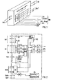
- FIG. 1 shows, in one embodiment of the invention, a slot-in cassette shown in perspective, which contains, as a subscriber set, all subscriber-specific devices with broadband and narrowband multiplexers, with switching functions and associated controls, and the electro-optical converters.
- the horizontal bus lines carry the broadband signals such as TV channels, video telephone lines, radio, clocks and power supply.
- the fiber optic connection LWL leading to the subscriber can be seen on the left front transverse side.
- the narrowband signals SB to be conveyed (telegraphy, telephony, etc.) and, under certain circumstances, a video telephone line Bif * can be connected to the rear transverse side, which is switched centrally.
- FIG. 2 contains the block diagram for the subscriber set according to FIG. 1 (dash-dotted line).
- the broadband bus inputs can be seen on the left with Bif, TV and radio, with three TV signals or two TV signals and Bif being selectable from the Bif and TV signals, which together with the radio signal to which the narrowband signals ( ISDN) are added in a broadband pre-multiplexer BB-VOR-MUX, combined in a broadband multiplexer BBMUX and transferred via a switch to an electro-optical converter which feeds the fiber optic cable to the subscriber.
- BB-VOR-MUX broadband pre-multiplexer
- BBMUX broadband multiplexer
- the signals arriving from the subscriber are converted into electrical signals by means of an optoelectronic converter and fed via a switch to a demultiplexer D-MUX, which outputs the narrowband signals ISDN and, if applicable, video telephone signals Bif.
- the phase adjustment of the signals required before the multiplexing is carried out by multiple sampling (punctured diamond).
- the complex identified by the dashed outline corresponds to the subscriber interface unit TAE, the functions of which according to the invention are combined on a highly integrated chip.
- the functions can also be implemented with standard integrated circuits and, if necessary, broadband coupling points.
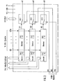
- the channel selector according to the invention contains three similar devices, each consisting of a ( ) Decoder ( ) Demultiplexers and switches US exist.
- the 16 broadband channels E1 to E16 are managed with binary, digital signals (e.g. ECL interface, approx. 70 megabits / sec each).
- a broadband channel is switched to one of the outputs D1 to D3.
- the switches US1 to US3 either the signals D1 to D3 or the signals B1 to B3 are switched through to the outputs A1 to A3 of the channel selector. 3 bits are provided for switch selection.
- the changes in the addresses take place very slowly, for example in the range of seconds, so that the address lines can be routed between the broadband channel lines as shielded or coupling lines.
- the channel selector is supplied with power via the VCC connections, and the channel selector can be switched off from the power supply via the PD connection.
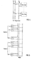
- Fig. 4 shows a broadband bus, the TV program rails at the beginning and at the end are almost completed with their wave resistance.
- the taps to the subscriber sets are high-resistance, the resistors sit on the tub wiring board, so that reflections caused by the plug connections have no effect.
- the amplifiers drawn at the bus input are, for example, ECL drivers, which are required once for each tank.
- FIG. 5 shows a circuit suitable for decentralized structures for decentralized video telephone exchange for 12 subscribers and 6 paths, external connections which can be connected to the BIF paths by means of line sets or conference circuit sets not being shown.
Landscapes
- Engineering & Computer Science (AREA)
- Computer Networks & Wireless Communication (AREA)
- Signal Processing (AREA)
- Multimedia (AREA)
- Two-Way Televisions, Distribution Of Moving Picture Or The Like (AREA)
- Use Of Switch Circuits For Exchanges And Methods Of Control Of Multiplex Exchanges (AREA)
- Small-Scale Networks (AREA)
Abstract
Description
- Die Erfindung betrifft ein breitbandintegriertes Glasfaserortsnetz zur Versorgung von Teilnehmern gemäß Oberbegriff des Anspruchs 1.
- Ein solches dienstintegriertes Nachrichtenübertragungs-und Vermittlungssystem ist durch die DE-OS 29 22 418 bekannt geworden, bei dem in der Zentrale ein Video- und ein Audio-Koppelfeld zur Versorgung des Teilnehmers mit zwei TV- und 10 UKW-Programmen, die durch den Teilnehmer mittels eines Steuersignals in der Rückrichtung aus der angebotenen Vielzahl von Fernseh- und Rundfunkprogrammen ausgewählt werden können.
- Ein solches Video- oder Audio-Koppelfeld erfordert eine umständliche und aufwendige Leitungsführung in der Zentrale, die umso größer ist, je mehr Programme dem einzelnen Teilnehmer gleichzeitig angeboten werden. Gegenwärtige Planungen gehen von drei Fernsehprogrammen aus 16 angebotenen und von einer Verteilung der Signale auf unterschiedliche Teilnehmeranzahlen bis zur Größe eines Fernmeldeortsnetzbereichs aus. Es ist einzusehen, daß zwischen Koppelfeld und Teilnehmermultiplexer zur Entkopplung bzw. Entstörung der Verbindungs- und Steuerleitungen ein hoher Aufwand, z. B. in Koaxialtechnik, erforderlich ist.
- Aufgabe der vorliegenden Erfindung war es deshalb, ein Netz der obigen Art anzugeben, bei dem auf der Vermittlungsseite weniger Leitungsführungsaufwand erforderlich ist.
- Die Lösung dieser Aufgabe erfolgt mit den in den Patentansprüchen angegebenen Mitteln.
- Durch die erfindungsgemäße Aufteilung eines zentralen Koppelfeldes in jeweils einem Teilnehmer zugeordnete dezentrale Koppeleinrichtungen und durch die Zuführung der zu verteilenden Breitbandsignale über Bus-Leitungen werden sehr viele Leitungen eingespart, beispielsweise wird nunmehr nur noch eine Anzahl von 16 Zuleitungen für TV benötigt gegenüber der Lösung des Standes der Technik mit dem Dreifachen der anzuschließenden Teilnehmeranzahl. In gleicher Weise wird der Aufwand für die Steuerung vermindert.
- In einer Weiterbildung der Erfindung sind alle teilnehmerindividuellen Einrichtungen zusammengefaßt, wobei optoelektronische Umsetzer, die BB- und SB-Multiplexer, die Vermittlungsfunktionen und die dazugehörigen Steuerungen in einheitlichen Einschubkassetten untergebracht werden können. Durch diese Zusammenfassung ist es möglich, die Teilnehmeranschalteeinheit in Hochintegrationstechnik, z.B. mittels Gatterreihen auf kundenspezifischen Schaltkreischips herzustellen.
- In einer weiteren Ausgestaltung der Erfindung ist es durch Kaskadierung von Selektorschaltern möglich, die Anzahl der angebotenen Fernsehprogramme oder anderer Breitbandienste beliebig zu erweitern.
- In einer weiteren Ausgestaltung der Erfindung enthält- jede Teilnehmeranschalteeinheit eine überwachungsschaltung, mit der es möglich ist, aufgrund eines von der Teilnehmerstelleneinrichtung abgegebenen Kennzeichens, das die Passivität des Teilnehmers kennzeichnet, die nicht benötigten Teile der Teilnehmeranschalteeinheit abzuschalten und damit Strom zu sparen.
- In einer anderen Ausgestaltung der Erfindung werden die Bus-Leitungen für die zu verteilenden Breitbandsignale nicht als Koaxialkabel ausgeführt, sondern als Mikrostrip-Leitungen im Zuge der Wannenverdrahtung, beispielsweise als Multilayer. Anstelle von Koaxsteckern können selbstverständlich billige Vielfachstecker verwendet werden.
- Im übrigen weist der erfindungsgemäße Aufbau den Vorteil der .einfachen Servitierbarkeit, einer guten Fehlerortungsmöglichkeit, minimaler Fehlerwirkungsbreite und einer leichten Erweiterbarkeit der Teilnehmeranzahl auf.
- Es folgt nun die Beschreibung der Erfindung anhand der Ausführungsbeispiele darstellenden Figuren.
- Die Fig. 1 zeigt in einer Ausgestaltung der Erfindung eine perspektivisch dargestellte Einschubkassette, die als Teilnehmersatz alle teilnehmerindividuellen Einrichtungen mit Breitband- und Schmalband-Multiplexern, mit Vermittlungsfunktionen und zugehöriger Steuerung sowie die elektro-optischen Umsetzer enthält. Die waagrecht verlaufenden Bus-Leitungen führen die Breitbandsignale wie TV-Kanäle, Bildfernsprechwege, Rundfunk sowie Takte und Stromversorgung. An der linken vorderen Querseite ist der Lichtwellenleiteranschluß LWL erkennbar, der zum Teilnehmer führt. An der hinteren Querseite sind die zu vermittelnden Schmalbandsignale SB (Telegrafie, Telefonie usw.) sowie unter Umständen eine Bildfernsprechleitung Bif* anschließbar, die zentral vermittelt ist.
- Die Fig. 2 enthält das Blockschaltbild zum Teilnehmersatz nach Fig. 1 (strichpunktiert). Linksseitig sind die Breitband-Bus-Eingänge erkennbar mit Bif, TV und Rundfunk, wobei aus den Bif- und TV-Signalen drei TV-Signale oder zwei TV-Signale und Bif auswählbar sind, die zusammen mit dem Rundfunksignal, zu dem die Schmalbandsignale (ISDN) in einem Breitbandvormultiplexer BB-VOR-MUX zugefügt werden, in einem Breitbandmultiplexer BBMUX zusammengefaßt und über einen Umschalter auf einen elektro-optischen Wandler gegeben werden, der die Glasfaserleitung LWL zum Teilnehmer hin speist. In der Rückrichtung werden die vom Teilnehmer ankommenden Signale mittels optoelektronischem Wandler in elektrische Signale umgesetzt und über einen Umschalter einem Demultiplexer D-MUX zugeführt, der die Schmalbandsignale ISDN und gegebenenfalls Bildfernsprechsignale Bif abgibt. Die vor der Multiplexzusammenfassung erforderliche Phasenanpassung der Signale erfolgt durch Mehrfachabtastung (punktisiertes Karo).
- Der durch die strichlierte Umrandung gekennzeichnete Komplex entspricht der Teilnehmeranschalteeinheit TAE, deren Funktionen erfindungsgemäß auf einem hochintegrierten Chip zusammengefaßt werden. Selbstverständlich_lassen sich die Funktionen auch mit standardintegrierten Schaltkreisen und gegebenenfalls Breitbandkoppelpunkten realisieren.
- Ferner ist erkennbar, wie aus einem Schmalbandrückkanal die Kennzeichen der Teilnehmerstelleneinrichtung erkannt (HKZ) und einer Steuerungs- und Überwachungsschaltung entsprechende Befehle zugeführt werden, mit deren Hilfe die vom Teilnehmer nicht benötigten Sghaltungsteile des Teilnehmersatzes abgeschaltet werden oder bei einen ein Fernsehprogramm auswählenden Teilnehmer das entsprechende Auswahladressenzeichen festgestellt und den entsprechenden Selektoren bzw. Decodern zugeführt wird.
- In Fig. 3 ist ein erfindungsgemäßer Selektor mittels Blockschaltbild dargestellt. Der erfindungsgemäße Kanalselektor enthält drei gleichartige Einrichtungen, die jeweils aus einem (


- Die Fig. 4 zeigt einen Breitband-Bus, wobei die TV-Programmschienen am Anfang und am Ende annähernd mit ihrem Wellenwiderstand abgeschlossen sind. Die Abgriffe zu den Teilnehmersätzen sind hochohmig, die Widerstände sitzen auf der Wannenverdrahtungsplatte, so daß von den Steckverbindungen verursachte Reflexionen keine Auswirkungen haben. Die am Buseingang gezeichneten Verstärker sind beispielsweise ECL-Treiber, die für jede Wanne einmal erforderlich sind.
- Die Fig. 5 stellt eine für dezentrale Strukturen geeignete Schaltung zur dezentralen Bildfernsprechvermittlung für 12 Teilnehmer und 6 Wege dar, wobei externe Verbindungen, die mittels Leitungssätzen oder Konferenzschaltungssätzen an die Bif-Wege anschließbar sind, nicht dargestellt sind.
Claims (10)


Applications Claiming Priority (2)
| Application Number | Priority Date | Filing Date | Title |
|---|---|---|---|
| DE3138473 | 1981-09-26 | ||
| DE19813138473 DE3138473A1 (de) | 1981-09-26 | 1981-09-26 | Dienstintegriertes nachrichtenuebertragungs- und vermittlungsnetz fuer bild, ton und daten |
Publications (3)
| Publication Number | Publication Date |
|---|---|
| EP0076362A2 true EP0076362A2 (de) | 1983-04-13 |
| EP0076362A3 EP0076362A3 (en) | 1983-05-11 |
| EP0076362B1 EP0076362B1 (de) | 1986-03-05 |
Family
ID=6142765
Family Applications (1)
| Application Number | Title | Priority Date | Filing Date |
|---|---|---|---|
| EP82105543A Expired EP0076362B1 (de) | 1981-09-26 | 1982-06-24 | Dienstintegriertes Nachrichtenübertragungs- und Vermittlungsnetz für Bild, Ton und Daten |
Country Status (2)
| Country | Link |
|---|---|
| EP (1) | EP0076362B1 (de) |
| DE (2) | DE3138473A1 (de) |
Cited By (6)
| Publication number | Priority date | Publication date | Assignee | Title |
|---|---|---|---|---|
| EP0144075A3 (de) * | 1983-12-01 | 1987-05-20 | ANT Nachrichtentechnik GmbH | Dienstintegriertes, digitales Nachrichtenübertragungssystem |
| EP0144076A3 (en) * | 1983-12-01 | 1987-05-27 | Ant Nachrichtentechnik Gmbh | Integrated services digital transmission network |
| EP0144077A3 (de) * | 1983-12-01 | 1987-05-27 | ANT Nachrichtentechnik GmbH | Dienstintegriertes, digitales Nachrichtenübertragungssystem |
| EP0174099A3 (en) * | 1984-08-06 | 1990-03-07 | Texas Instruments Incorporated | Fiber optic terminal interface |
| EP0288675A3 (de) * | 1987-04-25 | 1991-03-27 | KABEL RHEYDT Aktiengesellschaft | Digitales Übertragungssystem |
| US5903372A (en) * | 1997-02-10 | 1999-05-11 | Alcatel Network Systems, Inc. | Means for remote addition of video services to subscribers |
Families Citing this family (2)
| Publication number | Priority date | Publication date | Assignee | Title |
|---|---|---|---|---|
| DE4333367A1 (de) * | 1993-09-30 | 1995-04-06 | Ant Nachrichtentech | Sender und Empfänger für ein optisches Nachrichtenübertragungssystem |
| DE4409458A1 (de) * | 1994-03-18 | 1995-09-21 | Sel Alcatel Ag | Telekommunikationsendgerät insbesondere für elektronische Massenpost und Nachrichtenverteilnetz |
Family Cites Families (9)
| Publication number | Priority date | Publication date | Assignee | Title |
|---|---|---|---|---|
| CH564889A5 (de) * | 1973-11-28 | 1975-07-31 | Patelhold Patentverwertung | |
| DE2421002C3 (de) * | 1974-04-30 | 1980-07-03 | Siemens Ag, 1000 Berlin Und 8000 Muenchen | Nachrichtenvermittlungssystem |
| DE2603644C3 (de) * | 1976-01-30 | 1980-02-28 | Siemens Ag, 1000 Berlin Und 8000 Muenchen | Gemeinschaftsantennenanlage |
| DE2700393C2 (de) * | 1977-01-07 | 1982-12-16 | Dieter Prof. Dr.-Ing. 8520 Erlangen Seitzer | Tonsignalübertragung in einem Fernsprechverteilnetz |
| DE2905757A1 (de) * | 1979-02-15 | 1980-09-04 | Licentia Gmbh | Vorrichtung zur uebertragung von informationen zwischen stationen |
| DE2944784C2 (de) * | 1979-11-06 | 1982-04-29 | Siemens Ag, 1000 Berlin Und 8000 Muenchen | Breitband-Vermittlungssystem |
| DE2951512A1 (de) * | 1979-12-20 | 1981-07-02 | Siemens AG, 1000 Berlin und 8000 München | Breitband-vermittlungssystem |
| DE3022725A1 (de) * | 1980-06-18 | 1981-12-24 | Licentia Patent-Verwaltungs-Gmbh, 6000 Frankfurt | Dienstintegriertes nachrichtenuebertragungs- und vermittlungssystem |
| DE3045875A1 (de) * | 1980-12-05 | 1982-09-09 | Licentia Patent-Verwaltungs-Gmbh, 6000 Frankfurt | Dienstintegriertes, digitales uebertragungssystem |
-
1981
- 1981-09-26 DE DE19813138473 patent/DE3138473A1/de not_active Withdrawn
-
1982
- 1982-06-24 EP EP82105543A patent/EP0076362B1/de not_active Expired
- 1982-06-24 DE DE8282105543T patent/DE3269608D1/de not_active Expired
Cited By (6)
| Publication number | Priority date | Publication date | Assignee | Title |
|---|---|---|---|---|
| EP0144075A3 (de) * | 1983-12-01 | 1987-05-20 | ANT Nachrichtentechnik GmbH | Dienstintegriertes, digitales Nachrichtenübertragungssystem |
| EP0144076A3 (en) * | 1983-12-01 | 1987-05-27 | Ant Nachrichtentechnik Gmbh | Integrated services digital transmission network |
| EP0144077A3 (de) * | 1983-12-01 | 1987-05-27 | ANT Nachrichtentechnik GmbH | Dienstintegriertes, digitales Nachrichtenübertragungssystem |
| EP0174099A3 (en) * | 1984-08-06 | 1990-03-07 | Texas Instruments Incorporated | Fiber optic terminal interface |
| EP0288675A3 (de) * | 1987-04-25 | 1991-03-27 | KABEL RHEYDT Aktiengesellschaft | Digitales Übertragungssystem |
| US5903372A (en) * | 1997-02-10 | 1999-05-11 | Alcatel Network Systems, Inc. | Means for remote addition of video services to subscribers |
Also Published As
| Publication number | Publication date |
|---|---|
| EP0076362A3 (en) | 1983-05-11 |
| DE3269608D1 (en) | 1986-04-10 |
| DE3138473A1 (de) | 1983-05-26 |
| EP0076362B1 (de) | 1986-03-05 |
Similar Documents
| Publication | Publication Date | Title |
|---|---|---|
| DE69010011T2 (de) | Kommunikationssystem. | |
| DE3614361C2 (de) | ||
| EP0151454B1 (de) | Breitbandiges integriertes Teilnehmeranschlusssystem | |
| DE2922418C2 (de) | Dienstintegriertes Nachrichtenübertragungs- und Vermittlungssystem für Ton, Bild und Daten | |
| DE69226075T2 (de) | Kommunikationskoppelfeld | |
| EP0028416A1 (de) | Breitband-Vermittlungssystem | |
| EP0076362B1 (de) | Dienstintegriertes Nachrichtenübertragungs- und Vermittlungsnetz für Bild, Ton und Daten | |
| DE3418618C2 (de) | ||
| EP0196527A2 (de) | Verteileinrichtung für digitalisierte Fernsehsignale | |
| EP0060318A1 (de) | Breitband-Vermittlungssystem | |
| DE3789137T2 (de) | Verfahren zur Erweiterung der Uebertragungskapazität in einem Netzwerkübertragungssystem für optische Teilnehmer. | |
| WO2006122698A1 (de) | Aktive verteilereinrichtung im teilnehmeranschlussbereich | |
| EP0071232B1 (de) | Breitbandkommunikationssystem | |
| DE3129467A1 (de) | Fernmeldesystem mit einer durchschalteeinrichtung fuer breitbandige signale | |
| DE3343473A1 (de) | Dienstintegriertes, digitales nachrichtenuebertragungssystem | |
| EP0730800B1 (de) | Verfahren und schaltungsanordnung zur verteilung von sendeprogramminformationen, vorzugsweise in breitband-fernmeldewählnetzen | |
| DE3783149T2 (de) | Tst-typ-vermittlungssystem fuer breitbandvermittlung. | |
| DE19756438A1 (de) | Anordnung zur leitungsgebundenen digitalen Nachrichtenübertragung | |
| EP0144075A2 (de) | Dienstintegriertes, digitales Nachrichtenübertragungssystem | |
| DE3335676C2 (de) | ||
| DE19530783C2 (de) | Verfahren zur digitalen Übertragung von nachrichtentechnischen Diensten | |
| DE3645306C2 (de) | Kommunikationssystem für Videoinformationen | |
| DE19727670C1 (de) | Einrichtung zur Verteilung von Breitbandsignalen | |
| DE3416036A1 (de) | Vermittlungs- und verteileinrichtung | |
| DE3645247C2 (de) | Knotenvollbindspeicher zur Speicherung eines Fernsehstandbildes in einem Kabelfernsehsystem |
Legal Events
| Date | Code | Title | Description |
|---|---|---|---|
| PUAI | Public reference made under article 153(3) epc to a published international application that has entered the european phase |
Free format text: ORIGINAL CODE: 0009012 |
|
| PUAL | Search report despatched |
Free format text: ORIGINAL CODE: 0009013 |
|
| AK | Designated contracting states |
Designated state(s): BE DE FR GB IT LU NL |
|
| RAP1 | Party data changed (applicant data changed or rights of an application transferred) |
Owner name: AEG - TELEFUNKEN NACHRICHTENTECHNIK GMBH |
|
| AK | Designated contracting states |
Designated state(s): BE DE FR GB IT LU NL |
|
| RAP1 | Party data changed (applicant data changed or rights of an application transferred) |
Owner name: ANT NACHRICHTENTECHNIK GMBH |
|
| 17P | Request for examination filed |
Effective date: 19831110 |
|
| ITF | It: translation for a ep patent filed | ||
| GRAA | (expected) grant |
Free format text: ORIGINAL CODE: 0009210 |
|
| AK | Designated contracting states |
Kind code of ref document: B1 Designated state(s): BE DE FR GB IT LU NL |
|
| ET | Fr: translation filed | ||
| REF | Corresponds to: |
Ref document number: 3269608 Country of ref document: DE Date of ref document: 19860410 |
|
| PG25 | Lapsed in a contracting state [announced via postgrant information from national office to epo] |
Ref country code: LU Free format text: LAPSE BECAUSE OF NON-PAYMENT OF DUE FEES Effective date: 19860630 |
|
| PLBI | Opposition filed |
Free format text: ORIGINAL CODE: 0009260 |
|
| 26 | Opposition filed |
Opponent name: STANDARD ELEKTRIK LORENZ AG Effective date: 19861127 |
|
| NLR1 | Nl: opposition has been filed with the epo |
Opponent name: STANDARD ELEKTRIK LORENZ AG |
|
| PGFP | Annual fee paid to national office [announced via postgrant information from national office to epo] |
Ref country code: NL Payment date: 19870630 Year of fee payment: 6 |
|
| RDAG | Patent revoked |
Free format text: ORIGINAL CODE: 0009271 |
|
| STAA | Information on the status of an ep patent application or granted ep patent |
Free format text: STATUS: PATENT REVOKED |
|
| PGFP | Annual fee paid to national office [announced via postgrant information from national office to epo] |
Ref country code: FR Payment date: 19890615 Year of fee payment: 8 |
|
| PGFP | Annual fee paid to national office [announced via postgrant information from national office to epo] |
Ref country code: LU Payment date: 19890627 Year of fee payment: 8 |
|
| 27W | Patent revoked |
Effective date: 19890211 |
|
| GBPR | Gb: patent revoked under art. 102 of the ep convention designating the uk as contracting state | ||
| ITTA | It: last paid annual fee | ||
| PGFP | Annual fee paid to national office [announced via postgrant information from national office to epo] |
Ref country code: GB Payment date: 19890630 Year of fee payment: 8 |
|
| PGFP | Annual fee paid to national office [announced via postgrant information from national office to epo] |
Ref country code: BE Payment date: 19890803 Year of fee payment: 8 |
|
| NLR2 | Nl: decision of opposition | ||
| BERE | Be: lapsed |
Owner name: ANT NACHRICHTENTECHNIK G.M.B.H. Effective date: 19900630 |