EP0076507A2 - Récipient pour un échantillon pâteux - Google Patents
Récipient pour un échantillon pâteux Download PDFInfo
- Publication number
- EP0076507A2 EP0076507A2 EP82109157A EP82109157A EP0076507A2 EP 0076507 A2 EP0076507 A2 EP 0076507A2 EP 82109157 A EP82109157 A EP 82109157A EP 82109157 A EP82109157 A EP 82109157A EP 0076507 A2 EP0076507 A2 EP 0076507A2
- Authority
- EP
- European Patent Office
- Prior art keywords
- vessel
- sample
- projection
- recess
- vessel according
- Prior art date
- Legal status (The legal status is an assumption and is not a legal conclusion. Google has not performed a legal analysis and makes no representation as to the accuracy of the status listed.)
- Granted
Links
Images



Classifications
-
- A—HUMAN NECESSITIES
- A61—MEDICAL OR VETERINARY SCIENCE; HYGIENE
- A61B—DIAGNOSIS; SURGERY; IDENTIFICATION
- A61B10/00—Instruments for taking body samples for diagnostic purposes; Other methods or instruments for diagnosis, e.g. for vaccination diagnosis, sex determination or ovulation-period determination; Throat striking implements
- A61B10/0038—Devices for taking faeces samples; Faecal examination devices
-
- B—PERFORMING OPERATIONS; TRANSPORTING
- B01—PHYSICAL OR CHEMICAL PROCESSES OR APPARATUS IN GENERAL
- B01F—MIXING, e.g. DISSOLVING, EMULSIFYING OR DISPERSING
- B01F33/00—Other mixers; Mixing plants; Combinations of mixers
- B01F33/25—Mixers with loose mixing elements, e.g. loose balls in a receptacle
- B01F33/254—Mixers with loose mixing elements, e.g. loose balls in a receptacle using springs as loose mixing element
Definitions
- the invention relates to a vessel for handling pasty sample material with an optionally tubular vessel part and a lid part which is plugged onto the vessel part and which optionally closes off as a homogenization chamber and ends with a possibly cylindrical projection protruding substantially vertically on the inside of the lid part facing the vessel interior. at its free end, a sample recess open to the interior of the vessel for receiving the sample material is formed, the volume of which corresponds to the desired sample volume.
- the vessel part is formed in the region of its opening for the lid part with a stripping collar adapted to the cross section of the projection for sample material attached to the circumference of the projection, and in that on the side of the stripping collar remote from the interior of the vessel in the lid part and / or an annular space for receiving stripped sample material is formed in the vessel part.
- the sample material therefore only has to be poured into the sample recess and then smoothed out; the cover part can then be placed immediately on the vessel part, the stripping collar inevitably ensuring that excess sample material is stripped off at the periphery of the projection and deposited in the annular space outside the interior of the vessel. The possibly extremely unpleasant manual cleaning of the circumference of the projection is completely eliminated.
- a device for dosing and examining stool samples in which the End face of a projection of the cover part 4 is flat, that is, has no sample recess for receiving the sample material, the volume of which corresponds to the desired sample volume.
- the sample is dosed by filling sample material into a cylinder ring that defines the interior of the vessel 8 and is open at the top, whereupon by closing the cover part 4, the protrusion penetrates into the cylinder ring, with open, axially extending slots 13 initially allow the sample ring to swell out excess sample material laterally.
- the protrusion with the cylinder ring closes somewhat tightly in the manner of a piston, as a result of which the metered sample volume is determined.
- the lid part 4 is moved further towards the vessel part 1, with the result that the sample material is pressed onto a filter paper located below the cylinder ring, whereby liquid portions of the sample material can be obtained for the subsequent examination.
- the sample is dosed before the lid part is placed on the vessel part, namely by filling the sample into the sample recess within the lid part and then smoothing it.
- the cover part and the vessel part be formed with a peripheral seal which seals off the annular space, preferably in the form of a protruding part on the inside of the cover part Circumferential collar, which rests with an inner circumferential surface in a sealing manner on an outer circumferential surface of a circumferential shoulder of the vessel part.
- the projection protrude beyond the circumferential collar, preferably 1 to 5 mm, preferably about 2 mm.
- the vessel part be provided with a further opening which is connected to the interior of the vessel and which is closed by an additional lid part which can be removed again. This makes it possible to add additives such as e.g. Fill in solvents or homogenizing elements without having to loosen the cover part, which may carry unsightly sample material. In this way, the annoyance of the laboratory personnel during the preparation of the test measurements of the sample material is significantly reduced.
- a simple and inexpensive to manufacture embodiment of the vessel is characterized in that the tubular vessel part is closed at one of its tube ends with the cover part and at the other tube end with the additional cover part. It is also advantageous that the tubular vessel can be sent in the usual way by post.
- the cover part and / or Z are usatzdeckelteil each connected preferably in one piece via a connection link with the vessel part.
- the lid part and the additional lid part are therefore captively connected to the vessel part. It is also particularly advantageous that it is now possible to produce a single part, in particular an injection molded plastic part, which greatly reduces the production costs.
- the cover part and / or the additional cover part be connected with a grip tab, preferably in one piece.
- the vessel part can also be used, for example, to centrifuge the sample material in solution in the interior of the vessel if the vessel is designed such that the vessel part and the lid and / or the additional lid part have an outer diameter of approximately 17 mm , and that the connecting and grip tabs can be easily separated, preferably via predetermined breaking points.
- the commercially available centrifuges have receiving bores of approximately 18 mm inside diameter and are therefore suitable for receiving the vessels designed according to the invention. Connecting or grip tabs protruding from the outside diameter of the vessel of approx. 17 mm can be easily separated due to the predetermined breaking points.
- the sample recess diameter is generally much smaller than the corresponding dimension of the interior of the vessel.
- the homogenization element (s) glass or steel balls, rods or the like
- the inside of the part of the vessel delimiting the interior of the vessel preferably tapers towards the sample recess in the lid part.
- the vessel part bears with a preferably undercut inner circumferential collar on the end face of the projection in the region of the edge of the P robenausnaturalung. The surplus ge sample material is thus held between the inner circumferential collar and the end face of the projection.
- a preferred embodiment of the invention is characterized by a spirally designed homogenization rod which can be inserted into the interior of the vessel and whose spiral diameter is adapted to the inside diameter of the vessel.
- the homogenization rod provides for an intensive comminution and mixing of the sample material with the solution, because due to its spiral design it rotates around its longitudinal axis during its reciprocation within the interior of the vessel. It is preferably provided that the rod end of the homogenizing rod, which is close to the sample recess, extends essentially in the direction of the spiral axis, preferably at a distance from the spiral axis, which ensures complete removal of the sample material even from any corner areas at the bottom of the sample recess.
- the homogenization rod therefore ensures complete dissolution of the sample material, whereby larger sample particles are also broken up finely.
- the known glass spheres used for homogenization on the other hand, there is the risk that at least some of the sample material is not detached from the sample recess but, on the contrary, is pressed against the bottom of the sample recess by the balls; on the other hand is the shred The effect of the glass balls is often insufficient.
- a receptacle space for the protrusion which is adapted to the cross section of the protrusion, is preferably provided in the vessel part, at the protrusion insertion end of which the stripping collar is arranged and at its opposite end, which merges into the vessel interior, possibly the undercut inner circumferential collar.
- the vessel wall preferably made of plastic, surrounding the receiving space is elastically deformed, which results in the desired, firm cohesion between the projection and the vessel part.
- the receiving space is designed to taper slightly into the interior of the vessel, in which case the projection has a cylindrical cross section.
- the conical design of the projection or receiving space also makes it easier to thread the projection into the housing opening. The taper is set so low that the stripping effect remains essentially unchanged.
- the circumferential collar can be fixed on the circumferential shoulder of the vessel part by means of a snap connection, preferably in the form of at least one circumferential elevation provided on one of the two parts, which engages in a circumferential recess provided on the other part.
- a snap connection preferably in the form of at least one circumferential elevation provided on one of the two parts, which engages in a circumferential recess provided on the other part.
- the invention also relates to a use of the vessel according to the invention for enzyme determination, preferably chymotrypsin or trypsin determination in stool, in particular for dosing stool samples in quantities of less than 1 g stool, preferably between 20 and 200 mg stool.
- the vessel according to the invention is particularly well suited for this because, on the one hand, the handling of the vessel takes place with the least possible strain on the patient and laboratory personnel and, on the other hand, because a well reproducible dosage of comparatively small stool samples is possible; the intended photometric activity determination is no longer possible for larger sample quantities due to the intrinsic color of the sample solution. Since only large amounts of sample can be dosed with sufficient accuracy in the known vessels, it has so far not been possible to routinely carry out photometric activity determination on stool.
- the vessel according to the invention can also be used for the sample transport of the stool sample from the patient to the laboratory as well as for the sample homogenization in the interior of the vessel to be carried out in the laboratory, preferably by loosening the additional lid part, adding homogenizing agent and homogenizing elements, preferably the homogenizing rod, pressing on the additional lid part and then shaking the vessel in a vibrating vibrator.
- the inserted spiral homogenization rod ensures perfect homogenization of the relatively small amount of sample, especially if it is always deflected into the sample recess due to the tapering inner surface of the vessel part.
- vessel to the invention can also be used for Z ene trifug Schlifuge by removing the connecting tabs, and grip lugs and subsequent insertion of the vessel.
- all of the processing steps preceding the actual, for example photometric, measurement can be carried out on the vessel according to the invention.
- the vessel has to be opened only once, namely to take an aliquot of the homogenized and, if necessary, centrifuged sample liquid. Laboratory personnel have no direct contact with the sample at all stages of the process.
- the vial can be destroyed after taking an aliquot.
- the use of the vessel according to the invention is not limited to the processing of stool samples, although it is particularly suitable for this.
- the vessel is generally suitable for dosing and homogenizing (possibly also centrifuging) paste-like sample materials (e.g. pastes and ointments from the pharmaceutical and food industries) to prepare ingredient analyzes.
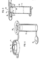
- the first embodiment of the vessel shown in FIGS. 1 and 2 is designated by 10. It consists of a vessel part 12, a cover part 14 (upper cover in FIGS. 1 and 2) and an additional cover part 16 (lower cover).
- the vessel part 12 has the shape of a hollow cylinder (tubular shape); its interior is referred to as the vessel interior 18.
- FIGS. 1 and 2 The structure of the cover part 14 is shown in FIGS. 1 and 2. From a flat cover plate 22 which is perpendicular to the axis 20, a cylindrical projection 24 which is central to the axis 20 and a hollow cylindrical edge 26 which is symmetrical to the axis 20 and which is flush with the axis 20 in FIGS. 1 and 2 project downwards (ie on the inside of the cover part) Outer periphery of the cover plate 22 merges. Projection 24 and edge 26 define an annular groove 28 which is open downward in FIG. 1 between them in the radial direction. The small diameter of the annular groove 28, which corresponds to the diameter of the projection 24, is denoted by a in FIG. 1; accordingly the large diameter of the ring groove with b.
- the diameter b is smaller than the outer diameter k of the cylindrical vessel part 12.
- a cylindrical recess is formed in the edge 26, the diameter of which corresponds to the diameter k speaks.
- the edge 26 lies with a circumferential collar 29 with an enlarged inner diameter in a sealing manner against the outer circumference of the vessel part 12.
- a radial circular ring surface 30 also lies sealingly against the upper end face 32 of the vessel part 12 at the upper end of the recess mentioned in FIG. 1.
- a radially inwardly projecting inner circumferential collar 40 is formed on the end of the cylindrical receiving space 38 with the inner diameter corresponding to the diameter c of the projection 36, on the radial annular surface of which, in FIG. 1, faces upward in FIG. 1, the projection 24 with its radial end face 43 when the cover part is fully inserted 14 strikes.
- the diameter e of the sample recess 42 is, for example, 5.6 mm; the depth f of the recess is for example 2 or 4 mm. This corresponds in the case of S tuhlprobe a sample weight of about 50 mg or 100 mg.
- the volume of the interior of the vessel 18 is a multiple of the volume of the sample recess 42, for example 150 times.
- the inner part 44 of the vessel delimiting the interior 18 of the vessel is cylindrical in a lower section 46 in FIG. 1 and conical in the section 48 which adjoins the top.
- the diameter d of the cylindrical section 46 with 13 mm is 2 to 3 times the diameter e of the sample recess 42.
- the conical section 48 adjusts the width of the vessel interior 18 to that of the sample recess 42; the diameter of the section 48 is therefore at the lower end of the cone d and at the upper end of the cone e.
- the cone angle a is approx. 40 °.
- the conical section 48 ends at its upper end in FIG. 1 in the mentioned inner circumferential collar 40.
- the additional lid part 16 which consists of a flat circular plate 50 with a diameter adapted to the diameter d of the interior 18 of the vessel, a shaft seal of the additional lid part lying against the cylindrical inner wall of the vessel also being suitable. With a radially outwardly projecting edge 52, the additional cover part 16 lies sealingly on the lower end face of the vessel part 12.
- Both the cover part 14 and the additional cover part 16 can each be integrally connected to the vessel part 12 by means of a connecting strap 54 or 56.
- the cover part 14 is also, opposite the connecting tab 54, provided with a grip tab 58 which protrudes radially and can be provided with a corrugation 60.
- the connecting tabs 54 and 56 ensure that the lid part 14 and additional lid part 16 are captively attached to the vessel part 12.
- the grip tab 58 makes the hand easier habitation of the lid part 14 when dosing the sample.
- a corresponding grip tab 59 on the additional cover part 16 facilitates its release in the laboratory.
- the vessel consisting of vessel part 12, lid part 14 and additional lid part 16, including the tabs 54, 56, 58 and 59, can be designed as a one-piece molded part, in particular a plastic injection-molded part.
- a homogenization rod 62 shown schematically in FIG. 1, can be inserted into the interior 18 of the vessel.
- This consists of a spirally bent wire or plastic element, the upper rod end 64 of which is bent in the direction of the spiral axis 63 in FIG. 1.
- the axial length g of the homogenizing rod 62 is somewhat smaller (e.g. 10 mm smaller) than the total axial length of the sections 46 and 48 of the interior 18 of the vessel.
- the spiral diameter h is approximately 10 mm.
- the above vessel 10 is suitable for sample dosing, sample shipping, sample homogenization and sample centrifugation, as will be shown below using the example of a stool sample which is to be subjected to a chymotrypsin examination.
- the patient fills a stool sample into the sample recess 42 of the opened lid part 14 with a cardboard spatula and then with a flat spatula along the radial annular surface 43 surrounding the sample recess 42 (see FIG. 2), which cleanly closes the sample surface with the edge of the sample recess 42 results in a well-defined sample volume.
- the excess sample amounts possibly deposited during the smoothing of the spatula on the outer circumference of the cylindrical projection 24 in the region of the free end of the projection 24 do not have to be removed manually, but can remain there since they automatically shut off when the cover part 14 is subsequently closed the area of the free end of the projection 24 are conveyed into the annular space 34 and therefore do not reach the area of the vessel interior 18.
- the cylindrical projection 24 first reaches the receiving space 38, the diameter of which corresponds to that of the projection 24.
- the annular edge 39 common to the end face 32 and the annular space 38 and forming a wiping collar therefore wipes off the excess sample material which has accumulated on the circumference of the projection 24 and accumulates in the annular space 34.
- both the well-dosed sample material 66 located in the sample recess 42 and the excess sample material 68 in the annular space 34 are indicated with points.
- the annular space 34 is hermetically sealed to the outside via the peripheral collar 29, so that it there is neither an odor nuisance to the outside, nor even an outflow of sample material.
- the additional lid part 16 is of course closed.
- the sealed container 10 which is provided with a sample of, for example, 50 mg in the manner specified, can be used directly for dispatch, if appropriate used in a transport container.
- the additional lid part 16 is opened, the homogenizing rod 62 and e.g. 5 ml of homogenization solution added (vessel 10 rotated about a horizontal axis by 180 ° with respect to FIGS. 1 and 2), then the additional lid part 16 closed and then the whole vessel 10 with the lid part 14 down in a vibrating shaker.
- the vessel part 12 is shaken back and forth in the direction of its axis 20, which due to the inertia of the homogenizing rod 62 results in a relative movement of the rod 62 relative to the vessel 10 essentially in the direction of the axis 20.
- the rod 62 Due to its spiral structure, the rod 62 performs rotational movements in one and / or other direction, which has the consequence that the position and orientation of the rod 62 change constantly and thus also the position of the upper rod end 64, which can lie outside the spiral axis and is parallel to it.
- the conical section 48 deflects the rod 64 in such a way that the rod end 64 always pushes into the sample recess 42.
- the dimensions of the rod 64 ie rod length g and spiral diameter h) are adapted to the dimensions of the vessel interior 18 in such a way that there is sufficient play for the rod 62, so that the rod end 64 reaches practically all locations of the sample recess during shaking without that the rod 62 falls over.
- the sample material is therefore completely knocked out of the sample recess 42 by the rod 62 and comminuted by the rod windings.
- Adequate homogenization is achieved after about half a minute of shaking.
- the additional cover part 16 can then be opened for manual measurements and an aliquot (100 ⁇ l) of the suspension can be removed with the pipette for a laboratory test.
- the contents of the vessel can also be centrifuged immediately after homogenization, e.g. for automatic analysis.
- the tabs 54, 56, 58 and 59 are removed, but at least the tabs 54 and 58 in order to be able to insert the vessel 10 into a centrifuge opening.
- the maximum diameter i of the vessel 10 without tabs 54, 56 and 58 is adapted to the diameter of the centrifuge opening by approximately 17 mm.
- predetermined breaking points 70 are provided in FIG. 1.
- a second embodiment of the vessel, designated 110 is shown. Elements of the vessel 110 which correspond to those of the vessel 10 are provided with the same reference numbers, each increased by the number 100.
- the vessel 110 differs from the vessel 10 essentially only in that the outer diameter k of the vessel part 112 has been reduced in order to save material is with a corresponding increase in the axial length of the G efäßteils 112, to ensure unchanged volume of the vessel interior 118th
- the cover part 114 likewise has an edge 126 for sealing the annular space 134 to the outside and the projection 124 with a sample recess 142.
- the projection 124 projects in the axial direction (downward in FIG. 3) relative to the edge 126, so that when the lid part 114 is placed on the vessel part 112, the projection 124 first comes into contact with the vessel part 112.
- the additional cover part 116 seals the vessel interior 118 downwards.
- the use of the more inexpensive to produce vessel 110 is recommended when centrifugation can be omitted.
- the radially inwardly projecting inner circumferential collar 140 which forms the upper end of the conical section 148, is undercut on its upper side.
- the inner circumferential collar 140 rests with its inner edge 141 on the projection 124 in the manner of a lip seal, specifically in the region of the inner edge of the annular surface 143 (see FIG. 4).
- Excess sample residues which stick to the circular ring surface 143 when the cardboard spatula is not handled properly are therefore reliably held in the annular space 143 formed by the undercut and the circular ring surface 143 and sealed towards the inside when the cover part 114 is pressed on.
- a third embodiment of the vessel, designated 210 is shown, which is further simplified compared to the vessels 10 and 110.
- Elements of the vessel 210, which correspond to elements of the vessel 10 according to FIGS. 1 and 2, are with the the same reference numbers, each increased by the number 200.
- the container 210 can be opened briefly for sampling and an aliquot removed.
- the closed vessel in particular the lid part 214, can be pierced with a cannula and an aliquot removed.
- variants b) and c) there is no need to open the vessel 210 in the laboratory when taking a sample by means of a cannula.
- FIG. 7 shows a further embodiment of the vessel, designated 310, elements of this vessel, which correspond to those of the vessel 10 according to FIGS. 1 and 2, being provided with the same reference numbers, each increased by the number 300.
- the vessel 310 differs from the vessel 10, on the one hand, in that the projection 342 does not taper in a cylindrical manner but rather slightly conically in the direction of the sample recess 342 (cone angle / 3 approx. 5 °).
- the receptacle 338 is still cylindrical, the cylinder diameter being fixed in such a way that at the beginning of the insertion movement of the projection 342 into the receiving space 338 there is little play between the ring edge 339 at the upper end of the receiving space 338 and the lower end of the projection in FIG. 7 324 exists.
- the diameter of the receiving space 339 is smaller than the diameter of the undeformed conical projection 324 at the level of the ring edge 339 when the projection 324 is intended to be fully inserted into the receptacle 339. Because of this difference in diameter, a mutual Ver occurs when the projection 324 is fully inserted Formation of housing part 312 and cover part 314 or projection 324 in the region of the ring edge 339. The correspondingly increased frictional engagement with self-locking between the two parts prevents the two parts from being inadvertently detached from one another. Furthermore, an absolutely tight seal is obtained between the housing interior 318 and the annular space 334 between the vessel part 312 and the lid part 314.
- the vessel 310 differs from the vessel 10 according to FIGS. 1 and 2 further in that the circumferential edge 326 projecting axially in the same direction as the projection 324 is fixed to the outer circumference of the vessel part 314 via a snap connection.
- This snap connection consists of a beaded peripheral projection 380, e.g. on the outer circumference of the housing part 312, and a complementary circumferential recess 382 on the inner circumference of the edge 326. If necessary, a plurality of such circumferential projections or recesses can also be provided.
- This snap connection (with enlargement of the surfaces of the edge 326 and the vessel part 312 which are in contact with one another under prestress) forms a hermetic seal of the annular space 334 to the outside. In addition, this improves the hold of the closed lid part 314 on the vessel part 312 and at least greatly impedes inadvertent opening.
- the edge 326 is not stepped, which results in reduced use of material, as is the formation of the projection 324 with a recess 384 which is open towards the outside of the cover. If necessary, the edge 326 can of course correspond to the 1 to 6 can also be designed in a stepped manner, which facilitates the correct joining of the circumferential projection 380 and the circumferential recess 382. '
- the device according to the invention has proven to be particularly expedient for carrying out the method described by the applicant in German patent application P 31 39 719.0 under the name "Method for determining the activity of chymotrypsin or trypsin in stool".
- Method for determining the activity of chymotrypsin or trypsin in stool In these methods, relatively small, precisely dosed amounts of sample are suspended in the presence of a surface-active agent and then the rate of cleavage of a suitable substrate by the stool suspension is measured.
- the measurement of the rate of cleavage of the substrate can be carried out according to one of the methods known from the prior art, such as e.g. by titration of the released amino acid using an alkali (pH-stat method). It has been shown that when the process according to the invention is carried out in the presence of a surface-active agent, generally more than 90% of the enzyme activity is solubilized, the reaction rate of substrate cleavage is considerably increased and the apparent Km value of the substrate is reduced (activation factor approx 2 to 10), as a result of which the problems which have arisen up to now (in particular binding of the enzyme to the stool particles and surprisingly large km values for untreated stool samples compared to crystalline enzyme on certain substrates) can be overcome.
- a surface-active agent generally more than 90% of the enzyme activity is solubilized
- the reaction rate of substrate cleavage is considerably increased and the apparent Km value of the substrate is reduced (activation factor approx 2 to 10), as a result of which the problems which have arisen up to now
- any suitable surfactant can be used as the surface-active agent, such as anionic or ampholytic surfactants, and preferably nonionic surfactants and in particular cationic surfactants.
- Anionic surfactants are, for example, alkane sulfonates, olefin sulfonates, such as cumene sulphonate, ester sulfonates, alkylaryl sulfonates, alkyl benzene sulfonates, in particular from T yp lauryl sulfate sodium dodecylbenzenesulfonate and the alkyl naphthalene sulfonates, alkyl sulfates, such as, ether sulfates or fatty alcohol sulfates, salts of fatty acids and cholic acids;
- Ampholytic surfactants are those with anion-active and cation-active hydrophilic groups, such as, for example, glycerol derivatives with a betaine structure, sulfobetaines and lecithins;
- Non-ionic surfactants are, for example, polyethers, in particular alkylphenol polygly
- the choice of the most suitable surfactant also depends on the other reaction conditions, in particular on the type of enzyme and substrate, on the type and concentration of the salts, but also on the pH of the medium.
- Li cationic detergents which are never suitable have the greatest activation effect of quaternary ammonium compounds, preferably of the formula R1R2N (CH3) 2, in which R 1 preferably denotes an alkyl radical with 8 to 14 carbon atoms, and in particular lauryl and cetyl, and R 2 preferably denotes a lower alkyl radical with 1 to 5 carbon atoms or an aralkyl radical, or else a hydroxyalkyl radical, and in particular methyl or benzyl, and alkylpyridinium salts with preferably 12 to 18 carbon atoms in the alkyl radical, such as, for example, laurylpyridinium chloride, laurylpyridinium disulfate, and in particular the hexadecylpyridinium chloride.
- a particularly suitable surfactant for the process according to the invention is lauryl trimethyl ammonium chloride.
- the concentration of the surface-active agent in the homogenizing solution used to suspend the stool is generally from about 0.02 to about 10% by weight, preferably from 0.5 to 5% by weight.
- the concentration of the surface-active agent in the measurement solution (stool suspension and substrate solution) should advantageously be about 0.05 to 0.5, and preferably 0.1 to 0.3% by weight.
- the concentration of the stool sample in the suspension is e.g. when using the substrate Succ-Ala-Ala-Pro-Phe-pNA 0.2 to 0.5%.
- the homogenizing solution used to suspend the stool preferably also contains one or more water-soluble salts, such as, for example, alkali metal and / or alkaline earth metal chlorides or sulfate.
- water-soluble salts such as, for example, alkali metal and / or alkaline earth metal chlorides or sulfate.
- a NaCl content of 100 to 1000 mmol / 1 or a CaC1 2 content of 20 to 500 mmol / 1 or a combination of both salts in the concentration ranges mentioned has proven to be particularly expedient.
- organic salts for example acetates or citrates, are also suitable, as well as salts of other cations.
- the salts should expediently be present in a concentration which corresponds to an ionic strength of 20 to 1000 mVal / 1.
- any substrate known from the prior art for the determination of the activity of chymotrypsin or trypsin in stool can be used as a known substrate (see, for example, Grossman, Proc. Soc. Biol. Med. 110 (1962) , 41; Del Mar et al., Anal. Biochem. 99 (1979) 316; Nakajama et al., J. Biol. Chem. 254 (10), 1979, 4027-4032).
- the Ala-Ala-Phe-pNA and in particular the Succ-Ala-Ala-Pro-Phe-pNA and Me0 proved to be particularly suitable for the determination of chymotrypsin, especially with regard to water solubility, stability, Km value and rate constant -Succ-Arg-Pro-Tyr-pNA; they are particularly well suited for photometric determination.
- a well-suited substrate for the determination of trypsin activity is e.g. Chromozyme TRY (carbobenzoxy-valylglycyl-arginine-p-nitroanilide acetate).
- the substrate is in water or a mixture of water and an organic dissolved solvent.
- the organic solvent serves as a solubilizer for the substrate and is, for example, acetonitrile, dimethyl sulfoxide, acetone or methanol.
- the reagent solution preferably also contains the same salts as are used for the homogenizing solution; the concentration of these salts in the reagent solution is generally lower than the concentration in the homogenizing solution; the total salt concentration is preferably approximately 50 to 500 mmol / l, for example 250 mmol / 1 sodium chloride and 20 mmol / 1 calcium chloride.
- a certain amount of a suspension of the stool sample in the homogenizing solution or the centrifugation supernatant obtained by centrifugation until clarification is added to a certain amount of the reagent solution (e.g. 100 nl sample suspension to 2 ml of reagent solution) and the speed of the cleavage, for example, titrimetically or photometrically certainly.
- the amount of sample suspension depends on the achievement of well-measurable values, for example well-measurable increases in extinction / minute, above all on the expected enzyme activity.
- the pH of the homogenizing solution is not particularly critical; it is generally between 3 and 10, and in particular between 6 and 8.
- the buffer concentration is generally between 10 and 1000 mmol / l, in particular 50 to 200 mmol / l.
- the measurement can be carried out manually or with an automatic analyzer.
- an automatic analyzer For the photometric activity determination, and in particular for the automatic photometric measurement (determination of the absorbance), it is expedient to centrifuge the sample suspension before the measurement until it is clarified.
Landscapes
- Health & Medical Sciences (AREA)
- Life Sciences & Earth Sciences (AREA)
- General Health & Medical Sciences (AREA)
- Public Health (AREA)
- Biomedical Technology (AREA)
- Heart & Thoracic Surgery (AREA)
- Medical Informatics (AREA)
- Molecular Biology (AREA)
- Surgery (AREA)
- Animal Behavior & Ethology (AREA)
- Pathology (AREA)
- Engineering & Computer Science (AREA)
- Veterinary Medicine (AREA)
- Chemical & Material Sciences (AREA)
- Chemical Kinetics & Catalysis (AREA)
- Sampling And Sample Adjustment (AREA)
- Closures For Containers (AREA)
- Apparatus Associated With Microorganisms And Enzymes (AREA)
- Measuring Or Testing Involving Enzymes Or Micro-Organisms (AREA)
- Centrifugal Separators (AREA)
- Investigating Or Analysing Biological Materials (AREA)
Priority Applications (1)
| Application Number | Priority Date | Filing Date | Title |
|---|---|---|---|
| AT82109157T ATE26651T1 (de) | 1981-10-06 | 1982-10-04 | Gefaess zur handhabung von pastoesem probenmaterial. |
Applications Claiming Priority (2)
| Application Number | Priority Date | Filing Date | Title |
|---|---|---|---|
| DE3139702 | 1981-10-06 | ||
| DE19813139702 DE3139702A1 (de) | 1981-10-06 | 1981-10-06 | Gefaess zur handhabung von pastoesem probenmaterial |
Publications (3)
| Publication Number | Publication Date |
|---|---|
| EP0076507A2 true EP0076507A2 (fr) | 1983-04-13 |
| EP0076507A3 EP0076507A3 (en) | 1984-01-18 |
| EP0076507B1 EP0076507B1 (fr) | 1987-04-22 |
Family
ID=6143514
Family Applications (1)
| Application Number | Title | Priority Date | Filing Date |
|---|---|---|---|
| EP82109157A Expired EP0076507B1 (fr) | 1981-10-06 | 1982-10-04 | Récipient pour un échantillon pâteux |
Country Status (5)
| Country | Link |
|---|---|
| US (1) | US4514091A (fr) |
| EP (1) | EP0076507B1 (fr) |
| JP (1) | JPS5876082A (fr) |
| AT (1) | ATE26651T1 (fr) |
| DE (2) | DE3139702A1 (fr) |
Cited By (2)
| Publication number | Priority date | Publication date | Assignee | Title |
|---|---|---|---|---|
| EP0254793A1 (fr) * | 1986-07-31 | 1988-02-03 | SOCIETE SANDERS PROBEL BIOTECHNOLOGY, société anonyme | Dispositif pour le prélèvement dans une masse de matière, d'un volume déterminé de cette matière |
| WO2014096461A1 (fr) * | 2012-12-22 | 2014-06-26 | Frost Diagnostika Gmbh | Dispositif pour prélever et préparer un échantillon |
Families Citing this family (16)
| Publication number | Priority date | Publication date | Assignee | Title |
|---|---|---|---|---|
| DE29505652U1 (de) * | 1995-04-01 | 1996-04-25 | Boehringer Mannheim Gmbh, 68305 Mannheim | Gefäß zur kontaminationsreduzierten Behandlung von Flüssigkeiten |
| US5795061A (en) * | 1996-03-19 | 1998-08-18 | Brandeis University | Vortex mixing implement for sample vessels |
| AU2005316296B2 (en) * | 2004-12-16 | 2011-02-03 | Cepheid | Cap for vessel for performing multi-stage process |
| EP1839027B1 (fr) * | 2005-01-21 | 2016-10-19 | Medic Tools AG | Melangeur, homogeneisateur, extracteur, appareil de fractionnement ou appareil de mise en suspension a usage unique |
| US7624868B2 (en) * | 2005-12-01 | 2009-12-01 | Cook Vascular Incorporated | Pipette holder |
| JP6025514B2 (ja) * | 2012-11-13 | 2016-11-16 | 日本ケミコート化成株式会社 | 臨床検査用検体沈渣容器 |
| US9987634B2 (en) | 2014-12-03 | 2018-06-05 | Fiberlite Centrifuge, Llc | Centrifuge sample container and closure therefor |
| US10112199B2 (en) | 2014-12-03 | 2018-10-30 | Fiberlite Centrifuge, Llc | Centrifuge sample container and closure therefore |
| USD777941S1 (en) * | 2015-07-17 | 2017-01-31 | Fiberlite Centrifuge, Llc | Centrifuge bottle |
| US9999884B2 (en) | 2015-11-22 | 2018-06-19 | Invidx Corp. | Disposable cartridge |
| US10661270B2 (en) | 2015-11-22 | 2020-05-26 | Invidx Corp. | Disposable cartridge system for point-of-care testing |
| WO2018209418A1 (fr) * | 2017-05-16 | 2018-11-22 | Invidx Corp. | Cartouche jetable |
| US10272430B2 (en) | 2015-11-22 | 2019-04-30 | Invidx Corp. | Disposable cartridge with hinged cap |
| EP4385915A3 (fr) * | 2017-10-25 | 2024-09-11 | Hollister Incorporated | Capuchons pour emballages de cathéters |
| US11178158B2 (en) | 2018-01-29 | 2021-11-16 | Nagravision S.A. | Secure communication between in-vehicle electronic control units |
| CN109060494B (zh) * | 2018-08-25 | 2021-03-16 | 王明芳 | 用于肿瘤科免疫磁珠富集粪便脱落细胞的预处理装置 |
Family Cites Families (9)
| Publication number | Priority date | Publication date | Assignee | Title |
|---|---|---|---|---|
| US1060419A (en) * | 1913-02-12 | 1913-04-29 | Robert Benjamin | Mixing device. |
| US3185462A (en) * | 1960-04-22 | 1965-05-25 | Louis L Shore | Apparatus for mixing dental amalgam and separating excess mercury therefrom |
| US3101870A (en) * | 1960-10-12 | 1963-08-27 | Plastomatic Corp | Film sealed container with pouring spout |
| US4293405A (en) * | 1971-06-07 | 1981-10-06 | Greenwald Robert J | Fecal examination device (B) |
| FI52256C (fi) * | 1975-12-08 | 1977-07-11 | Osmo Antero Suovaniemi | Laite näytteiden ottamista varten näytteiden kuljettamiseksi ja analys oimiseksi. |
| IL52695A (en) * | 1977-08-10 | 1979-11-30 | Silmet Ltd | Mixing capsule |
| DE2810765C2 (de) * | 1978-03-13 | 1984-11-22 | Dr. Molter GmbH, 6901 Bammental | Laborzentrifuge |
| SE444639B (sv) * | 1978-08-02 | 1986-04-28 | Johnson & Johnson | Engangskapsel for dentalamalgam |
| DE2835358C2 (de) * | 1978-08-11 | 1980-08-14 | C.A. Greiner Und Soehne Gmbh & Co Kg, 7440 Nuertingen | Gefäß für biochemische und immunologische Untersuchungen |
-
1981
- 1981-10-06 DE DE19813139702 patent/DE3139702A1/de not_active Withdrawn
-
1982
- 1982-09-30 US US06/429,491 patent/US4514091A/en not_active Expired - Lifetime
- 1982-10-04 AT AT82109157T patent/ATE26651T1/de not_active IP Right Cessation
- 1982-10-04 JP JP57174431A patent/JPS5876082A/ja active Granted
- 1982-10-04 DE DE8282109157T patent/DE3276098D1/de not_active Expired
- 1982-10-04 EP EP82109157A patent/EP0076507B1/fr not_active Expired
Cited By (2)
| Publication number | Priority date | Publication date | Assignee | Title |
|---|---|---|---|---|
| EP0254793A1 (fr) * | 1986-07-31 | 1988-02-03 | SOCIETE SANDERS PROBEL BIOTECHNOLOGY, société anonyme | Dispositif pour le prélèvement dans une masse de matière, d'un volume déterminé de cette matière |
| WO2014096461A1 (fr) * | 2012-12-22 | 2014-06-26 | Frost Diagnostika Gmbh | Dispositif pour prélever et préparer un échantillon |
Also Published As
| Publication number | Publication date |
|---|---|
| DE3139702A1 (de) | 1983-04-21 |
| EP0076507B1 (fr) | 1987-04-22 |
| JPS6260067B2 (fr) | 1987-12-14 |
| US4514091A (en) | 1985-04-30 |
| JPS5876082A (ja) | 1983-05-09 |
| ATE26651T1 (de) | 1987-05-15 |
| EP0076507A3 (en) | 1984-01-18 |
| DE3276098D1 (en) | 1987-05-27 |
Similar Documents
| Publication | Publication Date | Title |
|---|---|---|
| EP0076507B1 (fr) | Récipient pour un échantillon pâteux | |
| DE60306232T2 (de) | Wattebauscheinrichtung und Verfahren | |
| DE69704223T2 (de) | Vorrichtung zur Durchführung von Reaktionen mit Erythrocyten | |
| DE69434867T2 (de) | Gerät zur Bestimmung eines Analyten in einer Probe | |
| EP1474235A1 (fr) | Dispositif de preparation d'echantillons et appareillage d'essai faisant appel a ce dernier | |
| EP0105194A1 (fr) | Chambres de centrifugation pour la préparation zytodiagnostique de cellules épithéliales et leurs utlisations | |
| EP2934338A1 (fr) | Dispositif pour prélever et préparer un échantillon | |
| EP0170980A2 (fr) | Dispositif de mélange et de vaporisation | |
| DE2625876B2 (de) | Vorrichtung zum Zubereiten von Flüssigkeitsproben zwecks Untersuchung und Analyse | |
| DE3308760A1 (de) | Vorrichtung zur mikroskopischen untersuchung von proben | |
| DE102014001386A1 (de) | Probenvorbereitungs- und Testsystem | |
| DE1598501B1 (de) | Verfahren und Vorrichtung zur Bemessung einer genauen Stoffprobenmenge | |
| DE3415580C2 (fr) | ||
| DE19641746C2 (de) | Pastenspender | |
| DE60129868T2 (de) | Verfahren zum Rühren einer Flüssigkeit | |
| DE2556636A1 (de) | Becher mit deckel | |
| DE69015358T2 (de) | Verfahren und vorrichtung zum dosieren eines volumens eines sedimentes oder einer flüssigkeit mit schlechten fliesseigenschaften. | |
| DE2535785A1 (de) | Spuelfluessigkeitsinjektor | |
| DE1930270A1 (de) | Verfahren und Vorrichtung zum Feststellen von Viskositaetsaenderungen,insbesondere fuer die Untersuchung der Blutgerinnung | |
| EP0991358B1 (fr) | Dispositif pour le prelevement et l'examen d'echantillons | |
| EP1714149A1 (fr) | Dispositif de passage destine a la mesure de la fonction plaquettaire de l'hemostase primaire, de l'agregation et/ou de la coagulation et/ou de la viscosite du sang | |
| DE20321610U1 (de) | Probenvorbereitungsvorrichtung und hierauf aufbauender Testgerätesatz | |
| DE69702915T2 (de) | Vorratsbehälter | |
| EP0327144B1 (fr) | Récipient pour recevoir un échantillon pâteux et procédé de traitement d'échantillons pâteux | |
| DE4039580A1 (de) | Reagenzbevorratungssystem und mehrfunktionsbehaelter fuer trockene reagenzkomponenten und anderes schuettgut |
Legal Events
| Date | Code | Title | Description |
|---|---|---|---|
| PUAI | Public reference made under article 153(3) epc to a published international application that has entered the european phase |
Free format text: ORIGINAL CODE: 0009012 |
|
| AK | Designated contracting states |
Designated state(s): AT BE CH DE FR GB IT LI LU NL SE |
|
| PUAL | Search report despatched |
Free format text: ORIGINAL CODE: 0009013 |
|
| AK | Designated contracting states |
Designated state(s): AT BE CH DE FR GB IT LI LU NL SE |
|
| 17P | Request for examination filed |
Effective date: 19840217 |
|
| 17Q | First examination report despatched |
Effective date: 19860410 |
|
| GRAA | (expected) grant |
Free format text: ORIGINAL CODE: 0009210 |
|
| AK | Designated contracting states |
Kind code of ref document: B1 Designated state(s): AT BE CH DE FR GB IT LI LU NL SE |
|
| REF | Corresponds to: |
Ref document number: 26651 Country of ref document: AT Date of ref document: 19870515 Kind code of ref document: T |
|
| ITF | It: translation for a ep patent filed | ||
| REF | Corresponds to: |
Ref document number: 3276098 Country of ref document: DE Date of ref document: 19870527 |
|
| ET | Fr: translation filed | ||
| PLBE | No opposition filed within time limit |
Free format text: ORIGINAL CODE: 0009261 |
|
| STAA | Information on the status of an ep patent application or granted ep patent |
Free format text: STATUS: NO OPPOSITION FILED WITHIN TIME LIMIT |
|
| 26N | No opposition filed | ||
| ITTA | It: last paid annual fee | ||
| EPTA | Lu: last paid annual fee | ||
| EAL | Se: european patent in force in sweden |
Ref document number: 82109157.6 |
|
| PGFP | Annual fee paid to national office [announced via postgrant information from national office to epo] |
Ref country code: DE Payment date: 20000925 Year of fee payment: 19 |
|
| PGFP | Annual fee paid to national office [announced via postgrant information from national office to epo] |
Ref country code: GB Payment date: 20001004 Year of fee payment: 19 |
|
| PGFP | Annual fee paid to national office [announced via postgrant information from national office to epo] |
Ref country code: LU Payment date: 20001006 Year of fee payment: 19 |
|
| PGFP | Annual fee paid to national office [announced via postgrant information from national office to epo] |
Ref country code: SE Payment date: 20001009 Year of fee payment: 19 |
|
| PGFP | Annual fee paid to national office [announced via postgrant information from national office to epo] |
Ref country code: FR Payment date: 20001010 Year of fee payment: 19 |
|
| PGFP | Annual fee paid to national office [announced via postgrant information from national office to epo] |
Ref country code: CH Payment date: 20001011 Year of fee payment: 19 Ref country code: AT Payment date: 20001011 Year of fee payment: 19 |
|
| PGFP | Annual fee paid to national office [announced via postgrant information from national office to epo] |
Ref country code: NL Payment date: 20001026 Year of fee payment: 19 |
|
| PGFP | Annual fee paid to national office [announced via postgrant information from national office to epo] |
Ref country code: BE Payment date: 20001214 Year of fee payment: 19 |
|
| PG25 | Lapsed in a contracting state [announced via postgrant information from national office to epo] |
Ref country code: LU Free format text: LAPSE BECAUSE OF NON-PAYMENT OF DUE FEES Effective date: 20011004 Ref country code: GB Free format text: LAPSE BECAUSE OF NON-PAYMENT OF DUE FEES Effective date: 20011004 Ref country code: AT Free format text: LAPSE BECAUSE OF NON-PAYMENT OF DUE FEES Effective date: 20011004 |
|
| PG25 | Lapsed in a contracting state [announced via postgrant information from national office to epo] |
Ref country code: SE Free format text: LAPSE BECAUSE OF NON-PAYMENT OF DUE FEES Effective date: 20011005 |
|
| PG25 | Lapsed in a contracting state [announced via postgrant information from national office to epo] |
Ref country code: LI Free format text: LAPSE BECAUSE OF NON-PAYMENT OF DUE FEES Effective date: 20011031 Ref country code: CH Free format text: LAPSE BECAUSE OF NON-PAYMENT OF DUE FEES Effective date: 20011031 Ref country code: BE Free format text: LAPSE BECAUSE OF NON-PAYMENT OF DUE FEES Effective date: 20011031 |
|
| REG | Reference to a national code |
Ref country code: GB Ref legal event code: IF02 |
|
| BERE | Be: lapsed |
Owner name: BOEHRINGER MANNHEIM G.M.B.H. Effective date: 20011031 |
|
| PG25 | Lapsed in a contracting state [announced via postgrant information from national office to epo] |
Ref country code: NL Free format text: LAPSE BECAUSE OF NON-PAYMENT OF DUE FEES Effective date: 20020501 |
|
| GBPC | Gb: european patent ceased through non-payment of renewal fee |
Effective date: 20011004 |
|
| EUG | Se: european patent has lapsed |
Ref document number: 82109157.6 |
|
| REG | Reference to a national code |
Ref country code: CH Ref legal event code: PL |
|
| PG25 | Lapsed in a contracting state [announced via postgrant information from national office to epo] |
Ref country code: FR Free format text: LAPSE BECAUSE OF NON-PAYMENT OF DUE FEES Effective date: 20020628 |
|
| NLV4 | Nl: lapsed or anulled due to non-payment of the annual fee |
Effective date: 20020501 |
|
| PG25 | Lapsed in a contracting state [announced via postgrant information from national office to epo] |
Ref country code: DE Free format text: LAPSE BECAUSE OF NON-PAYMENT OF DUE FEES Effective date: 20020702 |
|
| REG | Reference to a national code |
Ref country code: FR Ref legal event code: ST |