EP0076590A2 - Machine de meulage cylindrique - Google Patents
Machine de meulage cylindrique Download PDFInfo
- Publication number
- EP0076590A2 EP0076590A2 EP82304959A EP82304959A EP0076590A2 EP 0076590 A2 EP0076590 A2 EP 0076590A2 EP 82304959 A EP82304959 A EP 82304959A EP 82304959 A EP82304959 A EP 82304959A EP 0076590 A2 EP0076590 A2 EP 0076590A2
- Authority
- EP
- European Patent Office
- Prior art keywords
- stepping motor
- pulses
- defining
- acceleration
- velocity profile
- Prior art date
- Legal status (The legal status is an assumption and is not a legal conclusion. Google has not performed a legal analysis and makes no representation as to the accuracy of the status listed.)
- Ceased
Links
Images
Classifications
-
- G—PHYSICS
- G05—CONTROLLING; REGULATING
- G05B—CONTROL OR REGULATING SYSTEMS IN GENERAL; FUNCTIONAL ELEMENTS OF SUCH SYSTEMS; MONITORING OR TESTING ARRANGEMENTS FOR SUCH SYSTEMS OR ELEMENTS
- G05B19/00—Program-control systems
- G05B19/02—Program-control systems electric
- G05B19/18—Numerical control [NC], i.e. automatically operating machines, in particular machine tools, e.g. in a manufacturing environment, so as to execute positioning, movement or co-ordinated operations by means of program data in numerical form
- G05B19/182—Numerical control [NC], i.e. automatically operating machines, in particular machine tools, e.g. in a manufacturing environment, so as to execute positioning, movement or co-ordinated operations by means of program data in numerical form characterised by the machine tool function, e.g. thread cutting, cam making, tool direction control
- G05B19/184—Generation of cam-like surfaces
-
- B—PERFORMING OPERATIONS; TRANSPORTING
- B24—GRINDING; POLISHING
- B24B—MACHINES, DEVICES, OR PROCESSES FOR GRINDING OR POLISHING; DRESSING OR CONDITIONING OF ABRADING SURFACES; FEEDING OF GRINDING, POLISHING, OR LAPPING AGENTS
- B24B19/00—Single-purpose machines or devices for particular grinding operations not covered by any other main group
- B24B19/08—Single-purpose machines or devices for particular grinding operations not covered by any other main group for grinding non-circular cross-sections, e.g. shafts of elliptical or polygonal cross-section
- B24B19/12—Single-purpose machines or devices for particular grinding operations not covered by any other main group for grinding non-circular cross-sections, e.g. shafts of elliptical or polygonal cross-section for grinding cams or camshafts
- B24B19/125—Single-purpose machines or devices for particular grinding operations not covered by any other main group for grinding non-circular cross-sections, e.g. shafts of elliptical or polygonal cross-section for grinding cams or camshafts electrically controlled, e.g. numerically controlled
-
- G—PHYSICS
- G05—CONTROLLING; REGULATING
- G05B—CONTROL OR REGULATING SYSTEMS IN GENERAL; FUNCTIONAL ELEMENTS OF SUCH SYSTEMS; MONITORING OR TESTING ARRANGEMENTS FOR SUCH SYSTEMS OR ELEMENTS
- G05B2219/00—Program-control systems
- G05B2219/30—Nc systems
- G05B2219/41—Servomotor, servo controller till figures
- G05B2219/41326—Step motor
-
- G—PHYSICS
- G05—CONTROLLING; REGULATING
- G05B—CONTROL OR REGULATING SYSTEMS IN GENERAL; FUNCTIONAL ELEMENTS OF SUCH SYSTEMS; MONITORING OR TESTING ARRANGEMENTS FOR SUCH SYSTEMS OR ELEMENTS
- G05B2219/00—Program-control systems
- G05B2219/30—Nc systems
- G05B2219/43—Speed, acceleration, deceleration control ADC
- G05B2219/43097—Table, rom, ram speed table
-
- G—PHYSICS
- G05—CONTROLLING; REGULATING
- G05B—CONTROL OR REGULATING SYSTEMS IN GENERAL; FUNCTIONAL ELEMENTS OF SUCH SYSTEMS; MONITORING OR TESTING ARRANGEMENTS FOR SUCH SYSTEMS OR ELEMENTS
- G05B2219/00—Program-control systems
- G05B2219/30—Nc systems
- G05B2219/45—Nc applications
- G05B2219/45161—Grinding machine
Definitions
- the present invention relates to cylindrical grinding machines and more particularly to cylindrical grinding machines which effect stock removal from a rotating workpiece such as a cam on a camshaft.
- This difference of circumferential distance of grinding wheel contact with the cam for each degree of rotation during these portions is caused by the shape of the cam as specified by the cam lift for each degree of rotation and the geometric effect of the compound relationship of the cam radius with the radius of the grinding wheel diameter and the rocking motion of the camshaft centers into and away from the grinding wheel as the rotation for grinding progresses.
- variable circumferential differences of the progress of the grinding wheel contact per degree of rotation of the cam being ground can be calculated by taking into account all of these factors.
- the speed of rotation of the cam being ground can be varied to provide a more uniform progression of the contact of the grinding wheel with the rotating cam.
- this variation ot rotating speed must be programmed to be reduced before the critical change of progression of wheel contact speed on the flanks of the cam and the acceleration for a restoration of the cam rotating speed must be programmed to occur after the flanks are passed.
- an object of the present invention to provide a cylindrical grinding machine for effecting stock removal from a cam or like workpiece which will achieve constant grinding wheel penetration around the cam.
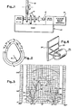
- a conventional cam contour grinding machine 10 includes opposing head and foot stock assemblies which are supported by a base.
- the camshaft 12 supported between the stocks includes a plurality of axially spaced cams 14.
- the stocks are laterally displaceable to axially index the camshaft to sequentially locate each cam in front of the grinding wheel assembly including a grinding wheel 16 which is advanceable in accordance with a predetermined infeed program to effect the desired grinding wheel penetration.
- the stocks are also conventionally selectively rockable to displace the camshaft towards and away from the grinding wheel.
- Camshafts are utilized in internal combustion engines and include a plurality of cams which are associated with each cylinder.
- a camshaft for a gasoline engine has intake and exhaust cams
- a camshaft for a diesel engine has intake, exhaust and injector cams. Since the contour of these cams are different and since the orientation of one set of cams may be different than that of another set, a cam contour grinding machine conventionally includes a corresponding number of master cams (not shown) properly oriented to control the rocking motion for each cam on the camshaft.
- Each cam qenerally includes a nose portion N, a base portion B defined by a radius R, and opposing flank portions F1, F2 which join the nose and base portions.
- the base which extends greater than 180°, is cylindrical relative to the axis of rotation of the camshaft, rotating the camshaft at a constant velocity (V b ) during the period that this portion contacts the grinding wheel will achieve uniform wheel penetration and uniform stock removal.
- V b constant velocity
- the cam is rotated at a velocity of 60 rpm for approximately 210°.
- the cam is rotated at a second velocity (V f ) of 10 rpm along a portion of each flank F1, F2 and at a third velocity (V n ) of 120 rpm around the nose.
- Acceleration (or deceleration) segments A1, A2, A3, A4 interconnect these constant velocity segments.
- An acceleration or deceleration segment includes two basic components; radiused end portions (E1, E2) (E3, E4), E5, E6), (E7, E8) defined by radii (Rl, R2), (R3, R4), (R5, R6), (R7, R8) which tangentially merge into their associated constant velocity segment.
- Such radiused portions may either tangentially merge into each other or they may tangentially interconnect with a linear inclined central portion L1, L2, L3, L4.
- the location where a constant velocity segment of the cam joins an acceleration or decleration segment can.be referred to as a set point (Tl,...T8).
- the set point is preselected from programmed points on the cam contour.
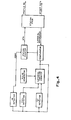
- the circuit for identifying the cam which is to be ground is shown in Figure 4.
- the lateral position of the camshaft is indicated by a Lateral Position Counter driven by a suitable Pulse Generator and the predetermined lateral positions of the camshaft for aligning each cam with the grinding wheel contained in the Station Prom (Programmable read only memory), are compared by a Comparator.
- the Comparator drives a Station Counter which provides the Station Prom with a binary number identifying the cam which is aligned with the grinding wheel.
- the Station Prom issues a profile number defining the type of cam (intake, exhaust or injector, for example) and an offset which, in effect, will reorient the cam to a desired standard orientation.
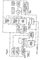
- This data is supplied to the variable speea cam drive circuit ( Figure 5).
- the profile number is supplied to the Selector which selects the set points and velocity profile prom for the cam to be ground.
- the offset data is loaded into the angle position counter by a Program Start signal which occurs once for every cam revolution. An identical program will be repeated for each complete revolution until sufficient stock removal has been removed from all portions of the cam.
- the camshaft is rotatably driven by a stepping motor (Motor Control) which is driven by the clock frequency of the Oscillator divided by the "N" number.
- An oscillator generates a continuous train of pulses at a fixed rate or frequency.
- An individual pulse from this train issued to the stepping motor will drive the stepping motor one pulse and a predetermined number of pulses issued to the stepping motor will effect one complete revolution.
- a divide by "N” circuit defines which pulse in the generated pulse train will be the next pulse to pass therethrough and, hence, what time interval between two successive pulses. Stated differently, a divide by "N” circuit will block any selected number of pulses of the train, following a selected pulse, from issuing to the stepping motor.
- the Angle Position Counter will be updated by each pulse. If the grinding wheel is contacting a constant velocity segment, the Motor Control Prom will generate a count inhibit (CI) signal which will continue the status of the Motor Control. The address of the divide by N number will, accordingly, remain the same along a constant velocity segment with the stepping motor running at that constant velocity.
- the Motor Control Prom When a specific set point is reached, the Motor Control Prom will generate a signal directing the velocity control to either up count or down count, and will delete the count inhibit signal.
- tne set point locates tne point on the velocity profile where an acceleration/ deceleration segment joins a constant velocity segment.
- the time interval between each pulse will be constant (the N number will not change).
- the time interval between each successive,pulse generated during a change of velocity will be selected to conform to.the profile of the preselected acceleration/deceleration segment.
- the address will be changed for each successive count throughout the duration of an acceleration/deceleration segment to vary the N number for each successive pulse. Accordingly, a different pulse rate will be established for every step of the stepping motor when proceeding along an acceleration/deceleration segment.
- the time interval between successive pulses will be increased (the number of pulses blocked between issued pulses will have to be increased) and this will be effected by changing the N number of the divide by "N" circuit.
- Each Velocity Profile Prom will contain addressable N numbers defining each of the plurality of acceleration/deceleration velocity profile segments present in the velocity profile for a specified cam. Where the cam is symmetrical, the count direction may be programmed to reverse so that the acceleration/ deceleration segment on the back side of the cam will be the mirror image of the acceleration/deceleration segment on the front side.
- a synchronization signal will confirm that a velocity profile is commencing at the same point on the cam for each revolution.
- a stepping motor is conventionally utilized as a positioning motor and not as a driving motor as is the case herein.
- the repetitive acceleration and deceleration of the stepping motor as a drive motor under the disclosed duty cycle raises its temperature beyond intended limits.
- a heat sink here in the form of a passive cooling system structure is provided for the motor ( Figure 6).
- the cooling system includes a jacket 20 which encloses the motor and absorbs heat generated by the motor, a plurality of heat pipes 22 normally containing freon and a heat dissipating structure, here in the form of a finned plate 24.
Landscapes
- Engineering & Computer Science (AREA)
- Mechanical Engineering (AREA)
- Human Computer Interaction (AREA)
- Manufacturing & Machinery (AREA)
- Physics & Mathematics (AREA)
- General Physics & Mathematics (AREA)
- Automation & Control Theory (AREA)
- Grinding And Polishing Of Tertiary Curved Surfaces And Surfaces With Complex Shapes (AREA)
Applications Claiming Priority (2)
| Application Number | Priority Date | Filing Date | Title |
|---|---|---|---|
| US06/308,232 US4402161A (en) | 1981-10-02 | 1981-10-02 | Cylindrical grinding machine |
| US308232 | 1994-09-19 |
Publications (2)
| Publication Number | Publication Date |
|---|---|
| EP0076590A2 true EP0076590A2 (fr) | 1983-04-13 |
| EP0076590A3 EP0076590A3 (fr) | 1984-11-07 |
Family
ID=23193121
Family Applications (1)
| Application Number | Title | Priority Date | Filing Date |
|---|---|---|---|
| EP82304959A Ceased EP0076590A3 (fr) | 1981-10-02 | 1982-09-21 | Machine de meulage cylindrique |
Country Status (4)
| Country | Link |
|---|---|
| US (1) | US4402161A (fr) |
| EP (1) | EP0076590A3 (fr) |
| JP (1) | JPS5871057A (fr) |
| CA (1) | CA1192750A (fr) |
Cited By (5)
| Publication number | Priority date | Publication date | Assignee | Title |
|---|---|---|---|---|
| FR2547930A1 (fr) * | 1983-05-06 | 1984-12-28 | Helbrecht Otto | Rectifieuse a commande numerique pour les bords de verres de lunettes |
| FR2566693A1 (fr) * | 1983-05-06 | 1986-01-03 | Helbrecht Otto | Rectifieuse a commande numerique pour les bords de verres de lunettes |
| EP0258641A3 (en) * | 1986-08-01 | 1988-12-14 | Litton Industrial Automation Systems, Inc. | Velocity servo with position error correction |
| DE3814124A1 (de) * | 1988-04-27 | 1989-11-09 | Fortuna Werke Maschf Ag | Verfahren zum schleifen von nocken einer nockenscheibe |
| EP0342528A3 (fr) * | 1988-05-19 | 1991-04-17 | Fortuna-Werke Maschinenfabrik GmbH | Méthode de rectification de cames d'arbre à cames |
Families Citing this family (3)
| Publication number | Priority date | Publication date | Assignee | Title |
|---|---|---|---|---|
| GB2283192B (en) * | 1993-10-20 | 1997-07-16 | Western Atlas Uk Ltd | Improvements in and relating to grinding machines |
| US6582166B1 (en) | 1999-10-22 | 2003-06-24 | Gerber Scientific Products, Inc. | Method of compensating for cutter deflection |
| JP6949896B2 (ja) * | 2019-03-27 | 2021-10-13 | ファナック株式会社 | 砥石選定装置及び砥石選定方法 |
Family Cites Families (11)
| Publication number | Priority date | Publication date | Assignee | Title |
|---|---|---|---|---|
| US3716949A (en) * | 1970-06-12 | 1973-02-20 | Landis Tool Co | Feed rate and positioning control system for a machine tool |
| US3701220A (en) * | 1970-08-03 | 1972-10-31 | Norton Co | Electric feed for machine element |
| JPS5421598B2 (fr) * | 1972-12-02 | 1979-07-31 | ||
| JPS5339590A (en) * | 1976-09-23 | 1978-04-11 | Toyoda Mach Works Ltd | Cam grinder |
| US4102082A (en) * | 1977-02-22 | 1978-07-25 | Mitsubishi Jukogyo Kabushiki Kaisha | Cam grinding apparatus with means to maintain the grinding speed constant |
| US4197679A (en) * | 1977-04-15 | 1980-04-15 | Ito & Okamoto, Esq. | Method for controlling the rotational speed of a rotary body |
| GB1596635A (en) * | 1977-07-26 | 1981-08-26 | Newall Eng | Cam machining |
| JPS5467280A (en) * | 1977-11-08 | 1979-05-30 | Toyoda Mach Works Ltd | Numerical control unit for controlling the processing of a nonround work |
| JPS555222A (en) * | 1978-06-20 | 1980-01-16 | Toyoda Mach Works Ltd | Revolving speed controller for work in cam grinder |
| DE2832931A1 (de) * | 1978-07-27 | 1980-02-07 | Daimler Benz Ag | Steuersystem zum kopierschleifen |
| FR2460182A1 (fr) * | 1979-06-29 | 1981-01-23 | Gendron Sa | Dispositif permettant d'usiner des cames avec precision, et avec une vitesse de coupe constante |
-
1981
- 1981-10-02 US US06/308,232 patent/US4402161A/en not_active Expired - Lifetime
-
1982
- 1982-09-14 CA CA000411380A patent/CA1192750A/fr not_active Expired
- 1982-09-21 EP EP82304959A patent/EP0076590A3/fr not_active Ceased
- 1982-10-02 JP JP57173809A patent/JPS5871057A/ja active Pending
Cited By (5)
| Publication number | Priority date | Publication date | Assignee | Title |
|---|---|---|---|---|
| FR2547930A1 (fr) * | 1983-05-06 | 1984-12-28 | Helbrecht Otto | Rectifieuse a commande numerique pour les bords de verres de lunettes |
| FR2566693A1 (fr) * | 1983-05-06 | 1986-01-03 | Helbrecht Otto | Rectifieuse a commande numerique pour les bords de verres de lunettes |
| EP0258641A3 (en) * | 1986-08-01 | 1988-12-14 | Litton Industrial Automation Systems, Inc. | Velocity servo with position error correction |
| DE3814124A1 (de) * | 1988-04-27 | 1989-11-09 | Fortuna Werke Maschf Ag | Verfahren zum schleifen von nocken einer nockenscheibe |
| EP0342528A3 (fr) * | 1988-05-19 | 1991-04-17 | Fortuna-Werke Maschinenfabrik GmbH | Méthode de rectification de cames d'arbre à cames |
Also Published As
| Publication number | Publication date |
|---|---|
| JPS5871057A (ja) | 1983-04-27 |
| CA1192750A (fr) | 1985-09-03 |
| EP0076590A3 (fr) | 1984-11-07 |
| US4402161A (en) | 1983-09-06 |
Similar Documents
| Publication | Publication Date | Title |
|---|---|---|
| EP0085225B1 (fr) | Machine à meuler cylindrique | |
| US4402161A (en) | Cylindrical grinding machine | |
| US4312685A (en) | Surface hardening of cams of motor-vehicle camshafts | |
| US5392566A (en) | Process and device for numerically controlled grinding of cams of a camshaft | |
| US3344559A (en) | Cam grinding machine by means of numerical control | |
| CA2043156C (fr) | Dispositif de detection de la position angulaire d'un vilebrequin | |
| WO1983004283A1 (fr) | Detecteur | |
| US4366543A (en) | Method and apparatus for the out-of-round shaping of workpieces | |
| US5472368A (en) | Method of and machine for grinding cams | |
| EP0405811A1 (fr) | Procédé et machine de finissage de commutateur | |
| US4343114A (en) | Apparatus for machining cams at a constant cutting speed | |
| US7435164B2 (en) | Grinding method and grinding device | |
| US4726338A (en) | Device for controlling internal combustion engines | |
| CA1200081A (fr) | Methode et machine d'usinage des vilebrequins | |
| JP2541597B2 (ja) | 内燃機関の制御のための装置 | |
| JPH0632894B2 (ja) | カム研削装置 | |
| US20060166604A1 (en) | Process and apparatus for grinding work for non-circular rotor, as well as camshaft | |
| GB2116463A (en) | Process and apparatus for grinding the surface of a cam | |
| EP0741630B1 (fr) | Ameliorations du meulage ou s'y rapportant | |
| JPS55125973A (en) | Cam grinding machine with numerical control | |
| SU484071A1 (ru) | Способ отделочной обработки | |
| SU1502282A1 (ru) | Устройство дл охлаждени и очистки шлифовального круга | |
| JPS6368350A (ja) | カム研削盤 | |
| SU1278183A1 (ru) | Способ заточки прецизионных черв чных фрез | |
| SU1252134A1 (ru) | Способ шлифовани фасонных поверхностей деталей |
Legal Events
| Date | Code | Title | Description |
|---|---|---|---|
| PUAI | Public reference made under article 153(3) epc to a published international application that has entered the european phase |
Free format text: ORIGINAL CODE: 0009012 |
|
| AK | Designated contracting states |
Designated state(s): DE FR GB IT |
|
| PUAL | Search report despatched |
Free format text: ORIGINAL CODE: 0009013 |
|
| AK | Designated contracting states |
Designated state(s): DE FR GB IT |
|
| 17P | Request for examination filed |
Effective date: 19850102 |
|
| 17Q | First examination report despatched |
Effective date: 19860219 |
|
| STAA | Information on the status of an ep patent application or granted ep patent |
Free format text: STATUS: THE APPLICATION HAS BEEN REFUSED |
|
| 18R | Application refused |
Effective date: 19871017 |
|
| RIN1 | Information on inventor provided before grant (corrected) |
Inventor name: HARREL, JACK D. Inventor name: PRICE, RALPH E. |