EP0076644A2 - Procédé et dispositif pour séparer deux objets - Google Patents
Procédé et dispositif pour séparer deux objets Download PDFInfo
- Publication number
- EP0076644A2 EP0076644A2 EP82305177A EP82305177A EP0076644A2 EP 0076644 A2 EP0076644 A2 EP 0076644A2 EP 82305177 A EP82305177 A EP 82305177A EP 82305177 A EP82305177 A EP 82305177A EP 0076644 A2 EP0076644 A2 EP 0076644A2
- Authority
- EP
- European Patent Office
- Prior art keywords
- members
- apart
- items
- open
- facilitate
- Prior art date
- Legal status (The legal status is an assumption and is not a legal conclusion. Google has not performed a legal analysis and makes no representation as to the accuracy of the status listed.)
- Withdrawn
Links
Images


Classifications
-
- A—HUMAN NECESSITIES
- A62—LIFE-SAVING; FIRE-FIGHTING
- A62B—DEVICES, APPARATUS OR METHODS FOR LIFE-SAVING
- A62B3/00—Devices or single parts for facilitating escape from buildings or the like, e.g. protection shields, protection screens; Portable devices for preventing smoke penetrating into distinct parts of buildings
- A62B3/005—Rescue tools with forcing action
Definitions
- This invention relates to a method of and means for prising two items apart and more particularly but not exclusively to a method useful in the event of a motor accident wherein a door of a vehicle involved in the accident is damaged and thus jammed closed. In this event, it is not possible to open the door by operating the usual door latch mechanism.
- one item may comprise the damaged door, and the other item a door post or other part of the vehicle.
- the first is to use a prising tool such as a crowbar, the shaped end of which is forced into a space between the door and door post and the bar manipulated as a lever to prise the door open.
- This method has the disadvantage that great manual effort is required and often it is not possible to exert sufficient effort to open a door in which case the second method is adopted.
- the second method involves cutting the door open utilising an oxyacetelene cutting torch.
- the disadvantages of this method include a risk of explosion and fire due to the presence of a volatile fluid and that toxic fumes and heat are produced as a result of the method which are obviously undesirable due to the presence of a trapped occupant of the vehicle.
- a method of prising two items apart using a device comprising first and second rigid members pivotally connected for relative pivotal movement about an axis transverse to the members, said method comprising the steps of inserting one end of both of the members closed together between said items to be prised apart, relatively pivoting said first and second members thereby causing said one ends to open to prise said items apart.
- said members are pivoted using a fluid operated ram such as a hydraulic or pneumatic ram or other power means between said other ends.
- a fluid operated ram such as a hydraulic or pneumatic ram or other power means between said other ends.
- the invention provides a method using a power tool which is capable of exerting great force to prise the items apart, and said method does not produce heat or toxic fumes.
- a device for use in the method according to the first aspect of the invention comprising first and second rigid members, means pivotally connecting said members for pivotal movement about an axis transverse to the members, one end of each of the members being adapted to be inserted closed together between said two items to be prised apart, and the members being adapted to be pivoted by power means to cause said one ends to open to prise said items apart.
- the members are pivoted intermediate their ends and said one ends are moved apart by moving the other ends of the members apart, the power means acting on said other ends.
- the members are pivoted at their other ends and the power means acts between the members intermediate their ends.
- first and second members may be cranked in the region of the pivot, whereby when said one ends are closed together, the other ends are a first distance apart, said other ends being movable further apart to a second distance wherein said one ends are open.
- first and second members are possible.
- the extent of movement of said one ends may be governed by the construction of the fluid-operated ram or other power means, although other restraining means may be provided if required.
- Said first member may comprise two elements of similar configuration rigidly spaced from one another, and said second member may comprise a single element which is movable between the two elements of the first member. This arrangement has been found to be particularly useful as the resulting device is very strong and rigid.
- Said one ends of said first and second members may be provided with a pointed tip to facilitate inserting said ends between the two items to be prised apart. It will be appreciated that if the device is inserted with great force, that the pointed tip may deform the edges of the items to increase the proportion of said one ends of the device which are receivable between said items, to increase leverage.
- each of the first and second members are provided with toothed jaws attached to or integral with the respective members which jaws may engage the items and facilitate gripping of the items.
- the jaws may be made of hardened steel.
- said elements may be held rigidly apart adjacent said one end by one of said jaws, and also if necessary, adjacent said other end by a spacer such as a metal block.
- the device may conveniently be provided with a holding means which means may not only facilitate holding the device during operation, but also provide a rigid grip to facilitate inserting the one ends of the members of the device between said items, with great force.
- the fluid-operated ram comprises a hydraulic ram and the method may include operatively coupling said device to a hydraulic power pack which provides hydraulic fluid under pressure to the ram.
- the pack is preferably portable and provided with a manual pump or the pump may be operated by an internal combustion engine or electric motor or the like.
- the power pack may be provided on an emergency tender vehicle. such as a fire engine.
- such a fluid-operated ram may be capable of moving said other ends of the members of the device apart with great force, for example a force of up to 16 tons, so as to provide a substantial levering force to prise said items apart.
- the method is particularly useful for prising doors open and prising apart other parts of motor cars or vehicles which have been crushed or otherwise damaged for example, in an accident, either to facilitate rescue of an occupant of the vehicle, or to facilitate repairs to the vehicle although it can be used to prise any two items apart.
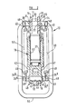
- a device 10 for use in a method of prising two items apart comprising first 11 and second 12 cranked members pivotally connected by a pivot pin 13 intermediate the ends thereof.
- One end 14 of each of the members 11, 12 are shown closed together whilst the other ends 15, 16 are a first distance d1 apart.
- the other ends 15, 16 of each of the members 11, 12 are inter-connected by a hydraulic ram 18.
- the first member 11 comprises a pair of elements 19, 20 rigidly spaced apart adjacent said one ends 14 by a toothed jaw 21 comprising a plate interconnecting the elements 19, 20 at their edges, and adjacent the other end 15 by a block 22 which is welded, or otherwise secured to and between the elements 19, 20.
- the second member 12 comprises a single element and is pivoted for movement in a plane between the elements 19, 20 of the first member 11.
- the one end 14 of the member 12 is received between the one ends 14 of the elements 19, 20 of the member 11.
- the member 12 is also provided with a toothed jaw 23, the jaws 21, 23 being made of hardened steel and secured in position by welding or as desired, to the respective members 11, 12.
- the one ends 14 of the members 11, 12 and untoothed parts 21a, 23a of the jaws 21, 23 provide a pointed and sharpened tip 24 for use as hereinafter described.
- the pivot pin 13 comprises a hollow shank 25 having a flanged head at one end.
- the shank 25 extends through and from the members 11, 12, a washer 28 being received on the extending end of the shank 25 and retained thereon by means of a transversely extending split pin 29 which is received in a transversely extending passage 30 in the extending end of the shank 25.
- the said other ends 15, 16 of the members 11, 12 of the device are provided with apertures, the first member 11 having aligned apertures 31 in the elements 19, 20.
- the ram 18 has a piston 32 the outward end of the piston 32 being flattened and received between the two elements 19, 20 and also having an aperture 33 aligned with apertures 31 of the elements 19, 20 through which a pivot pin 34 passes.
- the pin 34 extends from either side of the member 11 and is located in the position shown by means of washers 35 and split pins 36 which extend through transverse apertures 37 of the pin 34.
- the ram 18 also comprises a cylinder 37 in which the piston 32 is slidable, the cylinder 37 having a bifurcated end 40 between the limbs 41, 42 of which the other end 16 of the second member 12 is received.
- the limbs 41, 42 of the end 40 are provided with aligned apertures 43, and the end 16 of the second member with an aperture 44 also aligned with apertures 43, through which apertures 43, 44 a further pivot pin 45 extends.
- the pin 45 is also located in position by further washers 35a, split pins 36a which pins extend through transverse apertures 37a in the pin 45.
- Adjacent each projecting end of each pin 34, 45, grooves 48 are provided in which the end coils 49 of springs 50, 51 are received to urge the other ends 15, 16 of the members 11, 12 together.
- the ram 18 has a chamber 52 in the cylinder 37, with which a nozzle 53 communicates, from which nozzle hydraulic fluid under pressure may be fed from a hydraulic power pack (not shown) to which it is connected by a flexible pipe P1 into the chamber 52 to urge the piston 32 from the cylinder 37 against the force of springs 50, 51 to move the other ends 15, 16 of the members 11, 12 apart to a second distance indicated by arrow d2.
- the first member 11 has welded thereto at 54 a handle 55.
- the handle 55 comprises a substantially rectangular loop and provides a rigid holding means for the use of the device 10.
- the pointed tip 24 is inserted with the one ends 14 of the device 10 closed together as shown in full lines , in a space between the jammed door and a door post or other part of the vehicle, until the jaws 21, 23 grip the edges of the door and post. This may be done with some force as the handle 55 provides a rigid support.
- the hydraulic ram 18 is then actuated to move the ends 15, 16 of the members 11, 12 apart, and thus the members 11, 12 will pivot about pivot pin 13 in parallel planes and the ends 14 will open.
- the toothed jaws 41, 43 will grip the edges of the door and post and the door will be prised open.
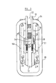
- FIG. 4 and 5 there is illustrated a modification in which the device is as described with reference to the preceding Figures except as hereinafter to be described.
- this modification instead of the handles 55 described hereinbefore there are provided handles 55a welded to the first member 11a at 54a and 54b.
- the springs 50 instead of the springs 50, 51 there are provided springs. 50a, 51a hooked onto the horizontally extending parts 55b of the handles 55a at their upper ends and to pins 60a welded to the second member 12a at their lower ends.
- the members 11, 12 need not be of the configuration shown but many other configurations are possible.
- the ram 18 need not comprise a hydraulic ram, but a pneumatic ram or other power means to move the ends 15, 16 apart may be provided.
- the members 11, 12 are pivoted intermediate their ends by a power means 18 which acts between the ends 15, 16, if desired, by suitable modification of the configuration of the members 11, 12, the members 11, 12 may be pivoted at their ends 15, l6 and the power means l8 may act intermediate the ends of the members, for example, between the members.
- the device may be used to puncture a panel or other item due to the pointed tip 24.
- the two items will comprise the edges of the puncture and the panel may be torn open by the method and device hereinbefore described.
Landscapes
- Health & Medical Sciences (AREA)
- General Health & Medical Sciences (AREA)
- Business, Economics & Management (AREA)
- Emergency Management (AREA)
- Vehicle Cleaning, Maintenance, Repair, Refitting, And Outriggers (AREA)
- Straightening Metal Sheet-Like Bodies (AREA)
- Automobile Manufacture Line, Endless Track Vehicle, Trailer (AREA)
- On-Site Construction Work That Accompanies The Preparation And Application Of Concrete (AREA)
- Transmission Devices (AREA)
Applications Claiming Priority (2)
| Application Number | Priority Date | Filing Date | Title |
|---|---|---|---|
| GB8129782 | 1981-10-02 | ||
| GB08129782A GB2111421A (en) | 1981-10-02 | 1981-10-02 | Prising apart two items |
Publications (2)
| Publication Number | Publication Date |
|---|---|
| EP0076644A2 true EP0076644A2 (fr) | 1983-04-13 |
| EP0076644A3 EP0076644A3 (fr) | 1984-08-01 |
Family
ID=10524897
Family Applications (1)
| Application Number | Title | Priority Date | Filing Date |
|---|---|---|---|
| EP82305177A Withdrawn EP0076644A3 (fr) | 1981-10-02 | 1982-09-29 | Procédé et dispositif pour séparer deux objets |
Country Status (2)
| Country | Link |
|---|---|
| EP (1) | EP0076644A3 (fr) |
| GB (1) | GB2111421A (fr) |
Cited By (2)
| Publication number | Priority date | Publication date | Assignee | Title |
|---|---|---|---|---|
| EP0437651A1 (fr) * | 1988-04-22 | 1991-07-24 | Robert F. Ganley | Outil de sauvetage avec entraînement à vis |
| US20100025647A1 (en) * | 2006-11-08 | 2010-02-04 | Weber-Hydraulik Gmbh | Rescue device with spreading mechanism |
Families Citing this family (1)
| Publication number | Priority date | Publication date | Assignee | Title |
|---|---|---|---|---|
| DE9215062U1 (de) * | 1992-11-05 | 1992-12-24 | FAG Kugelfischer Georg Schäfer KGaA, 8720 Schweinfurt | Spreizgerät mit auswechselbaren Spreizbacken |
Family Cites Families (4)
| Publication number | Priority date | Publication date | Assignee | Title |
|---|---|---|---|---|
| FR1578862A (fr) * | 1968-04-16 | 1969-08-22 | ||
| US3819153A (en) * | 1972-04-26 | 1974-06-25 | Hurst Performance | Rescue tool |
| US4130270A (en) * | 1977-10-18 | 1978-12-19 | Sandvik Aktiebolag | Wedge arrangement |
| FR2464915B1 (fr) * | 1979-09-07 | 1986-04-18 | Cardona Georges | Perfectionnements apportes aux appareils utilises notamment pour la desincarceration des occupants d'un vehicule accidente |
-
1981
- 1981-10-02 GB GB08129782A patent/GB2111421A/en not_active Withdrawn
-
1982
- 1982-09-29 EP EP82305177A patent/EP0076644A3/fr not_active Withdrawn
Cited By (3)
| Publication number | Priority date | Publication date | Assignee | Title |
|---|---|---|---|---|
| EP0437651A1 (fr) * | 1988-04-22 | 1991-07-24 | Robert F. Ganley | Outil de sauvetage avec entraînement à vis |
| US20100025647A1 (en) * | 2006-11-08 | 2010-02-04 | Weber-Hydraulik Gmbh | Rescue device with spreading mechanism |
| US8505877B2 (en) * | 2006-11-08 | 2013-08-13 | Weber-Hydraulik Gmbh | Rescue device with spreading mechanism |
Also Published As
| Publication number | Publication date |
|---|---|
| EP0076644A3 (fr) | 1984-08-01 |
| GB2111421A (en) | 1983-07-06 |
Similar Documents
| Publication | Publication Date | Title |
|---|---|---|
| US5125158A (en) | Hand manipulated portable cutting and shearing tool with spreader adaptors | |
| US4392263A (en) | Portable rescue tool | |
| US3819153A (en) | Rescue tool | |
| US4973028A (en) | Rescue tool jaw | |
| US4506445A (en) | Rescue cutter tool | |
| US5711078A (en) | Portable emergency rescue cutting and crimping tool | |
| US6244568B1 (en) | Rescue spreading tool | |
| CN110038236B (zh) | 液压工作仪器 | |
| US3276237A (en) | Apparatus for straightening automobile bodies | |
| US3275172A (en) | Wrecking and loading tool for use with a back hoe | |
| US2932244A (en) | Portable hydraulic baling machine | |
| DE19737133A1 (de) | Fluidbetätigte Vorrichtung zum Aufbrechen und für andere Zwecke | |
| EP2310154A1 (fr) | Outil de sauvetage hydraulique | |
| US5054180A (en) | Hinge pin tool | |
| EP0683271A1 (fr) | Arrangement de poteau | |
| US3577881A (en) | Portable highway crash rescue unit | |
| US4062117A (en) | Rescue tool means | |
| GB2111421A (en) | Prising apart two items | |
| US3710655A (en) | Battering apparatus for opening jammed automobile doors | |
| US5425260A (en) | Accident rescue tool | |
| US5463862A (en) | Roller chain breaker | |
| US6990781B2 (en) | Decking assembly with an interlocking seam structure | |
| US4171616A (en) | Hydraulic emergency hand tools | |
| US3707179A (en) | Tire removing device for breaking the bead of farm tractor tires to facilitate removal from the rim | |
| CN110561470A (zh) | 抱顶式翻车机械手及操作方法 |
Legal Events
| Date | Code | Title | Description |
|---|---|---|---|
| PUAI | Public reference made under article 153(3) epc to a published international application that has entered the european phase |
Free format text: ORIGINAL CODE: 0009012 |
|
| AK | Designated contracting states |
Designated state(s): AT BE CH DE FR GB IT LI LU NL SE |
|
| PUAL | Search report despatched |
Free format text: ORIGINAL CODE: 0009013 |
|
| AK | Designated contracting states |
Designated state(s): AT BE CH DE FR GB IT LI LU NL SE |
|
| STAA | Information on the status of an ep patent application or granted ep patent |
Free format text: STATUS: THE APPLICATION IS DEEMED TO BE WITHDRAWN |
|
| 18D | Application deemed to be withdrawn |
Effective date: 19850402 |
|
| RIN1 | Information on inventor provided before grant (corrected) |
Inventor name: BARRON, MICHAEL JOSEPH Inventor name: GRIFFITHS, REGINALD Inventor name: EDGE, ROBERT WILLIAM |