EP0076657A2 - Boîtier pour appareil électrique - Google Patents
Boîtier pour appareil électrique Download PDFInfo
- Publication number
- EP0076657A2 EP0076657A2 EP82305226A EP82305226A EP0076657A2 EP 0076657 A2 EP0076657 A2 EP 0076657A2 EP 82305226 A EP82305226 A EP 82305226A EP 82305226 A EP82305226 A EP 82305226A EP 0076657 A2 EP0076657 A2 EP 0076657A2
- Authority
- EP
- European Patent Office
- Prior art keywords
- modular
- housing
- electrical apparatus
- bus bars
- opposite faces
- Prior art date
- Legal status (The legal status is an assumption and is not a legal conclusion. Google has not performed a legal analysis and makes no representation as to the accuracy of the status listed.)
- Withdrawn
Links
Images

Classifications
-
- H—ELECTRICITY
- H05—ELECTRIC TECHNIQUES NOT OTHERWISE PROVIDED FOR
- H05K—PRINTED CIRCUITS; CASINGS OR CONSTRUCTIONAL DETAILS OF ELECTRIC APPARATUS; MANUFACTURE OF ASSEMBLAGES OF ELECTRICAL COMPONENTS
- H05K5/00—Casings, cabinets or drawers for electric apparatus
- H05K5/30—Side-by-side or stacked arrangements
Definitions
- the invention relates to electrical apparatus and more particularly, but not exclusively, to electronic audio and audio-visual apparatus of the general nature of amplifiers, pre-amplifiers, power supplies, filters, equalisers, radio tuners and television tuners. It is thought that the invention may also be applicable to electronic apparatus of the nature of computers and calculators.
- electrical apparatus comprising a modular housing having a pair of opposite .faces adapted to engage further similar modular housings, the modular housing having at least one bus bar extending between the opposite faces and arranged for connection to the corresponding bus bars of adjacent modular housings whereby the modular housings can be electrically interconnected.
- At least one series of bus bars extends between the opposite faces of the housing, each of which is arranged for direct electrical connection to the corresponding bus bars of the adjacent modular housings.
- one end of each bus bar is terminated by a pin connector and the other end of each bus bar is terminated by a socket connector.
- the apparatus comprises means for mechanically connecting the modular housings together independently of the bus bars.
- the means for mechanically connecting the modular housings together may comprise one or more (preferably a pair) of tie rods extending between the said opposite faces of the housing, the tie rods being arranged for connection to the corresponding tie rod of adjacent modular housings.
- said modular housing is generally rectangular in shape and comprises a front face which carries any necessary switches and visual indicators, a pair of side faces which form the said opposite faces and a rear face which carries any appropriate signal source inputs, power outputs and power outlets, the arrangement being such that the top of the modular housing projects over the rear face to shield the inputs and outputs.
- a flap may be hinged to the front face of the housing and arranged to cover at least one control on the front face.
- the hinged flap covers substantially the whole of the front face of the housing and is arranged to actuate a switch which energises the electrical circuitry associated with the modular housing.
- each module whether it is of the signal conditioning, signal processing or output kind, is complete in the sense that it carries all of the input connections, signal boosting circuitry and control means for that particular signal. It is usual with audio apparatus to feed a power amplifier from several sources, and it is envisaged that input or signal conditioning modules such as a magnetic tape module, a radio tuner module and a module for conditioning the output from a record pick-up cartridge each provided with its own inputs on the rear face and with its own controls on the front face, will be coupled together side by side, and electronically connected as appropriate by bus bars extending through the input modules to the power amplifier module or modules.
- input or signal conditioning modules such as a magnetic tape module, a radio tuner module and a module for conditioning the output from a record pick-up cartridge each provided with its own inputs on the rear face and with its own controls on the front face, will be coupled together side by side, and electronically connected as appropriate by bus bars extending through the input modules to the power amplifier module or modules.
- one or more tone control or the like signal processing modules could be provided if desired side by side with the input and output modules and connected to the other modules by the bus bars.
- the pin and socket connections on the modules are arranged such that it is not possible to connect the modules together in an inappropriate sequence. It would be possible to provide a bridge piece which is coupled to one end of the series of modules by pin and socket connections and which serves the function of electrically connecting as appropriate the various bus bars, but we prefer to accomplish the connections electronically.
- the bus bars may be arranged in two or more spaced series in each module, for example, low level signals can be carried by one series of bus bars while high voltage signals are carried by a further set of bus bars, but alternatively the bus bars may be arranged in a single row.
- a short flexible bus bar connector arranged to be connected to the bus bars of the upper and lower modules.
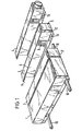
- FIG. 1 a modular housing system for electrical apparatus by means of which the housings of various pieces of apparatus for example audio or audio-visual apparatus may be connected together directly without the need for interconnecting cables.
- FIGs 1 and 2 show four such modules referenced 1 to 4 respectively.
- module 1 is a power supply
- module 2 is a switchable tone control
- module 3 is a moving coil input
- module 4 is a volume control, all for audio apparatus.
- Each module is generally rectangular in shape and comprises a front face formed with controls for actuating that module, a rear face which carries as appropriate input connections from associated equipment such as a record deck or tape recorder, or power inputs or power outputs and a pair of side faces arranged to engage the side faces of the adjacent modules.
- module 3 is indicated by reference numeral 5 and its side faces are indicated by reference numerals 6 and 7 respectively.
- the modules each have a plurality of bus bars extending therethrough by means of which the modules are electrically interconnected and the bus bars are terminated at one end by pins 8 extending from the side face 7 of the module 3 and at the other end by sockets 9 on the other side 6 of the module 3.
- the modules 1, 2 and 4 are similarly provided with bus bars extending therethrough which are terminated on one side with pins and on the other side with sockets. In this manner the modules can be connected together directly side by side.
- the modules are also interconnected mechanically by means of a pair of tie rods 10 so that the modules are firmly interconnected independently of the pin and socket connectors.
- the tie bars 10 extend through apertures 15 in the respective modules.
- the pre-amplifier module 4 is formed on its front face with a rotary volume control knob 11.
- the modules 2 and 3 have hinged flaps 12 which in their closed position cover the front faces of the respective modules, which flaps are arranged to actuate switches when in the closed position shown in Fig. 1 and when touched by means of which the electrical circuitry of the respective modules are brought into operation.
- the hinged covers 12 When the hinged covers 12 are pivoted into the substantially horizontal position shown in Figure 2 they expose secondary controls for the circuitry of the modules in the form of push-buttons 13.
- the top surface is extended as shown at 14 to over-hang the rear face of the modules. This over-hanging portion is intended to protect the input and output connections on the rear face of the modules.
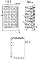
- the socket connector block 9 for receiving the corresponding pins 8 of the adjacent module is formed with a forward extension 16 which carries conical guide apertures 17 one of which is associated with each respective socket connector 18 so that the pins 8 are guided into position in the connector block.
- the pins and corresponding sockets are disposed in four rows each containing six sockets. Therefore the modules each have twenty four bus bars for interconnection.
- Figure 5 shows a cross section of a cap arranged as a press fit over the pins 8 of the bus bar connectors to protect the pins against accidental damage.
Landscapes
- Engineering & Computer Science (AREA)
- Microelectronics & Electronic Packaging (AREA)
- Casings For Electric Apparatus (AREA)
- Details Of Connecting Devices For Male And Female Coupling (AREA)
Applications Claiming Priority (2)
| Application Number | Priority Date | Filing Date | Title |
|---|---|---|---|
| GB8129944 | 1981-10-03 | ||
| GB8129944 | 1981-10-03 |
Publications (2)
| Publication Number | Publication Date |
|---|---|
| EP0076657A2 true EP0076657A2 (fr) | 1983-04-13 |
| EP0076657A3 EP0076657A3 (fr) | 1983-06-08 |
Family
ID=10524942
Family Applications (1)
| Application Number | Title | Priority Date | Filing Date |
|---|---|---|---|
| EP82305226A Withdrawn EP0076657A3 (fr) | 1981-10-03 | 1982-09-30 | Boítier pour appareil électrique |
Country Status (1)
| Country | Link |
|---|---|
| EP (1) | EP0076657A3 (fr) |
Cited By (11)
| Publication number | Priority date | Publication date | Assignee | Title |
|---|---|---|---|---|
| FR2511791A1 (fr) * | 1981-08-24 | 1983-02-25 | Sony Corp | Appareil electronique a usage personnel d'un faible volume comportant au moins une unite de traitement supplementaire |
| GB2148056A (en) * | 1983-09-30 | 1985-05-22 | Matsushita Electric Works Ltd | Expandable modular sequence control system |
| EP0132152A3 (en) * | 1983-07-18 | 1986-04-02 | Data General Corporation | Modular computer system |
| GB2170656A (en) * | 1983-12-23 | 1986-08-06 | Marconi Co Ltd | Electric circuit assemblies |
| US4605276A (en) * | 1983-03-30 | 1986-08-12 | E. I. Du Pont De Nemours And Company | Two row coaxial cable connector |
| GB2196798A (en) * | 1986-10-27 | 1988-05-05 | Gen Electric Plc | Housing arrangements for electrical/or electronic equipment |
| FR2612358A1 (fr) * | 1986-12-17 | 1988-09-16 | Aerospatiale | Dispositif electronique constitue d'une pluralite de modules alignes et juxtaposes |
| DE3838403A1 (de) * | 1988-11-12 | 1990-05-17 | Asea Brown Boveri | Elektronisches geraet mit mindestens einem anschlussfeld |
| WO1996000377A1 (fr) * | 1994-06-24 | 1996-01-04 | Peter Christen | Systeme de pesee a base de modules electroniques combinables entre eux |
| WO1999049709A1 (fr) * | 1998-03-24 | 1999-09-30 | Honeywell Control Systems Ltd. | Appareil de commande |
| US8105108B2 (en) | 2009-09-17 | 2012-01-31 | Matthew Leigh Vroom | Docking station for portable electronics with voids for connector pass-through and integral connector fastener |
Family Cites Families (5)
| Publication number | Priority date | Publication date | Assignee | Title |
|---|---|---|---|---|
| US2760122A (en) * | 1953-06-01 | 1956-08-21 | Rca Corp | Communication equipment |
| GB1451323A (en) * | 1973-01-11 | 1976-09-29 | Wragg C P | Audio mixing equipment |
| DE2601892A1 (de) * | 1976-01-20 | 1977-07-21 | Wolfgang Ing Grad Kuhn | Elektronic - heim center |
| US4164362A (en) * | 1977-03-11 | 1979-08-14 | Amp Incorporated | Modular card cage with multiple power bus bar means |
| DE3003817A1 (de) * | 1980-02-02 | 1981-08-06 | Wega Elektronik GmbH, 5000 Köln | Modulare stereo-hifi-anlage |
-
1982
- 1982-09-30 EP EP82305226A patent/EP0076657A3/fr not_active Withdrawn
Cited By (12)
| Publication number | Priority date | Publication date | Assignee | Title |
|---|---|---|---|---|
| FR2511791A1 (fr) * | 1981-08-24 | 1983-02-25 | Sony Corp | Appareil electronique a usage personnel d'un faible volume comportant au moins une unite de traitement supplementaire |
| US4605276A (en) * | 1983-03-30 | 1986-08-12 | E. I. Du Pont De Nemours And Company | Two row coaxial cable connector |
| EP0132152A3 (en) * | 1983-07-18 | 1986-04-02 | Data General Corporation | Modular computer system |
| GB2148056A (en) * | 1983-09-30 | 1985-05-22 | Matsushita Electric Works Ltd | Expandable modular sequence control system |
| GB2170656A (en) * | 1983-12-23 | 1986-08-06 | Marconi Co Ltd | Electric circuit assemblies |
| GB2196798A (en) * | 1986-10-27 | 1988-05-05 | Gen Electric Plc | Housing arrangements for electrical/or electronic equipment |
| GB2196798B (en) * | 1986-10-27 | 1990-11-14 | Gen Electric Plc | Housing arrangements for electrical or electronic equipment |
| FR2612358A1 (fr) * | 1986-12-17 | 1988-09-16 | Aerospatiale | Dispositif electronique constitue d'une pluralite de modules alignes et juxtaposes |
| DE3838403A1 (de) * | 1988-11-12 | 1990-05-17 | Asea Brown Boveri | Elektronisches geraet mit mindestens einem anschlussfeld |
| WO1996000377A1 (fr) * | 1994-06-24 | 1996-01-04 | Peter Christen | Systeme de pesee a base de modules electroniques combinables entre eux |
| WO1999049709A1 (fr) * | 1998-03-24 | 1999-09-30 | Honeywell Control Systems Ltd. | Appareil de commande |
| US8105108B2 (en) | 2009-09-17 | 2012-01-31 | Matthew Leigh Vroom | Docking station for portable electronics with voids for connector pass-through and integral connector fastener |
Also Published As
| Publication number | Publication date |
|---|---|
| EP0076657A3 (fr) | 1983-06-08 |
Similar Documents
| Publication | Publication Date | Title |
|---|---|---|
| US5214673A (en) | Digital cross connect assembly | |
| US4790762A (en) | Backplane for a modularly expandable programmable controller | |
| KR910004511B1 (ko) | 집적 백플레인(integrated backplane)을 가진 전자시스템 | |
| US6875060B2 (en) | High density patching system | |
| US5984734A (en) | Modular input/output system with flexible interface with field wiring | |
| US4179172A (en) | Modular hardware packaging apparatus | |
| US4039902A (en) | Electronic automation system | |
| US3177404A (en) | Modularized computer construction | |
| US4454552A (en) | Printed circuit board connection system | |
| US3662225A (en) | Multi-printed circuit assembly | |
| EP0076657A2 (fr) | Boîtier pour appareil électrique | |
| DE3566941D1 (en) | Structure system for electrical-information technology apparatuses | |
| GB2142783A (en) | Cage apparatus for printed circuit boards and method for preventing sharp spikes in the signal applied to said printed circuit boards | |
| US5173063A (en) | Receptacle connector having protected power contacts | |
| EP0305186A3 (fr) | Connecteurs électriques à écran | |
| US5045977A (en) | Shielding assembly for a terminal strip connected to an electrical device located inside a chassis | |
| US6181570B1 (en) | Electrical device module | |
| US20110306240A1 (en) | High speed modular jack | |
| US5032951A (en) | Module for a control system comprising several modules juxtaposed on a carrier | |
| US6611853B2 (en) | VXI test instrument and method of using same | |
| US4272141A (en) | Electronic card cage interfacing assembly | |
| US3129991A (en) | Printed circuit card rack assembly | |
| US7044803B2 (en) | High density patching system with longframe jacks | |
| EP0643449A1 (fr) | Connecteur pour câble-ruban | |
| US5323296A (en) | I/O device including circuit board non-rigidly supported by elastically deformable terminal pins extending from a connector strip |
Legal Events
| Date | Code | Title | Description |
|---|---|---|---|
| PUAI | Public reference made under article 153(3) epc to a published international application that has entered the european phase |
Free format text: ORIGINAL CODE: 0009012 |
|
| PUAL | Search report despatched |
Free format text: ORIGINAL CODE: 0009013 |
|
| AK | Designated contracting states |
Designated state(s): AT BE CH DE FR GB IT LI LU NL SE |
|
| AK | Designated contracting states |
Designated state(s): AT BE CH DE FR GB IT LI LU NL SE |
|
| 17P | Request for examination filed |
Effective date: 19831207 |
|
| STAA | Information on the status of an ep patent application or granted ep patent |
Free format text: STATUS: THE APPLICATION IS DEEMED TO BE WITHDRAWN |
|
| 18D | Application deemed to be withdrawn |
Effective date: 19850402 |
|
| RIN1 | Information on inventor provided before grant (corrected) |
Inventor name: STUART, JOHN ROBERT Inventor name: BOOTHROYD, ALLEN JOHN |