EP0076668A2 - Turbomaschinen mit einer Entlüftungsvorrichtung - Google Patents
Turbomaschinen mit einer Entlüftungsvorrichtung Download PDFInfo
- Publication number
- EP0076668A2 EP0076668A2 EP82305243A EP82305243A EP0076668A2 EP 0076668 A2 EP0076668 A2 EP 0076668A2 EP 82305243 A EP82305243 A EP 82305243A EP 82305243 A EP82305243 A EP 82305243A EP 0076668 A2 EP0076668 A2 EP 0076668A2
- Authority
- EP
- European Patent Office
- Prior art keywords
- turbine
- exhaust gas
- diffuser
- pump
- turbo
- Prior art date
- Legal status (The legal status is an assumption and is not a legal conclusion. Google has not performed a legal analysis and makes no representation as to the accuracy of the status listed.)
- Granted
Links
- 230000000740 bleeding effect Effects 0.000 claims description 9
- 238000000034 method Methods 0.000 claims description 6
- 239000012530 fluid Substances 0.000 claims description 5
- 238000006243 chemical reaction Methods 0.000 claims description 4
- 239000007789 gas Substances 0.000 description 22
- 238000001816 cooling Methods 0.000 description 4
- 238000011084 recovery Methods 0.000 description 4
- 238000002485 combustion reaction Methods 0.000 description 2
- 230000000875 corresponding effect Effects 0.000 description 2
- 230000003068 static effect Effects 0.000 description 2
- 230000009286 beneficial effect Effects 0.000 description 1
- 239000000567 combustion gas Substances 0.000 description 1
- 230000000694 effects Effects 0.000 description 1
- 239000000446 fuel Substances 0.000 description 1
- 238000004519 manufacturing process Methods 0.000 description 1
- 238000010079 rubber tapping Methods 0.000 description 1
- 230000006641 stabilisation Effects 0.000 description 1
- 238000011105 stabilization Methods 0.000 description 1
Images
Classifications
-
- F—MECHANICAL ENGINEERING; LIGHTING; HEATING; WEAPONS; BLASTING
- F04—POSITIVE - DISPLACEMENT MACHINES FOR LIQUIDS; PUMPS FOR LIQUIDS OR ELASTIC FLUIDS
- F04D—NON-POSITIVE-DISPLACEMENT PUMPS
- F04D27/00—Control, e.g. regulation, of pumps, pumping installations or pumping systems specially adapted for elastic fluids
- F04D27/02—Surge control
- F04D27/0207—Surge control by bleeding, bypassing or recycling fluids
- F04D27/0215—Arrangements therefor, e.g. bleed or by-pass valves
-
- F—MECHANICAL ENGINEERING; LIGHTING; HEATING; WEAPONS; BLASTING
- F01—MACHINES OR ENGINES IN GENERAL; ENGINE PLANTS IN GENERAL; STEAM ENGINES
- F01D—NON-POSITIVE DISPLACEMENT MACHINES OR ENGINES, e.g. STEAM TURBINES
- F01D15/00—Adaptations of machines or engines for special use; Combinations of engines with devices driven thereby
- F01D15/08—Adaptations for driving, or combinations with, pumps
-
- F—MECHANICAL ENGINEERING; LIGHTING; HEATING; WEAPONS; BLASTING
- F04—POSITIVE - DISPLACEMENT MACHINES FOR LIQUIDS; PUMPS FOR LIQUIDS OR ELASTIC FLUIDS
- F04D—NON-POSITIVE-DISPLACEMENT PUMPS
- F04D25/00—Pumping installations or systems
- F04D25/02—Units comprising pumps and their driving means
- F04D25/04—Units comprising pumps and their driving means the pump being fluid-driven
-
- F—MECHANICAL ENGINEERING; LIGHTING; HEATING; WEAPONS; BLASTING
- F05—INDEXING SCHEMES RELATING TO ENGINES OR PUMPS IN VARIOUS SUBCLASSES OF CLASSES F01-F04
- F05D—INDEXING SCHEME FOR ASPECTS RELATING TO NON-POSITIVE-DISPLACEMENT MACHINES OR ENGINES, GAS-TURBINES OR JET-PROPULSION PLANTS
- F05D2260/00—Function
- F05D2260/60—Fluid transfer
- F05D2260/601—Fluid transfer using an ejector or a jet pump
Definitions
- The. present invention relates to a method of improving the overall engine efficiency of a turbo-machine comprising an air compressor and a gas turbine including an exhaust gas diffuser, by bleeding off a part of the fluid working medium from boundary layers or vortex regions of the exhaust gas diffuser.
- the invention further relates to turbo-machinery for carrying out the method.
- a bleedoff of working medium may also be used for obtaining a given pressure recovery with a shorter diffuser length, whereby the diffuser will be lighter and probably also cheaper.
- a bleedoff of boundary layers has a beneficial effect on most types of diffuse-s, but the effect is especially large in stepped diffusers as indicated above.
- the object of the present invention is to provide a simple method of effecting the bleedoff of working medium from exhaust gas diffusers in turbo-machinery in such a manner that the total efficiency can be improved to such an extent that a bleedoff of working medium constitutes a more attractive and interesting possibility.
- the invention is based upon the recognition that the unavoidable leakage of compressed air through a labyrinth seal in the compressor may be combined with the bleeding of fluid working medium from boundary layers or vortex regions of the exhaust gas diffuser in an advantageous manner to give a substantially improved total efficiency.
- the leakage air may be used directly to provide a removal of working medium from the low pressure region of the exhaust gas diffuser.
- a working medium escaping from a high pressure region and normally constituting a loss may be utilized to provide energy for drawing off a working medium which it is advantageous to remove from a low pressure region.
- the predicted improvement in exhaust diffuser performance is large enough to make up for the lost air and additionally to provide a net improvement in power output and thermal efficiency.
- the invention resides in bleeding off leakage air leaking through a labyrinth seal of the compressor and using the energy of said leakage air to draw off by suction said part of the working medium from said exhaust gas diffuser.
- Turbo-machinery with which the invention may be carried out comprises a compressor assembly including a labyrinth seal, and a turbine assembly including an exhaust gas diffuser.
- Such machinery which may e.g. be a turbo-charger or a turboshaft engine, is characterized in that it comprises an energy conversion means which is operated by compressed air leaking through said labyrinth seal and supplies energy for removing working medium by suction from a boundary layer or vortex flow in said exhaust gas diffuser, said energy conversion means comprising a first conduit connected at one end to the low pressure side of said labyrinth seal of said compressor assembly to receive air leaking through said seal and connected at the other end to a pump means, a second conduit connected at one end to the suction inlet of said pump means and connected at the other end to said boundary layer or vortex flow of said exhaust gas diffuser.
- a bleedoff is especially effective in stepped diffusers, since the bleeding may be effected from a single area close to the step in the flow path, and the present invention is therefore especially useful in connection with such diffusers.
- a stepped diffuser with bleedoff may provide a pressure recovery of about 90% compared with about 60% for an ordinary linear conical diffuser.
- a pressure recovery or efficiency of above 60% may also be obtained with conical diffusers without bleedoff if consisting of a series of coaxially placed diffusers.
- this involves a far more expensive and mechanically complicated design which is seldom used.
- In order to obtain a pressure recovery of about 90% it may be necessary to bleed off approximately 1-3% of the working medium, but it may also be possible to manage with smaller amounts.
- the aerodynamic gains may provide a total improvement of the efficiency in the order of 10%. In the case of a gas turbine this may result in a corresponding reduction of the fuel consumption.
- the importance of the invention is believed to be especially great for medium and small turbo-machinery such as turbo-chargers and gas turbines for use in propelling machinery in e.g. automobiles, since the boundary layers in such small machines occupy a comparatively large part of the flow passages, thereby resulting in a rather large reduction of the efficiency.
- the internal utilization of the energy in the compressed leakage air according to the invention will therefore provide an especially large increase of the efficiency in small machinery, so that the disadvantage of a low efficiency inherent in such small turbo-machinery may be reduced.
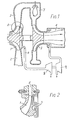
- a compressor 1 which through a compressor diffuser 2 supplies compressed air to a combustion chamber 7.
- the gases from the combustion chamber are passed to a turbine 3 having a stepped exhaust gas diffuser 4.
- the turbine 3 drives the compressor 1.
- the turbine 3 generates substantially more energy than required for driving the compressor 1 and also supplies energy for operating a further load, e.g. an electric power generator which is not shown.
- Compressed air leaking through a conventional labyrinth seal 5 of the compressor 1 is bled off through a conduit 6 which leads to an air turbine 8 operating a pump or compressor 9 for removing working medium by suction from the vortex flow in the stepped exhaust gas diffuser 4.
- an ejector operated by the leakage air to produce the suction required to remove working medium from the diffuser 4.
- the use of an ejector provides the best results when the air from the compressor 1 and the working medium from the diffuser 4 have approximately the same density.
- ejectors may still be preferable in connection with small machines, since they have various other advantages such as low costs.
- the bleedoff of air from the compressor 1 may also be combined with a cooling of hot parts l of the machinery, said air being used for cooling prior to utilizing the energy in the air in connection with a bleedoff from the exhaust gas diffuser.
- a cooling of hot parts l of the machinery said air being used for cooling prior to utilizing the energy in the air in connection with a bleedoff from the exhaust gas diffuser.
- Fig. 2 shows schematically on a larger scale the labyrinth seal through which the compressed air flows before it reaches the onduit 6. Leakage of higher that atmospheric pressure air through clearances between rotating and static parts of a turbo-machine is unavoidable. At the exit of a centrifugal compressor 0,5% to 2% of the air has normally to be bled from the engine cycle and this represents a performance penalty. For compressors with pressure ratios above 7:1 this air is too hot to be used as bearing seal air. The present invention uses this "lost" air to control the boundary layer in the turbine exhaust diffuser.
- air from the exit portion of a compressor 1 leaks through labyrinth seals generally indicated at 5.
- this normally wasted leaking air is bled off through the conduit 6 and fed to an ejector inlet line (not shown) or to the inlet of an air turbine as shown at 8 in Fig.l.
- the invention can use the compressor leakage air either as primary air in a jetpump or ejector or to drive a compressor 9 which thus pumps the subatmospheric air out from the exhaust gas diffuser 4.
- the predicted improvement in exhaust diffuser performance is large enough to provide a net improvement in power output and thermal efficiency in addition to make up for the lost air.
- the working medium is air and combustion gases respectively, since the invention is illustrated in connection with turbo-chargers and turboshaft engines. However, a corresponding effect may be obtained in connection with other fluids.
- the use of other working mediums, especially vapour and other gases, is therefore within the scope of the invention.
Landscapes
- Engineering & Computer Science (AREA)
- Mechanical Engineering (AREA)
- General Engineering & Computer Science (AREA)
- Life Sciences & Earth Sciences (AREA)
- Sustainable Development (AREA)
- Structures Of Non-Positive Displacement Pumps (AREA)
- Jet Pumps And Other Pumps (AREA)
Applications Claiming Priority (2)
| Application Number | Priority Date | Filing Date | Title |
|---|---|---|---|
| US309239 | 1981-10-06 | ||
| US06/309,239 US4459802A (en) | 1978-01-02 | 1981-10-06 | Bleedoff of gas diffusers in fluid flow machines |
Publications (3)
| Publication Number | Publication Date |
|---|---|
| EP0076668A2 true EP0076668A2 (de) | 1983-04-13 |
| EP0076668A3 EP0076668A3 (en) | 1983-10-05 |
| EP0076668B1 EP0076668B1 (de) | 1986-08-27 |
Family
ID=23197331
Family Applications (1)
| Application Number | Title | Priority Date | Filing Date |
|---|---|---|---|
| EP82305243A Expired EP0076668B1 (de) | 1981-10-06 | 1982-10-01 | Turbomaschinen mit einer Entlüftungsvorrichtung |
Country Status (3)
| Country | Link |
|---|---|
| EP (1) | EP0076668B1 (de) |
| JP (1) | JPS5879608A (de) |
| DE (2) | DE76668T1 (de) |
Cited By (9)
| Publication number | Priority date | Publication date | Assignee | Title |
|---|---|---|---|---|
| GB2242235A (en) * | 1990-03-06 | 1991-09-25 | Gen Electric | Aircraft engine bleed system |
| US5125597A (en) * | 1990-06-01 | 1992-06-30 | General Electric Company | Gas turbine engine powered aircraft environmental control system and boundary layer bleed with energy recovery system |
| US5137230A (en) * | 1991-06-04 | 1992-08-11 | General Electric Company | Aircraft gas turbine engine bleed air energy recovery apparatus |
| US5143329A (en) * | 1990-06-01 | 1992-09-01 | General Electric Company | Gas turbine engine powered aircraft environmental control system and boundary layer bleed |
| GB2285669A (en) * | 1994-01-13 | 1995-07-19 | Short Brothers Plc | Boundary layer control in aerodynamic structures |
| EP0961033A1 (de) * | 1998-05-25 | 1999-12-01 | Asea Brown Boveri Ag | Radialverdichter |
| US6540480B2 (en) | 2000-02-23 | 2003-04-01 | Holset Engineering Company, Ltd. | Compressor |
| EP1329595A1 (de) * | 2002-01-22 | 2003-07-23 | Snecma Moteurs | Diffusor für Luftfahrt- oder Industriegasturbinen |
| US8389886B2 (en) | 2005-09-26 | 2013-03-05 | Abb Technology Ag | High-voltage circuit breaker with improved circuit breaker rating |
Families Citing this family (3)
| Publication number | Priority date | Publication date | Assignee | Title |
|---|---|---|---|---|
| US8313286B2 (en) * | 2008-07-28 | 2012-11-20 | Siemens Energy, Inc. | Diffuser apparatus in a turbomachine |
| US8474266B2 (en) | 2009-07-24 | 2013-07-02 | General Electric Company | System and method for a gas turbine combustor having a bleed duct from a diffuser to a fuel nozzle |
| US20120186261A1 (en) * | 2011-01-20 | 2012-07-26 | General Electric Company | System and method for a gas turbine exhaust diffuser |
Family Cites Families (5)
| Publication number | Priority date | Publication date | Assignee | Title |
|---|---|---|---|---|
| FR935783A (fr) * | 1946-01-25 | 1948-06-30 | Goetaverken Ab | Perfectionnements aux compresseurs actionnés par des turbines |
| FR1199042A (fr) * | 1958-05-28 | 1959-12-10 | Bertin & Cie | Perfectionnements apportés à l'alimentation en énergie des appareils à circuits pneumatiques |
| US3109285A (en) * | 1959-08-03 | 1963-11-05 | Boeing Co | Accessory power system for aircraft |
| US3604206A (en) * | 1968-07-31 | 1971-09-14 | Gen Electric | Shaft-sealing system for nuclear turbines |
| US3856430A (en) * | 1973-07-27 | 1974-12-24 | Gen Motors Corp | Diffuser with boundary layer removal |
-
1982
- 1982-10-01 EP EP82305243A patent/EP0076668B1/de not_active Expired
- 1982-10-01 DE DE1982305243 patent/DE76668T1/de active Pending
- 1982-10-01 DE DE8282305243T patent/DE3272914D1/de not_active Expired
- 1982-10-05 JP JP17525782A patent/JPS5879608A/ja active Pending
Cited By (13)
| Publication number | Priority date | Publication date | Assignee | Title |
|---|---|---|---|---|
| GB2242235A (en) * | 1990-03-06 | 1991-09-25 | Gen Electric | Aircraft engine bleed system |
| US5125597A (en) * | 1990-06-01 | 1992-06-30 | General Electric Company | Gas turbine engine powered aircraft environmental control system and boundary layer bleed with energy recovery system |
| US5143329A (en) * | 1990-06-01 | 1992-09-01 | General Electric Company | Gas turbine engine powered aircraft environmental control system and boundary layer bleed |
| US5137230A (en) * | 1991-06-04 | 1992-08-11 | General Electric Company | Aircraft gas turbine engine bleed air energy recovery apparatus |
| GB2285669A (en) * | 1994-01-13 | 1995-07-19 | Short Brothers Plc | Boundary layer control in aerodynamic structures |
| GB2285669B (en) * | 1994-01-13 | 1998-06-10 | Short Brothers Plc | Boundary layer control in aerodynamic low drag structures |
| EP0961033A1 (de) * | 1998-05-25 | 1999-12-01 | Asea Brown Boveri Ag | Radialverdichter |
| US6190123B1 (en) | 1998-05-25 | 2001-02-20 | Asea Brown Boverti Ag | Centrifugal compressor |
| US6540480B2 (en) | 2000-02-23 | 2003-04-01 | Holset Engineering Company, Ltd. | Compressor |
| EP1329595A1 (de) * | 2002-01-22 | 2003-07-23 | Snecma Moteurs | Diffusor für Luftfahrt- oder Industriegasturbinen |
| FR2835019A1 (fr) * | 2002-01-22 | 2003-07-25 | Snecma Moteurs | Diffuseur pour moteur a turbine a gaz terrestre ou aeronautique |
| US6973771B2 (en) | 2002-01-22 | 2005-12-13 | Snecma Moteurs | Diffuser for terrestrial or aviation gas turbine |
| US8389886B2 (en) | 2005-09-26 | 2013-03-05 | Abb Technology Ag | High-voltage circuit breaker with improved circuit breaker rating |
Also Published As
| Publication number | Publication date |
|---|---|
| EP0076668B1 (de) | 1986-08-27 |
| DE76668T1 (de) | 1983-12-22 |
| JPS5879608A (ja) | 1983-05-13 |
| EP0076668A3 (en) | 1983-10-05 |
| DE3272914D1 (en) | 1986-10-02 |
Similar Documents
| Publication | Publication Date | Title |
|---|---|---|
| US4459802A (en) | Bleedoff of gas diffusers in fluid flow machines | |
| CN1280531C (zh) | 减少冷却空气流的压气机系统和方法 | |
| US5473899A (en) | Turbomachinery for Modified Ericsson engines and other power/refrigeration applications | |
| US3462071A (en) | Arrangements for radial flow compressors for supercharging internal combustion engines | |
| EP0298011B1 (de) | In einer Rotorkappe montiertes Schmier- und Kühlsystem | |
| US4711084A (en) | Ejector assisted compressor bleed | |
| CA1045040A (en) | Turbine vane cooling | |
| US8172512B2 (en) | Accessory gearbox system with compressor driven seal air supply | |
| EP0188910B1 (de) | Turbinenschaufelkühlung | |
| US8205426B2 (en) | Method and apparatus for operating gas turbine engines | |
| US6397604B2 (en) | Cooling supply system for stage 3 bucket of a gas turbine | |
| US2951340A (en) | Gas turbine with control mechanism for turbine cooling air | |
| EP0076668B1 (de) | Turbomaschinen mit einer Entlüftungsvorrichtung | |
| US7430865B2 (en) | Miniaturized waste heat engine | |
| CN101178014A (zh) | 双重级间冷却发动机 | |
| GB1113087A (en) | Gas turbine power plant | |
| US20150337760A1 (en) | Miniaturized waste heat engine | |
| JPH0343630A (ja) | 航空機エンジンを非航空用エンジンに転換する方法および非航空用エンジン | |
| US6089010A (en) | System for compensating for a pressure loss in the cooling-air ducting in a gas turbine plant | |
| GB2253442A (en) | Multi-stage seal for an axial flow turbine | |
| US20180135448A1 (en) | A gas turbine engine | |
| GB2110767A (en) | A shrouded rotor for a gas turbine engine | |
| EP0098363B1 (de) | Gasturbine mit Kontrolle der Schaufeltemperatur | |
| US1263056A (en) | Operation of centrifugal-compressor plants. | |
| GB2395753A (en) | Fuel compressor system for a gas turbine |
Legal Events
| Date | Code | Title | Description |
|---|---|---|---|
| PUAI | Public reference made under article 153(3) epc to a published international application that has entered the european phase |
Free format text: ORIGINAL CODE: 0009012 |
|
| AK | Designated contracting states |
Designated state(s): DE FR GB NL SE |
|
| PUAL | Search report despatched |
Free format text: ORIGINAL CODE: 0009013 |
|
| EL | Fr: translation of claims filed | ||
| TCNL | Nl: translation of patent claims filed | ||
| AK | Designated contracting states |
Designated state(s): DE FR GB NL SE |
|
| 17P | Request for examination filed |
Effective date: 19830919 |
|
| DET | De: translation of patent claims | ||
| GRAA | (expected) grant |
Free format text: ORIGINAL CODE: 0009210 |
|
| AK | Designated contracting states |
Kind code of ref document: B1 Designated state(s): DE FR GB NL SE |
|
| REF | Corresponds to: |
Ref document number: 3272914 Country of ref document: DE Date of ref document: 19861002 |
|
| PGFP | Annual fee paid to national office [announced via postgrant information from national office to epo] |
Ref country code: NL Payment date: 19861031 Year of fee payment: 5 |
|
| ET | Fr: translation filed | ||
| PLBE | No opposition filed within time limit |
Free format text: ORIGINAL CODE: 0009261 |
|
| STAA | Information on the status of an ep patent application or granted ep patent |
Free format text: STATUS: NO OPPOSITION FILED WITHIN TIME LIMIT |
|
| 26N | No opposition filed | ||
| PG25 | Lapsed in a contracting state [announced via postgrant information from national office to epo] |
Ref country code: SE Effective date: 19871002 |
|
| PG25 | Lapsed in a contracting state [announced via postgrant information from national office to epo] |
Ref country code: NL Effective date: 19880501 |
|
| GBPC | Gb: european patent ceased through non-payment of renewal fee | ||
| NLV4 | Nl: lapsed or anulled due to non-payment of the annual fee | ||
| PG25 | Lapsed in a contracting state [announced via postgrant information from national office to epo] |
Ref country code: FR Free format text: LAPSE BECAUSE OF NON-PAYMENT OF DUE FEES Effective date: 19880630 |
|
| PG25 | Lapsed in a contracting state [announced via postgrant information from national office to epo] |
Ref country code: DE Effective date: 19880701 |
|
| REG | Reference to a national code |
Ref country code: FR Ref legal event code: ST |
|
| PG25 | Lapsed in a contracting state [announced via postgrant information from national office to epo] |
Ref country code: GB Free format text: LAPSE BECAUSE OF NON-PAYMENT OF DUE FEES Effective date: 19881121 |
|
| EUG | Se: european patent has lapsed |
Ref document number: 82305243.6 Effective date: 19880712 |