EP0076768A1 - Vorrichtung zum Eintreiben und Herausziehen von Pfählen, Rohren, Spundwänden, Stangen, usw. - Google Patents
Vorrichtung zum Eintreiben und Herausziehen von Pfählen, Rohren, Spundwänden, Stangen, usw. Download PDFInfo
- Publication number
- EP0076768A1 EP0076768A1 EP82420120A EP82420120A EP0076768A1 EP 0076768 A1 EP0076768 A1 EP 0076768A1 EP 82420120 A EP82420120 A EP 82420120A EP 82420120 A EP82420120 A EP 82420120A EP 0076768 A1 EP0076768 A1 EP 0076768A1
- Authority
- EP
- European Patent Office
- Prior art keywords
- driving
- tearing
- anvil
- driven
- hammers
- Prior art date
- Legal status (The legal status is an assumption and is not a legal conclusion. Google has not performed a legal analysis and makes no representation as to the accuracy of the status listed.)
- Granted
Links
- 238000005553 drilling Methods 0.000 claims abstract description 8
- 239000012530 fluid Substances 0.000 claims abstract description 6
- 238000004804 winding Methods 0.000 claims description 13
- 230000005540 biological transmission Effects 0.000 claims description 5
- 239000000725 suspension Substances 0.000 claims description 4
- 239000000696 magnetic material Substances 0.000 claims description 3
- 230000035939 shock Effects 0.000 abstract description 10
- 238000009527 percussion Methods 0.000 abstract 2
- 239000006096 absorbing agent Substances 0.000 abstract 1
- 238000006073 displacement reaction Methods 0.000 description 3
- 210000005069 ears Anatomy 0.000 description 2
- 230000000694 effects Effects 0.000 description 2
- 230000010355 oscillation Effects 0.000 description 2
- 230000000149 penetrating effect Effects 0.000 description 2
- 238000011084 recovery Methods 0.000 description 2
- 235000002767 Daucus carota Nutrition 0.000 description 1
- 244000000626 Daucus carota Species 0.000 description 1
- 241001080024 Telles Species 0.000 description 1
- 230000003042 antagnostic effect Effects 0.000 description 1
- 230000000295 complement effect Effects 0.000 description 1
- 238000000605 extraction Methods 0.000 description 1
- 238000003754 machining Methods 0.000 description 1
- 230000035515 penetration Effects 0.000 description 1
- 230000001737 promoting effect Effects 0.000 description 1
- 230000003252 repetitive effect Effects 0.000 description 1
- 208000027765 speech disease Diseases 0.000 description 1
- 230000007704 transition Effects 0.000 description 1
Images


Classifications
-
- E—FIXED CONSTRUCTIONS
- E02—HYDRAULIC ENGINEERING; FOUNDATIONS; SOIL SHIFTING
- E02D—FOUNDATIONS; EXCAVATIONS; EMBANKMENTS; UNDERGROUND OR UNDERWATER STRUCTURES
- E02D11/00—Methods or apparatus specially adapted for both placing and removing sheet pile bulkheads, piles, or mould-pipes
-
- B—PERFORMING OPERATIONS; TRANSPORTING
- B25—HAND TOOLS; PORTABLE POWER-DRIVEN TOOLS; MANIPULATORS
- B25D—PERCUSSIVE TOOLS
- B25D11/00—Portable percussive tools with electromotor or other motor drive
- B25D11/06—Means for driving the impulse member
- B25D11/064—Means for driving the impulse member using an electromagnetic drive
-
- E—FIXED CONSTRUCTIONS
- E02—HYDRAULIC ENGINEERING; FOUNDATIONS; SOIL SHIFTING
- E02D—FOUNDATIONS; EXCAVATIONS; EMBANKMENTS; UNDERGROUND OR UNDERWATER STRUCTURES
- E02D7/00—Methods or apparatus for placing sheet pile bulkheads, piles, mouldpipes, or other moulds
- E02D7/02—Placing by driving
- E02D7/06—Power-driven drivers
Definitions
- the present invention relates to a device for driving and tearing off elements such as: piles, tubes, sheet piling, rods, etc., which are used in the fields of public works, quarries, mines and drilling industries.
- the effect of the shocks must be in the direction of the penetration movement, the energy of the shock transmitted to the element to be driven being divided into two components, one causing the vibration of the element, promoting sliding in the ground, the other component ensuring the displacement of the element.
- the direction of the shocks applied will be vertical and the direction of the shocks oriented from top to bottom.
- the present invention aims to eliminate all of these drawbacks by providing an apparatus using a new energy source in the field considered, this apparatus being of simple and robust structure, with a minimum of moving parts, having a non-functioning influenced by external temperature conditions, and bringing together in a compact unit all the means necessary for both driving and tearing, the passage from one to the other of these two operations being effected by a simple switching , without any overturning or other movement of the device.
- the invention relates to a driving and tearing device for piles, tubes, sheet piles, rods, etc., which essentially comprises two superimposed electromagnetic hammers, arranged along the same axis and acting in opposite directions, between which is mounted a common oscillating mobile mass, suspended elastically, the respective pole pieces of the two hammers constituting anvils, of which the lower one, struck by the mobile mass for driving, is provided at its outer end with means allowing the connection of the elements to be driven or to be torn off, and the upper one, struck by the moving mass for tearing, is connected to the lower one by a shaft or a tube made of non-magnetic material passing right through the moving mass by a hole drilled along the axis of this last.
- a driving system and a tearing system which operate on the basis of electrical energy and which use a common striking moving mass, the ends of which can penetrate respectively into the windings two electromagnetic hammers to form its mobile cores, this mobile mass being suspended for example between two opposing springs allowing it to oscillate on either side of a rest position.
- the two electromagnetic hammers of the device object of the invention are used alternately, one used for driving and the other for tearing, and never enter service simultaneously, these two hammers are advantageously connected to a common electrical supply and control system, by means of a switch making it possible to direct current pulses at will to the winding of one of the hammers for driving or to the winding of the other hammer for driving 'tearing of the element connected to the lower anvil. It is understood that, for tearing, the mobile mass attracted by the upper winding strikes the corresponding anvil, which transmits the energy received to the lower anvil via the shaft or the connecting tube, while for driving the moving mass, attracted by the lower winding, directly strikes the anvil to which the elements to be driven are connected.
- the connecting element between the two anvils which passes right through the moving mass, is a tube extended by axial bores provided respectively in the two anvils, to constitute a continuous axial passage.
- This last characteristic is compatible with the presence of rotational drive means but in this case, in order to allow the recovery of the cores or the arrival of the drilling fluid, it will preferably be chosen for the said rotational drive means the lateral arrangement defined above, so as to free the upper part of the apparatus.
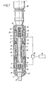
- the driving and tearing device represented in FIG. 1, comprises a central movable mass 1 which can strike, by each of its ends, either on a lower anvil 2 intended for driving, or on an upper anvil 3 intended for tearing.
- the two anvils 2 and 3 are interconnected by a shaft 4 made of non-magnetic material, passing right through the movable mass 1 through a hole 5 drilled along the axis 6 of the latter.
- the moving mass 1 is common to two electromagnetic hammers 7 and 8, arranged along the axis 6 and each produced according to French patent No. 2430827.
- the lower hammer 7 comprises a coil 9 surrounded by a shield 10; the lower neclume 2 serves as a fixed pole piece, through its cylindrical part 11 introduced inside the winding 9, while the lower end of the mass 1 serves as a mobile core for the hammer 7 also penetrating into its winding 9.
- the upper hammer 8 comprises a coil 12 surrounded by a shield 13; the upper anvil 3 serves as a fixed pole piece through its cylindrical part 14 introduced inside the coil 12, while the upper end of the mass 1 serves as a movable core for the hammer 8, also penetrating into its coil 12.
- the movable mass 1 has a flange 15, on either side of which bear, respectively, two helical springs 16 and 17 antagonistic.
- the lower spring 16 is compressed between the flange 15 and a ring 18 located above the shield 10 of the lower hammer 7, while the upper spring 17 is compressed between the flange 15 and a ring 19 placed below the shield 13 of the Tue upper level 8.
- the assembly of the two electromagnetic hammers 7 and 8 and their common mobile mass 1 is disposed under extreme housings 20 and central 21 assembled properly. To be used, this whole assembly is mounted on an external support, not shown, for example a slide with the necessary displacement means.
- the two electromagnetic hammers 7 and 8 are both connected to a common electrical supply and control system, symbolized by a block 22 and produced according to French patent No. 2,356,483 and its addition N D 2 425 302.
- a switching device 23 makes it possible to direct the current from the electrical discharge circuit to one or the other of the two windings 9 and 12.
- the operator places the switching device 23 in its position putting the babbling 9 of the lower electromagnetic hammer 7 into circuit.
- the lower end of the mobile mass 1 suspended by the springs 16 and 17 strikes the cylindrical part 11 of the lower anvil 2, the flange 24 of which presses against a stop 25.
- the lower anvil 2 transmits the kinetic energy received from the moving mass 1 to the element to be driven, fixed to the lower end of said anvil 2 by an assembly adapted to each application case.
- the operator places the switching device 23 in its other position switching on the winding 12 of the upper electromagnetic hammer 8.
- the upper end of the moving mass 1 strikes the cylindrical part 14 of the upper anvil 3, the flange 26 of which comes to rest on a corresponding stop 27.
- the upper anvil 3 transmits the kinetic energy received from the moving mass 1 to the lower anvil 2 , via the connecting shaft 4, the lower anvil 2 itself transmitting this energy to the element to be torn off.
- the length of the shaft 4 which connects the two anvils 2 and 3 together is such that, when one is in the driving position, the upper anvil 3 cannot receive the shocks in return due to the oscillation of the moving mass 1 caused by the lower hammer 7; conversely, in the tear-off position, the lower anvil 2 will not receive back impacts due to the oscillation of the moving mass 1 caused by the upper hammer 8.
- a drive in rotation of the element to be driven is obtained, in addition, by a rotation device disposed above the double electromagnetic hammer 7-8, along the axis. 6 of this double hammer.
- An electric gear motor 28, clamped on the upper cover 41 has its output shaft 29 linked in rotation with the upper anvil 3 by means of grooves allowing the axial movement of this anvil 3..
- the rotational movement is transmitted by the connecting shaft 4 to the lower anvil 2, which itself communicates it to the element to darken.
- FIG. 2 represents a second embodiment which does not differ from the first as regards the arrangement of the double electromagnetic hammer 7-8, but in which the driving in rotation of the element to be driven is obtained by a device placed laterally.
- a gear motor 30, of axis 31 parallel to the main axis 6 of the device, is clamped on a casing 32 secured to the lower part of the device.
- the output shaft 33 of the gear motor 30 carries a pinion 34, connected by an endless chain 35 to another pinion 36 machined with a housing in the form of "hexagon socket" along its axis.
- the pinion 36 is slidably mounted around the lower anvil 2, having a complementary external machining with hexagon 37, which allows the anvil 2 to rotate, therefore the element to be driven in rotation, without preventing the axial displacement of this anvil 2. All the transmission described above is housed inside the casing 32.
- the connecting shaft and the anvils can be drilled right through, the shaft in question in this case being replaced by a tube 38 and the anvils 2 and 3 having axial holes respectively 39 and 40, which extend the tube 38.
- the upper cover 41 an orifice 42 drilled along the axis 6, there is then a continuous axial passage, for the extraction and recovery of carrots at the upper part of the device, possibly for the circulation of fluids used in drilling operations.
- the driving and pulling device described above is applicable to various elements such as: piles, tubes, sheet piling, rods, etc.
- the outer end of the lower anvil 2 comprises, for the connection of these elements , means 42 adapted to each application case, for example a threaded head for screwable elements.
- means 42 adapted to each application case, for example a threaded head for screwable elements.
- the invention is more particularly applicable to the field of drilling.
- the driving and tearing device object of the invention can be, as illustrated in Figure 3, suspended from the cable 43 d 'a crane ; in this case it is advantageous to connect the cable 43 to the top of the body 44 of the device by a flexible element 45, such as a spring or block of rubber.
- a flexible element 45 such as a spring or block of rubber. The transition from driving to tearing is then done by moving the body 44 of the device relative to the anvils secured to the elements to be driven or torn off.
- This movement can be obtained by letting the body 44 of the device rest through the stop. 25 on the lower anvil 2 (see Figures 1 and 2) for driving, and pulling the body 44 upward to bring the upper anvil 3 into contact with the upper stop 27, for tearing, flexible hooking element 45 making it possible to absorb the pull-out jolts while avoiding transmitting them to the suspension cable 43.
- the upper anvil 3 has two lateral ears 46, situated outside the body 44 between the two lugs 47 for attaching the device to a cable or other suspension means.
- Two small electric jacks 48 have their bodies fixed on either side of the upper part of the body 44 of the device, while their rods 49 are connected respectively to the two ears 46, with the interposition of discs or elastic studs 50.
- This mounting has the advantage of not transmitting vibrations to the cable or other suspension means, the reversing pulse being taken up on the elements to be darkened.
Landscapes
- Engineering & Computer Science (AREA)
- Life Sciences & Earth Sciences (AREA)
- General Life Sciences & Earth Sciences (AREA)
- Mining & Mineral Resources (AREA)
- Paleontology (AREA)
- Civil Engineering (AREA)
- General Engineering & Computer Science (AREA)
- Structural Engineering (AREA)
- Physics & Mathematics (AREA)
- Electromagnetism (AREA)
- Mechanical Engineering (AREA)
- Placing Or Removing Of Piles Or Sheet Piles, Or Accessories Thereof (AREA)
- Earth Drilling (AREA)
- Perforating, Stamping-Out Or Severing By Means Other Than Cutting (AREA)
- Percussive Tools And Related Accessories (AREA)
- Refuge Islands, Traffic Blockers, Or Guard Fence (AREA)
- Portable Nailing Machines And Staplers (AREA)
Priority Applications (1)
| Application Number | Priority Date | Filing Date | Title |
|---|---|---|---|
| AT82420120T ATE13451T1 (de) | 1981-10-02 | 1982-08-24 | Vorrichtung zum eintreiben und herausziehen von pfaehlen, rohren, spundwaenden, stangen, usw. |
Applications Claiming Priority (2)
| Application Number | Priority Date | Filing Date | Title |
|---|---|---|---|
| FR8119118 | 1981-10-02 | ||
| FR8119118A FR2514049A1 (fr) | 1981-10-02 | 1981-10-02 | Dispositif de foncage et d'arrachement pour pieux, tubes, palplanches, tiges, etc. |
Publications (2)
| Publication Number | Publication Date |
|---|---|
| EP0076768A1 true EP0076768A1 (de) | 1983-04-13 |
| EP0076768B1 EP0076768B1 (de) | 1985-05-22 |
Family
ID=9262929
Family Applications (1)
| Application Number | Title | Priority Date | Filing Date |
|---|---|---|---|
| EP82420120A Expired EP0076768B1 (de) | 1981-10-02 | 1982-08-24 | Vorrichtung zum Eintreiben und Herausziehen von Pfählen, Rohren, Spundwänden, Stangen, usw. |
Country Status (7)
| Country | Link |
|---|---|
| US (1) | US4468594A (de) |
| EP (1) | EP0076768B1 (de) |
| JP (1) | JPS5869929A (de) |
| AT (1) | ATE13451T1 (de) |
| CA (1) | CA1204729A (de) |
| DE (1) | DE3263759D1 (de) |
| FR (1) | FR2514049A1 (de) |
Cited By (2)
| Publication number | Priority date | Publication date | Assignee | Title |
|---|---|---|---|---|
| EP0648582A1 (de) * | 1993-10-19 | 1995-04-19 | Yamada Juki Co., Ltd. | Rotierender Schlagapparat |
| CN111287183A (zh) * | 2020-03-27 | 2020-06-16 | 安徽一诺青春工业设计有限公司 | 一种道路建设的打桩装置 |
Families Citing this family (16)
| Publication number | Priority date | Publication date | Assignee | Title |
|---|---|---|---|---|
| US4799557A (en) * | 1985-04-29 | 1989-01-24 | Martelec - Societe Civile Particuliere | Electromagnetic pile driver |
| FR2581100B1 (fr) * | 1985-04-29 | 1987-10-09 | Martelec | Mouton de battage electro-magnetique |
| US5280673A (en) * | 1992-02-21 | 1994-01-25 | Electroimpact, Inc. | Electromagnetic bolt insertion system |
| US5241292A (en) * | 1992-05-28 | 1993-08-31 | Prime Mover, Inc. | Three position electrically operated actuator |
| DE4343589C1 (de) * | 1993-12-21 | 1995-04-27 | Klemm Guenter | Fluidbetätigter Schlaghammer |
| FR2765904B1 (fr) * | 1997-07-08 | 1999-10-08 | Jacques Demichelis | Marteau electromagnetique a masse ferromagnetique mobile |
| FR2802949B1 (fr) | 1999-12-22 | 2002-09-27 | Durmeyer Entrp Travaux Publics | Marteau electromagnetique a masse ferromagnetique mobile |
| DE10025371A1 (de) * | 2000-05-23 | 2001-11-29 | Hilti Ag | Handwerkzeuggerät mit elektromagnetischem Schlagwerk |
| FR2837412A1 (fr) * | 2002-03-22 | 2003-09-26 | Technifor | Dispositif de marquage en creux par percussions successives |
| US6695070B1 (en) * | 2002-08-05 | 2004-02-24 | Matsushita Electric Works, Ltd. | Magnetic impact device and method for magnetically generating impact motion |
| NZ528332A (en) * | 2003-09-22 | 2006-04-28 | Ramet Holdings Ltd | Impact driver for driving poles, piles or posts including linear induction motor |
| US10149711B2 (en) | 2012-03-30 | 2018-12-11 | Depuy Mitek, Llc | Surgical impact tool |
| KR20190046709A (ko) | 2016-08-31 | 2019-05-07 | 메디컬 엔터프라이시스 디스트리부션 엘엘씨 | 제어된, 반복 가능한 & 전환 가능한 충격력을 전달하는 론치된 매스를 구비하는 정형외과 충격 적용 장치 |
| US11083512B2 (en) | 2016-08-31 | 2021-08-10 | DePuy Synthes Products, Inc. | Orthopedic device delivering a controlled, repeatable impact |
| DE102018209564B4 (de) * | 2018-06-14 | 2021-05-20 | Krinner Innovation Gmbh | Eindrehvorrichtung mit schlagwirkung |
| GB2628084B (en) * | 2023-03-07 | 2025-06-11 | De Soutter Medical Ltd | Orthopaedic impactor |
Citations (3)
| Publication number | Priority date | Publication date | Assignee | Title |
|---|---|---|---|---|
| FR25277E (fr) * | 1919-07-10 | 1923-01-23 | Pieux à vis en béton armé pour fondations | |
| FR1107275A (fr) * | 1953-06-18 | 1955-12-29 | Metallwarenfabrik Markdorf Joh | Dispositif à commande électrique pour outils à mouvoir axialement |
| GB1125853A (en) * | 1967-01-16 | 1968-09-05 | Marutai Doboku Company Ltd | A pile driving apparatus including earth boring equipment |
Family Cites Families (6)
| Publication number | Priority date | Publication date | Assignee | Title |
|---|---|---|---|---|
| US1753454A (en) * | 1925-03-30 | 1930-04-08 | Central Electric Tool Company | Electric percussive tool |
| US2241364A (en) * | 1938-01-22 | 1941-05-06 | Hulbert Clinton Horace | Electromagnetic hammer |
| GB821164A (de) * | 1956-09-10 | |||
| FR2085507A1 (de) * | 1970-04-28 | 1971-12-24 | Drye Lucien | |
| FR2356483A1 (fr) * | 1976-06-28 | 1978-01-27 | Jacquemet Georges | Appareil de percussion electro-magnetique |
| JPS5645385A (en) * | 1979-09-18 | 1981-04-25 | Hideaki Kishida | Electromagnetic hammer |
-
1981
- 1981-10-02 FR FR8119118A patent/FR2514049A1/fr active Granted
-
1982
- 1982-08-24 EP EP82420120A patent/EP0076768B1/de not_active Expired
- 1982-08-24 DE DE8282420120T patent/DE3263759D1/de not_active Expired
- 1982-08-24 AT AT82420120T patent/ATE13451T1/de active
- 1982-09-07 CA CA000410875A patent/CA1204729A/fr not_active Expired
- 1982-09-24 US US06/423,082 patent/US4468594A/en not_active Expired - Fee Related
- 1982-10-01 JP JP57171069A patent/JPS5869929A/ja active Granted
Patent Citations (3)
| Publication number | Priority date | Publication date | Assignee | Title |
|---|---|---|---|---|
| FR25277E (fr) * | 1919-07-10 | 1923-01-23 | Pieux à vis en béton armé pour fondations | |
| FR1107275A (fr) * | 1953-06-18 | 1955-12-29 | Metallwarenfabrik Markdorf Joh | Dispositif à commande électrique pour outils à mouvoir axialement |
| GB1125853A (en) * | 1967-01-16 | 1968-09-05 | Marutai Doboku Company Ltd | A pile driving apparatus including earth boring equipment |
Cited By (3)
| Publication number | Priority date | Publication date | Assignee | Title |
|---|---|---|---|---|
| EP0648582A1 (de) * | 1993-10-19 | 1995-04-19 | Yamada Juki Co., Ltd. | Rotierender Schlagapparat |
| US5488997A (en) * | 1993-10-19 | 1996-02-06 | Yamada Juki Co., Ltd. | Rotary impacting apparatus |
| CN111287183A (zh) * | 2020-03-27 | 2020-06-16 | 安徽一诺青春工业设计有限公司 | 一种道路建设的打桩装置 |
Also Published As
| Publication number | Publication date |
|---|---|
| CA1204729A (fr) | 1986-05-20 |
| US4468594A (en) | 1984-08-28 |
| ATE13451T1 (de) | 1985-06-15 |
| JPH0354211B2 (de) | 1991-08-19 |
| JPS5869929A (ja) | 1983-04-26 |
| FR2514049B1 (de) | 1984-01-13 |
| EP0076768B1 (de) | 1985-05-22 |
| FR2514049A1 (fr) | 1983-04-08 |
| DE3263759D1 (en) | 1985-06-27 |
Similar Documents
| Publication | Publication Date | Title |
|---|---|---|
| EP0076768B1 (de) | Vorrichtung zum Eintreiben und Herausziehen von Pfählen, Rohren, Spundwänden, Stangen, usw. | |
| CA1310738C (fr) | Dispositif anti-rebond pour eviter les chocs multiples d'une masse mobile apres un premier choc contre un autre element | |
| EP0252863A1 (de) | Verfahren und Rammvorrichtung zum Eintreiben von Geräten in den Erdboden | |
| CA1305781C (fr) | Dispositif perfectionne pour engendrer des ondes acoustiques par percussion d'une masse chutant sur un element-cible couple avec les parois d'un puits | |
| EP0015857A1 (de) | Vorrichtung zum motorisierten Öffnen und Verschliessen eines Portals | |
| CA1221158A (fr) | Dispositif pour engendrer des impulsions sismiques a l'interieur d'un forage, par chute d'une masse sur un element-cible ancre | |
| CA2015054A1 (fr) | Dispositif anti-rebond pour une masse venant frapper un element-cible | |
| FR2506030A1 (fr) | Dispositif mixte d'emission d'ondes longitudinales ou transversales | |
| FR2597214A1 (fr) | Dispositif pour engendrer des ondes acoustiques par percussion d'une masse chutant sur un element cible ancre dans un puits | |
| EP3168396A1 (de) | Vorrichtung zum verriegeln für schiebetor, und entsprechendes schiebetor | |
| EP0168306B1 (de) | Bistabile Umsetzvorrichtung, insbesondere für eine Sauerstoffleitung an einem Flugzeug und das Verfahren dafür | |
| US2927773A (en) | Impact driver for well points and the like | |
| KR102289052B1 (ko) | 착용 가능한 케이블 피복 절단기가 구비된 스마트 스틱 및 이를 이용한 활선 작업 공법 | |
| CA2415359A1 (fr) | Appareil hydraulique a percussions | |
| EP1180576A1 (de) | Steuervorrichtung zur Betätigung eines Vorhangs | |
| FR2645138A1 (fr) | Engin de levage compact | |
| FR2482728A1 (fr) | Sonde de controle d'une plaque tubulaire | |
| FR2698944A1 (fr) | Motoréducteur. | |
| EP0210092B1 (de) | Schrittweise arbeitende Antriebsvorrichtung | |
| SU1216336A1 (ru) | Ударный механизм электродинамического действи | |
| BE1010674A3 (fr) | Machine pour creer un mouvement dans un liquide, en particulier des vagues a la surface de celui-ci. | |
| EP3023562A1 (de) | Türbewegungsvorrichtung mit elektrischer blockierung | |
| EP0188970A1 (de) | Betätigungsvorrichtung, anwendbar in einer Flüssigkeit unter Hochdruck | |
| SU1231216A1 (ru) | Устройство дл прижима приборов в скважине | |
| FR2830611A1 (fr) | Dispositif pour le deplacement d'une cible pour la pratique du tir |
Legal Events
| Date | Code | Title | Description |
|---|---|---|---|
| PUAI | Public reference made under article 153(3) epc to a published international application that has entered the european phase |
Free format text: ORIGINAL CODE: 0009012 |
|
| AK | Designated contracting states |
Designated state(s): AT BE CH DE GB IT LI LU NL SE |
|
| 17P | Request for examination filed |
Effective date: 19830921 |
|
| ITF | It: translation for a ep patent filed | ||
| GRAA | (expected) grant |
Free format text: ORIGINAL CODE: 0009210 |
|
| AK | Designated contracting states |
Designated state(s): AT BE CH DE GB IT LI LU NL SE |
|
| PG25 | Lapsed in a contracting state [announced via postgrant information from national office to epo] |
Ref country code: NL Effective date: 19850522 Ref country code: AT Effective date: 19850522 |
|
| REF | Corresponds to: |
Ref document number: 13451 Country of ref document: AT Date of ref document: 19850615 Kind code of ref document: T |
|
| REF | Corresponds to: |
Ref document number: 3263759 Country of ref document: DE Date of ref document: 19850627 |
|
| PG25 | Lapsed in a contracting state [announced via postgrant information from national office to epo] |
Ref country code: LU Free format text: LAPSE BECAUSE OF NON-PAYMENT OF DUE FEES Effective date: 19850831 Ref country code: LI Effective date: 19850831 Ref country code: CH Effective date: 19850831 |
|
| NLV1 | Nl: lapsed or annulled due to failure to fulfill the requirements of art. 29p and 29m of the patents act | ||
| PLBE | No opposition filed within time limit |
Free format text: ORIGINAL CODE: 0009261 |
|
| STAA | Information on the status of an ep patent application or granted ep patent |
Free format text: STATUS: NO OPPOSITION FILED WITHIN TIME LIMIT |
|
| REG | Reference to a national code |
Ref country code: CH Ref legal event code: PL |
|
| 26N | No opposition filed | ||
| BERE | Be: lapsed |
Owner name: MARTELEC Effective date: 19860831 |
|
| PG25 | Lapsed in a contracting state [announced via postgrant information from national office to epo] |
Ref country code: BE Effective date: 19890831 |
|
| PGFP | Annual fee paid to national office [announced via postgrant information from national office to epo] |
Ref country code: SE Payment date: 19910731 Year of fee payment: 10 |
|
| ITTA | It: last paid annual fee | ||
| PGFP | Annual fee paid to national office [announced via postgrant information from national office to epo] |
Ref country code: GB Payment date: 19920804 Year of fee payment: 11 |
|
| PGFP | Annual fee paid to national office [announced via postgrant information from national office to epo] |
Ref country code: DE Payment date: 19920805 Year of fee payment: 11 |
|
| PG25 | Lapsed in a contracting state [announced via postgrant information from national office to epo] |
Ref country code: SE Effective date: 19920825 |
|
| PG25 | Lapsed in a contracting state [announced via postgrant information from national office to epo] |
Ref country code: GB Effective date: 19930824 |
|
| GBPC | Gb: european patent ceased through non-payment of renewal fee |
Effective date: 19930824 |
|
| PG25 | Lapsed in a contracting state [announced via postgrant information from national office to epo] |
Ref country code: DE Effective date: 19940503 |
|
| EUG | Se: european patent has lapsed |
Ref document number: 82420120.6 Effective date: 19930307 |