EP0076857B1 - Spectacle frame for multi-focus spectacles - Google Patents
Spectacle frame for multi-focus spectacles Download PDFInfo
- Publication number
- EP0076857B1 EP0076857B1 EP82900315A EP82900315A EP0076857B1 EP 0076857 B1 EP0076857 B1 EP 0076857B1 EP 82900315 A EP82900315 A EP 82900315A EP 82900315 A EP82900315 A EP 82900315A EP 0076857 B1 EP0076857 B1 EP 0076857B1
- Authority
- EP
- European Patent Office
- Prior art keywords
- holder
- nosepad
- nosepads
- swivel
- lens
- Prior art date
- Legal status (The legal status is an assumption and is not a legal conclusion. Google has not performed a legal analysis and makes no representation as to the accuracy of the status listed.)
- Expired
Links
- 230000007246 mechanism Effects 0.000 claims description 22
- 230000008859 change Effects 0.000 claims description 5
- 210000001331 nose Anatomy 0.000 description 16
- 208000003464 asthenopia Diseases 0.000 description 3
- 238000012986 modification Methods 0.000 description 3
- 230000004048 modification Effects 0.000 description 3
- 230000002301 combined effect Effects 0.000 description 2
- 238000006073 displacement reaction Methods 0.000 description 2
- 230000000694 effects Effects 0.000 description 2
- 238000005219 brazing Methods 0.000 description 1
- 238000010276 construction Methods 0.000 description 1
- 210000005069 ears Anatomy 0.000 description 1
- 210000004709 eyebrow Anatomy 0.000 description 1
- 230000001815 facial effect Effects 0.000 description 1
- 238000010348 incorporation Methods 0.000 description 1
- 238000003780 insertion Methods 0.000 description 1
- 230000037431 insertion Effects 0.000 description 1
- 230000009467 reduction Effects 0.000 description 1
- 230000001105 regulatory effect Effects 0.000 description 1
- 230000000717 retained effect Effects 0.000 description 1
- 230000007480 spreading Effects 0.000 description 1
- 229920003002 synthetic resin Polymers 0.000 description 1
- 239000000057 synthetic resin Substances 0.000 description 1
- 230000000007 visual effect Effects 0.000 description 1
Images




Classifications
-
- G—PHYSICS
- G02—OPTICS
- G02C—SPECTACLES; SUNGLASSES OR GOGGLES INSOFAR AS THEY HAVE THE SAME FEATURES AS SPECTACLES; CONTACT LENSES
- G02C5/00—Constructions of non-optical parts
-
- G—PHYSICS
- G02—OPTICS
- G02C—SPECTACLES; SUNGLASSES OR GOGGLES INSOFAR AS THEY HAVE THE SAME FEATURES AS SPECTACLES; CONTACT LENSES
- G02C7/00—Optical parts
- G02C7/02—Lenses; Lens systems ; Methods of designing lenses
- G02C7/06—Lenses; Lens systems ; Methods of designing lenses bifocal; multifocal ; progressive
-
- G—PHYSICS
- G02—OPTICS
- G02C—SPECTACLES; SUNGLASSES OR GOGGLES INSOFAR AS THEY HAVE THE SAME FEATURES AS SPECTACLES; CONTACT LENSES
- G02C5/00—Constructions of non-optical parts
- G02C5/12—Nose pads; Nose-engaging surfaces of bridges or rims
- G02C5/122—Nose pads; Nose-engaging surfaces of bridges or rims with adjustable means
- G02C5/124—Nose pads; Nose-engaging surfaces of bridges or rims with adjustable means for vertically varying the position of the lenses
-
- G—PHYSICS
- G02—OPTICS
- G02C—SPECTACLES; SUNGLASSES OR GOGGLES INSOFAR AS THEY HAVE THE SAME FEATURES AS SPECTACLES; CONTACT LENSES
- G02C5/00—Constructions of non-optical parts
- G02C5/22—Hinges
- G02C5/2263—Composite hinges, e.g. for varying the inclination of the lenses
Definitions
- the present invention relates to a frame for multifocal spectacles of the type in which the multifocal lenses can, by a simple operation, be both moved vertically and also tilted to change the angle of inclination relative to the normal line of vision (referred to as the horizontal line of vision when looking into the distance) so that the spectacles can always be worn with comfort whichever segment of the multifocal lens combination is used.
- FIG. 1 Various spectacles with bifocal lenses have been developed in which moving the nosepad pair up or down moves the spectacle frame in the vertical direction to permit proper use of the distance and close-up lens segments.
- Examples of spectacle frames with movable nosepads can be found in JP-A-53986, JP-U-53-158249, JP-U-50-138947, JP-U-56-5116 and US-A-2,321,083.
- these spectacles not only possess a complex mechanism but are also troublesome to manipulate.
- the lenses are ordinarily set at an angle that favors the use of the distance lens segments, and the angle of inclination does not change. When the close-up lens segments are used, therefore, these lens segments are not perpendicular to the line of vision.
- An object of the present invention is to provide a frame for multifocal spectacles capable not only of vertical movement relative to the normal line of vision but also of angular displacement in relation to the wearer's face by a simple operation, so that an optically ideal condition can be kept whichever pair of lens segments is used.
- US-A-3,907,410 there is described a frame for normal spectacles in which the side pieces have a hinge allowing the angle between the lenses and the side pieces to be pre-set to a desired angle.
- a frame for multifocal spectacles comprising a pair of lens rims to mount leftside and rightside multifocal lenses therein, a bridge for connecting between said lens rims, a nosepad for supporting the inner side of each of said lens rims against the sides of the nose, and a side piece attached to the outer side of each said lens rim, the nosepad being attached to the inner side of each of said lens rims through a level adjusting mechanism for moving the nosepad vertically to change the relative height of said lens rims with respect to the normal line of vision, characterized in that a hinge mechanism having two stops is provided between said side piece and said lens rim so that said side piece can be tilted relative to said rim through a prescribed angle so as to compensate for the angular position of the lens rims and nosepads attached thereto when the lens rims are elevated or lowered.
- the lens surfaces namely the lens rims supporting the lenses
- the hinge mechanisms which tilt the side pieces downwardly, so that the lenses take on the optimum angle with respect to the line of vision for close-up work (tilted slightly forward with respect to the normal line of vision).
- the close-up lenses are aligned with the height of the line of vision for close-up work by the nosepad level adjusting mechanism which changes the relative height of the lens rims with respect to the normal line of vision.
- Fig. 1 is a perspective view of a first embodiment of the bifocal spectacles of the present invention.
- the character A generally designates the main body of the spectacle frame.
- the main body A comprises a pair of leftside and rightside lenses 1, 1, a pair of lens rims 2, 2 forthe lenses 1, ,1, and a bridge 3 linking the paired rims 2, 2 at the portions slightly above center.
- Each of the lenses 1, 1 is a bifocal lens in which close-up lens segments 5, 5 are formed integral with the distance lens segments at the lower part thereof.
- FIG. 2 is an exploded, perspective view showing a mounting mechanism.
- the front end of the support 10 is rigidly attached to the outer side of each rim 2.
- the rear edge of the support 10 is cut in a curve, and a hole 11 is drilled near the curved edge.
- a holder 13 of generally U-shaped cross-section and which is provided with two holes 12, 12 is attached to the inner surface of the support 10 by braizing with the holes 12, 12 of the holder 13 aligned with the hole 11 in the support 10.
- a separate link 14 is provided.
- the forward end of the link 14 is shaped in a ⁇ -configuration to form an upper abutting face 15 and a lower abutting face 16 and is formed with a hole 17 near the front edge.
- the rear end of the link is provided with two vertically spaced rings 18, 18 one above the other.,
- the inner surface of the lower ring 18 has female threads.
- the link 14 is fit into the holder 13, the hole 17 of the link 14 is aligned with the holes 12, 12 in the holder 13, a nut 19 having female threads on its inner surface is inserted in the hole 12 of the holder 13, and a male screw 20 is inserted from the hole 11 of the support 10 to be screwed into and fastened by the nut 19.
- a separate swiveling joint 21 is provided.
- the forward end of the swiveling joint 21 is provided with a ring 22.
- the swiveling joint may be affixed to the side piece 9 by brazing.
- the ring 22 of the swiveling joint 21 is interposed between the rings 18, 18 of the link 14, after which a screw 23 is passed through the upper ring 18 of the link 14 and the ring 22 of the swiveling joint 21 and then screwed into and fastened by the lower ring 18. This completes assemblage, which state is shown in Fig. 3.
- the forward end of the side piece 9 is formed into an arcuate concave to match the arcuate shape of the rear end of the support 10, so that, when the side piece 9 is assembled, the rear end of the support 10 and the front end of the side piece 9 will match each other.
- the side piece 9 is rotated and folded inwardly about the fulcrum formed by tightened screw 23 between the rings 18, 18 of the link 14 and the ring 22 of the swiveling joint 21. Also, it is so designed that, when the side piece 9 is rotated outwardly, the front end of the side piece 9 abuts against the rear end of the support 10. Further, the side piece 9 can be rotated in a vertically abut the nut 19 and the male screw 20 between the holder 13 and the link 14. As can best be seen in Fig. 4, the upper abutting edge 15 of the link abuts against the holder 13 when the side piece 9 is rotated upwardly.
- the lower abutting edge 16 of the link 14 abuts against the holder 13 when the side piece 9 is rotated downwardly.
- a suitable frictional force is necessary. This frictional force can be obtained from the force used to tighten the screws 20 and 23. The more screw 20 or 23 is tightened, the more the U-shaped portion of the holder 13 will be pressed together, or the more the space between the rings 18, 18 of the link 14 will be narrowed, thereby increasing the frictional force.
- the frictional force can be regulated by adjusting the extent to which the screws are tightened.
- a pair of support rings 24, 24 are securely attached to the inner sides of the rims 2, 2 slightly below the bridge 3.
- the straight portions 25, 25 are inserted into the support rings 24 which are secured to the respective lens rims 2, 2.
- the actuating portions 26 is pinched and the slide frame 27 moved up and down, the straight portions 25, 25 are guided by the support rings 24, 24.
- the lower ends of the straight portions 25, 25 are respectively bent outward to form adjusting portions 28, 28.
- Nosepads 7, 7 are respectively mounted on the lowermost ends of the adjusting portions 28, 28. These adjusting portions 28, 28 are provided to permit the nose- pads 7, 7 to adjust their position to accommodate noses of various sizes and shapes. Therefore, such adjusting portions may be shaped otherwise, for example, S-, V-, U-shape. It should be noted that each of the straight portions 25, 25 is warped outwardly slightly, though this is not clearly seen from the drawings. When the slide frame 27 is moved up and down, forcing its straight portions 25, 25 to pass through the support rings 24, 24 a certain amount of resistance presents itself. Because of this, the slide frame, after being slid, is capable of staying in the upper or lower position with good stability. The same effect may also be attained, for example, by attaching to the inner wall of each support ring, a lining of synthetic resin having an inner diameter which is approximately equal to the diameter of the straight portions 25, 25 of the slide frame. This arrangement offers the required frictional force.
- each of the side pieces 9, 9 is aligned with the support, or not bent, as shown in Fig. 5.
- the slide frame 27 is raised, so the nosepads 7, 7 hold the spectacle frame at an upper position. This is done by pinching the actuating portion 26 and the bridge 3.
- the spectacle frame main body A is supported in a lowered condition, that is, with the optic axes of the distance lens segments 4, 4 aligned with the normal line of vision.
- the object When the close-up lens segments pair 5, 5 is used, the object generally is near at hand; hence the line of vision is inclined downward from the normal line of vision. Accordingly, the slide frame 27 is pushed downward to move the nosepads 7, 7 to a lower position. This is achieved by spreading apart the actuating portion 26 of the slide frame 27 and the bridge 3 to wider the spacing between them.
- the spectacles are worn with the main body A tilted forward. Since the nosepads 7, 7 abutting against both sides of the nose are situated downwardly and the side pieces 9, 9 are bent with respect to the supports 10, the main body A is supported at a high part of the nose while tilted slightly forward. In addition, the close-up lens segment pair 5, 5 is brought somewhat closer to the eyes.
- the tilt in the main body A in relation to the side pieces 9, 9, in addition to inclining the main body A serves also to decrease the distance between wearer's ears and spectacle nosepads 7, 7, causing upward movement of the frame main body A itself.
- the combined effect of the angular displacement of the side pieces 9, 9 relative to the main frame body A with the lower support of the nosepads 7, 7 enables the main frame body A to be supported in raised attitude.
- the amount by which the main body A is raised can be increased even when the degree of tilt in the side pieces 9, 9 is small.
- a small shaped area is shown, indicated at "a” in Fig. 5 and at “b” in Fig. 6, to represent the area of the nosepad that rests on the wearer's nose. It is so designed that the spacing between the nose- pads 7, 7 hardly changes when the main body A is supported at the upper position "a" and at the lower position "b". Because of this, the nosepads 7, 7 are located substantially at the same point on the nose.
- the nosepads 7, 7 of the first embodiment are moved vertically while being slid.
- the nosepads 7, 7 so designed are moved vertically while being swiveled up and down.
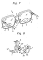
- holders 6, 6 in the second embodiment are plate shaped and have a curved forward end.
- the nosepads 7, 7 are attached to the holders 6 in such a manner that the nosepads can be rotated up and down.
- Fig. 8 presents a fragmentary sectional, exploded perspective view of the combination of the nosepad 7 and the holder 6.
- the holder 6 is formed at its forward end with a semicircle shaped slot, and with a slot, also of semicircle configuration but of smaller radius, cut in the holder opposite to the other semicircle shaped slot, so that the holder has two stepped portions 29 and 30 between the two slots.
- a hole 31 is bored laterally through the holder 6 to receive a pin therethrough.
- On the backside of the nosepad 7 is mounted a pad arm 32 of generally L-shape.
- the pad arm 32 is provided at its other end with a swivel 33.
- the swivel 33 is shaped like a circle with a sector shape integrally joined to its periphery, and is sized to be closely encased in the slots of the holder 6.
- the swivel therefore, also has two stepped portions 34 and 35 on the front and back sides of its sector portion, and is formed with a bore 36 in the center to receive a pin therethrough.
- the pin 37 is inserted and tightened by screwing to attach the nosepad 7 to the holder 6 via the pad arm 32 in such a manner that the nosepad can be swivelled.
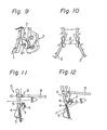
- Fig. 9 when the nosepad 7 is rotated downward, the stepped portion 35 of the swivel 33 abuts against the stepped portion 30 in the holder 6.
- the stepped portion 34 of the swivel 33 strikes the stepped portion 29 in the holder 6. As shown in Fig.
- the arrangement is such that the dimension of the spacing (1) between the nose- pads 7, 7 when they are rotated to the upper position is almost the same as the spacing (I') defined by the nosepads 7, 7 when swivelled to the lower point.
- the second embodiment of this invention in the manner shown in Figs. 11 and 12. First, when the pair of distance lens segments 4,4 is used, the side pieces 9, 9 are aligned with their respective support 10, as shown in Fig. 11, with the nosepads 7, 7 swivelled to the upper position. At this time the stepped portions 34, 34 of the swivel 33, 33 are abutted against and stably supported by the stepped portions 29, 29 in the holders 6, 6. In this position, the main frame body A is held at a low position on the wearer's nose.
- the nosepads 7, 7 must be rotated downward. This is achieved by manually pressing lightly the upper ends of the nosepads 7, against the facial reversed sloping area B, B adjacent to the eyebrows on the both sides of the nose, with the main frame body A lifted slightly off the face. This will result in the nosepads 7, 7 swivelling away from the rims 2, 2. (The simple operation of lifting the frame main body A causes swivelling of the nosepads 7, 7 as they abut against the reversed sloping areas B, B, so that the operation can be carried out spontaneously.)
- the distance between ear and nosepad 7 is reduced by the bend in the side piece 9.
- the combined effect of this reduction in distance with the lowered position of the nose- pads 7, 7 supports the main frame body A at the higher position. Further, the main frame body A is supported while tilted so that the close-up lenses 5, 5 are raised slightly and tilted slightly. This brings the lens 5, 5 close to the center of the line of vision and close to the eyes.
- the side pieces 9, 9 are aligned with the respective supports 10, 10, and the nosepads 7, 7 are rotated upward closer to the rims. This is accomplished by straightening the side pieces then by pushing down on the main frame body A in such a manner that the nosepads 7, 7, while being pressed against the nose, will rotate downward.
- the spectacles need not be removed.
- the space between the nosepads 7, 7 when they are rotated upward is almost the same as when they are rotated downward.
- the spacing can be altered by an optician to fit noses of various sizes and shapes. This may be done by changing the bend angle in the pad arm 32 of the nosepad 7, thereby to regulate the vertical distance travelled by the main frame body A.
- the pad arm may incorporate an adjusting element, between the swivel 33 and the nosepad 7, similar to the adjusting portion 28 of the first embodiment.
- a pad arm 32 is provided secured to the lens rim 2.
- the configuration of the pad arm may be similar to that of the adjusting portion 28 of the first embodiment.
- a ring holder 38 is affixed to the forward end of the pad arm, and is provided in its leading edge with a circular slot.
- a hole 31 to receive a pin 37 is bored in the side of the ring support 38, which is provided at its circumference with a protrusion 39.
- the nosepad 7 is provided at its backside with a swivel 33.
- a hole 36 is bored in the swivel 33.
- a projection 40 is formed just above the swivel 33 on the nosepad 7.
- the nosepad 7 used in the third embodiment is of generally V-cross sectional configuration, as depicted in and has an upper abutting surface 41 situated at the upper part, and a lower abutting surface 42 situated at the lower part.
- the parts shown in Fig. 13 are assembled into the form shown in Fig. 15. When the nosepad 7 is rotated upward, it will be stopped and stably engaged in position at a point where the projection 40 abuts lightly against the protrusion 39.
- Such stopping means for a case where the nosepads are rotated downwardly are omitted.
- the swivel 33 of the nosepad 7 is attached at a slightly upper position, the nosepad can be stably retained when the upper abutting surface 41 is used.
- the stopping means are provided solely on the upper portion.
- the same effect can be obtained without any stopping means as by suitable friction exerted by means of pin 37 located between the curved recess found in the ring holder 38 and the swivel 33 of the nosepad 7.
- the incorporation of such a stopping means depends altogether on the location of the swivel 33 on the nosepad 7 or manner of attachment. Other arrangements can be employed as the stopping means.
- the nosepad 7 is formed to have an L-shaped cross-section comprising an upper abutting surface 41 and a lower abutting surface 42.
- the object of such a bent contact surface is to hold the main frame body A in position on the sides of the nose in its upper and lower positions.
- Another object is to compensate for the change of angle that the nosepad front surface makes with the wearer's nose surface as the frame main body A is shifted.
- the upper abutting surface 41 has a larger surface area than the lower abutting surface 42, as can best be seen in Fig. 14.
- the lower abutting surface 42 may be made larger in surface area than the upper one 41, as shown in Fig. 17(A). Alternatively, they may have an equal surface area as shown in Fig. 17(B).
- Trifocal spectacles may employ nosepads of having three abutting surfaces, as shown in Fig. 17(C).
- Fig. 17(D) presents a view of the nosepad of a largely semi-spherically shaped front face for use with spectacles with lenses having more than three different foci. Throughout the views in Figs. 14 to 17, only the leftside nosepad, as viewed from the wearer, has been depicted for clarity of illustration. The rightside nosepad is symmetrically opposite in configuration to the leftside one.
- the mechanism is such that the side pieces 9, 9 can be folded inward or rotated downward. Only one joint can be seen from the side, giving a sense of neatness.
- the mechanism may have a structure as depicted in Figs. 18 and 19.
- the support 10 that is affixed to the rim 2 is formed at its rear edge with a longitudinal slot that is cut parallel with the side-piece surface to have a stepped recess portion 43.
- a separate link 44 also has at its forward end a stepped portion 45 for insertion into the stepped recess portion 43 and is connected to the support by means of a screw 46, about which the link 44 is made rotatable.
- the side piece 9 may be joined to the link 44 in a conventional manner, so that the side piece can be swung freely either inward with respect to the support 10 or outward to stably stay in position. Downward rotation of the side piece 9 is limited at a point where the stepped portion 45a of the link 44 contacts the stepped recess portion 43 in the slot of the support 10. When the side piece 9 is aligned with the support by rotating it upwardly, the former is prevented from further rotation upward by its upper forward edge 45b abutting against the upper edge of the support 10.
- Multifocal spectacles constructed in accordance with the present invention have their side pieces 9, 9, secured to the outer sides of the rims 2, 2, made rotatable horizontally and vertically through a hinge mechanism. Therefore, it is possible to alter the level of the frame relative to the eyes, simply by tilting the side pieces 9, 9 downward through a corresponding angle and, if necessary, by properly positioning the movable nosepads, so that the required segment pair of the multifocal lense combination can optionally be elevated in front of the eyes. Additionally, in order to obtain the optimum angle of inclination in the plane of the lenses for accurate focussing of the image, the angle that the side pieces 9, 9 take with their respective supports 10, 10 can readily be adjusted.
Landscapes
- Physics & Mathematics (AREA)
- Health & Medical Sciences (AREA)
- Ophthalmology & Optometry (AREA)
- General Physics & Mathematics (AREA)
- Optics & Photonics (AREA)
- General Health & Medical Sciences (AREA)
- Eyeglasses (AREA)
Priority Applications (1)
| Application Number | Priority Date | Filing Date | Title |
|---|---|---|---|
| AT82900315T ATE16425T1 (de) | 1981-04-17 | 1982-01-26 | Brillengestell fuer multifokales brillenglas. |
Applications Claiming Priority (4)
| Application Number | Priority Date | Filing Date | Title |
|---|---|---|---|
| JP59000/81 | 1981-04-17 | ||
| JP5900081A JPS57173813A (en) | 1981-04-17 | 1981-04-17 | Spectacle frame for multifocus |
| JP12480381A JPS5827122A (ja) | 1981-08-11 | 1981-08-11 | 多焦点用眼鏡枠 |
| JP124803/81 | 1981-08-11 |
Publications (3)
| Publication Number | Publication Date |
|---|---|
| EP0076857A1 EP0076857A1 (en) | 1983-04-20 |
| EP0076857A4 EP0076857A4 (en) | 1983-08-25 |
| EP0076857B1 true EP0076857B1 (en) | 1985-11-06 |
Family
ID=26400023
Family Applications (1)
| Application Number | Title | Priority Date | Filing Date |
|---|---|---|---|
| EP82900315A Expired EP0076857B1 (en) | 1981-04-17 | 1982-01-26 | Spectacle frame for multi-focus spectacles |
Country Status (16)
| Country | Link |
|---|---|
| US (1) | US4547048A (da) |
| EP (1) | EP0076857B1 (da) |
| KR (1) | KR870000225B1 (da) |
| AU (1) | AU551217B2 (da) |
| BR (1) | BR8207659A (da) |
| CA (1) | CA1179876A (da) |
| DE (1) | DE3267207D1 (da) |
| DK (1) | DK156335C (da) |
| ES (2) | ES272565Y (da) |
| GB (1) | GB2110417B (da) |
| HK (1) | HK8486A (da) |
| IT (1) | IT1155648B (da) |
| MY (1) | MY8600458A (da) |
| PH (1) | PH20026A (da) |
| SG (1) | SG13685G (da) |
| WO (1) | WO1982003696A1 (da) |
Cited By (1)
| Publication number | Priority date | Publication date | Assignee | Title |
|---|---|---|---|---|
| US7726810B2 (en) | 2007-08-17 | 2010-06-01 | Politzer Thomas A | Tilted prism for the treatment of cyclo deviation |
Families Citing this family (29)
| Publication number | Priority date | Publication date | Assignee | Title |
|---|---|---|---|---|
| JPS5924824A (ja) * | 1982-07-31 | 1984-02-08 | Toru Negishi | 多焦点用眼鏡枠 |
| US4861151A (en) * | 1986-12-26 | 1989-08-29 | Tohru Negishi | Frame for multifocal spectacles |
| GB2239958B (en) * | 1990-08-31 | 1992-03-04 | Sam Joel Mendel | Height adjustable spectacles |
| USD329446S (en) | 1991-05-03 | 1992-09-15 | Tohru Negishi | Nose piece for use with eyeglasses |
| US5187504A (en) * | 1991-05-10 | 1993-02-16 | David Huang | Eyeglass frame having hollow adjustable connector |
| US5229795A (en) * | 1991-11-20 | 1993-07-20 | Heintzelman E Earl | Eyeglass frames adapted to hang flat against a wearer's chest |
| DE4206018A1 (de) * | 1992-02-27 | 1993-09-02 | Frey & Winkler | Stegarm |
| WO1994014152A1 (en) * | 1992-12-04 | 1994-06-23 | Virtual Vision, Inc. | A head mounted display system |
| RU2146062C1 (ru) * | 1998-04-10 | 2000-02-27 | Баранов Александр Иосифович | Оправа с перемещающимися стеклами |
| US6183080B1 (en) | 1998-07-06 | 2001-02-06 | Elu Patent Optical Co., Ltd. | Integral vertical plane adjusting mechanism for an eyeglass frame with multifocal lenses |
| JP4097824B2 (ja) * | 1998-07-06 | 2008-06-11 | 株式会社和真 | 多焦点用眼鏡枠 |
| DE19907777A1 (de) * | 1999-02-24 | 2000-08-31 | Thomas Otto | Brille mit verstellbarer optischer Wirkung |
| WO2005081046A1 (es) * | 2004-02-23 | 2005-09-01 | De Regil Camet Javier Guillerm | Mejoras en gafas para vision de cerca |
| JP2006317817A (ja) * | 2005-05-16 | 2006-11-24 | Nakanishi Opt:Kk | 多焦点用眼鏡フレーム |
| TWM281188U (en) * | 2005-08-04 | 2005-11-21 | Doris Ind Co Ltd | Improved structure for arm of optical glasses |
| US7222957B1 (en) | 2006-01-12 | 2007-05-29 | Allred Robert W | Eyeglasses assembly |
| US20100212065A1 (en) * | 2009-02-23 | 2010-08-26 | Chia-Ching Yeh | Foldable mask with temples |
| DE102010046260B4 (de) * | 2010-09-22 | 2017-03-23 | Ic! Berlin Brillenproduktions Gmbh | Brillengestell und Brillenbügel |
| TWI560485B (en) * | 2011-05-05 | 2016-12-01 | Ziba Labs Llc | Adjustable eyewear |
| US8632176B2 (en) * | 2011-08-16 | 2014-01-21 | Janet Leduc | Reading glasses with a book compatible temple and hinge combination |
| DE102012000321B4 (de) | 2012-01-11 | 2015-02-05 | Ic! Berlin Brillenproduktions Gmbh | Brillengestelle |
| US10473950B2 (en) * | 2016-09-20 | 2019-11-12 | Gerald Stulberger | Apparatus that improves vision |
| CN106980185B (zh) * | 2017-05-22 | 2019-08-23 | 英华达(上海)科技有限公司 | 智能型辅助视力眼镜 |
| US20190072781A1 (en) * | 2017-09-07 | 2019-03-07 | Chaehyun LIM | Lens angle-adjustable glasses |
| US12050367B2 (en) | 2018-02-09 | 2024-07-30 | Bunny Eyez, LLC. | Spectacles with dual salon and traditional configurations |
| US10996489B2 (en) * | 2018-02-09 | 2021-05-04 | Bunny Eyez, LLC | Spectacles with dual salon and traditional configurations |
| USD863416S1 (en) | 2018-02-09 | 2019-10-15 | Bunny Eyez, LLC | Convertible glasses |
| US10663758B2 (en) | 2018-02-09 | 2020-05-26 | Bunny Eyez, LLC | Spectacles with dual salon and traditional configurations |
| CN113917702B (zh) * | 2021-10-12 | 2023-04-14 | 河北超视立科技股份有限公司 | 一种渐进多焦点眼镜 |
Family Cites Families (20)
| Publication number | Priority date | Publication date | Assignee | Title |
|---|---|---|---|---|
| US1784013A (en) * | 1929-08-14 | 1930-12-09 | John B Kern | Guard for spectacles and eyeglasses |
| GB480479A (en) * | 1936-01-30 | 1938-02-23 | Marius Moderne | Improvements in or relating to spectacle frames |
| US2321083A (en) * | 1940-11-22 | 1943-06-08 | American Optical Corp | Ophthalmic mounting |
| US2322993A (en) * | 1941-02-10 | 1943-06-29 | Julius S Zell | Vertically adjustable bifocal spectacles |
| US2326846A (en) * | 1941-03-12 | 1943-08-17 | Bausch & Lomb | Ophthalmic mounting |
| DE1132355B (de) * | 1959-04-11 | 1962-06-28 | Winter Ges Fuer Optik | Brille, insbesondere Sportbrille, mit verstellbarer Inklination |
| US3476466A (en) * | 1966-07-29 | 1969-11-04 | Roger B Hopkins | Forwardly folding eyeglass temples having ball and socket hinges |
| FR1540371A (fr) * | 1967-04-18 | 1968-09-27 | Plaquettes nasales réglables pour lunettes | |
| JPS53986Y2 (da) * | 1973-03-26 | 1978-01-12 | ||
| US3907410A (en) * | 1973-11-27 | 1975-09-23 | Rex Richmond | Integral vertical plan adjusting mechanism for eye glasses |
| JPS50138947A (da) * | 1974-04-25 | 1975-11-06 | ||
| JPS50138947U (da) * | 1974-04-30 | 1975-11-15 | ||
| US4113365A (en) * | 1976-05-20 | 1978-09-12 | Sotoichi Koketsu | Spectacles' frame with vertically adjustable nose pads |
| JPS5910588B2 (ja) * | 1976-06-25 | 1984-03-09 | 工業技術院長 | 集積回路素子 |
| JPS552404Y2 (da) * | 1977-05-19 | 1980-01-22 | ||
| DE2906516C1 (de) * | 1979-02-20 | 1982-12-09 | Gerlach, Joachim, 7541 Straubenhardt | Brillenscharnier |
| IT7911669V0 (it) * | 1979-05-25 | 1979-05-25 | Fortini Umberto | Frizionatura per l'articolazione di aste per occhiali |
| JPS565116U (da) * | 1979-06-23 | 1981-01-17 | ||
| JPS565116A (en) * | 1979-06-26 | 1981-01-20 | Baitaru Giken Kk | Throw in type apparatus for purification of bath water |
| JPS5921003B2 (ja) * | 1980-09-18 | 1984-05-17 | 亨 根岸 | 多焦点用眼鏡枠 |
-
1982
- 1982-01-26 WO PCT/JP1982/000025 patent/WO1982003696A1/ja not_active Ceased
- 1982-01-26 BR BR8207659A patent/BR8207659A/pt not_active IP Right Cessation
- 1982-01-26 AU AU80040/82A patent/AU551217B2/en not_active Ceased
- 1982-01-26 DE DE8282900315T patent/DE3267207D1/de not_active Expired
- 1982-01-26 EP EP82900315A patent/EP0076857B1/en not_active Expired
- 1982-01-26 GB GB08234160A patent/GB2110417B/en not_active Expired
- 1982-03-05 CA CA000397744A patent/CA1179876A/en not_active Expired
- 1982-03-12 PH PH26987A patent/PH20026A/en unknown
- 1982-03-18 ES ES1982272565U patent/ES272565Y/es not_active Expired
- 1982-03-18 IT IT67347/82A patent/IT1155648B/it active
- 1982-03-20 KR KR8201199A patent/KR870000225B1/ko not_active Expired
- 1982-12-15 DK DK556982A patent/DK156335C/da not_active IP Right Cessation
-
1983
- 1983-11-16 ES ES1983275757U patent/ES275757Y/es not_active Expired
-
1984
- 1984-06-26 US US06/624,793 patent/US4547048A/en not_active Expired - Lifetime
-
1985
- 1985-02-19 SG SG136/85A patent/SG13685G/en unknown
-
1986
- 1986-02-05 HK HK84/86A patent/HK8486A/xx not_active IP Right Cessation
- 1986-12-30 MY MY458/86A patent/MY8600458A/xx unknown
Cited By (1)
| Publication number | Priority date | Publication date | Assignee | Title |
|---|---|---|---|---|
| US7726810B2 (en) | 2007-08-17 | 2010-06-01 | Politzer Thomas A | Tilted prism for the treatment of cyclo deviation |
Also Published As
| Publication number | Publication date |
|---|---|
| US4547048A (en) | 1985-10-15 |
| KR830009507A (ko) | 1983-12-21 |
| DK156335B (da) | 1989-08-07 |
| GB2110417B (en) | 1984-08-30 |
| ES272565U (es) | 1984-03-01 |
| MY8600458A (en) | 1986-12-31 |
| HK8486A (en) | 1986-02-14 |
| EP0076857A1 (en) | 1983-04-20 |
| DE3267207D1 (en) | 1985-12-12 |
| BR8207659A (pt) | 1983-03-29 |
| CA1179876A (en) | 1984-12-27 |
| EP0076857A4 (en) | 1983-08-25 |
| PH20026A (en) | 1986-09-04 |
| ES272565Y (es) | 1984-10-01 |
| KR870000225B1 (ko) | 1987-02-17 |
| AU551217B2 (en) | 1986-04-17 |
| SG13685G (en) | 1985-12-13 |
| WO1982003696A1 (en) | 1982-10-28 |
| IT8267347A0 (it) | 1982-03-18 |
| IT1155648B (it) | 1987-01-28 |
| DK156335C (da) | 1989-12-27 |
| GB2110417A (en) | 1983-06-15 |
| ES275757Y (es) | 1985-03-01 |
| DK556982A (da) | 1982-12-15 |
| ES275757U (es) | 1984-08-16 |
| AU8004082A (en) | 1982-11-04 |
Similar Documents
| Publication | Publication Date | Title |
|---|---|---|
| US4547048A (en) | Spectacle frame for multifocal lenses | |
| US7686449B2 (en) | Eyewear retention system and method | |
| US6250756B1 (en) | Biased eyeglass frames | |
| US6520636B2 (en) | Nosepiece assembly for an adjustable eyeglass frame | |
| EP0116093A1 (en) | Multiple focus spectacles frame | |
| US5291230A (en) | Ophthalmic device includes a detachable nosepiece | |
| JP2005502085A (ja) | 回転可能なテンプルを有する眼鏡フレーム | |
| WO1994027179A1 (en) | Detachable eyeglass assembly for visored headgear | |
| EP2705402A2 (en) | Adjustable eyewear | |
| US3233956A (en) | Ophthalmic mounting with flexibly supported nosepiece | |
| US6464354B1 (en) | Eyeglasses with improved lens tilting support structure | |
| US5579062A (en) | Interchangeable lens eyeglasses with temple release mechanism | |
| US9927619B2 (en) | Pupillary adjustable head mounted device | |
| US5680194A (en) | Periscopic telemicroscope for spectacles | |
| JP7080116B2 (ja) | アイウエアおよびテンプル | |
| JP2784996B2 (ja) | 眼鏡のレンズ保持機構一体式スクリューレス蝶番 | |
| JPS5893029A (ja) | 多焦点用眼鏡枠 | |
| WO2012114362A1 (en) | Multifocal frames | |
| JP3081807B2 (ja) | 遠近両用眼鏡枠 | |
| US5005965A (en) | Spectacle frames | |
| JPS6215787Y2 (da) | ||
| JPS6222131B2 (da) | ||
| JPH023529Y2 (da) | ||
| JPH028255Y2 (da) | ||
| CN223108175U (zh) | 具有鼻托调节功能的眼镜架和光学眼镜 |
Legal Events
| Date | Code | Title | Description |
|---|---|---|---|
| PUAI | Public reference made under article 153(3) epc to a published international application that has entered the european phase |
Free format text: ORIGINAL CODE: 0009012 |
|
| AK | Designated contracting states |
Designated state(s): AT CH DE FR LI NL SE |
|
| 17P | Request for examination filed |
Effective date: 19830421 |
|
| RAP1 | Party data changed (applicant data changed or rights of an application transferred) |
Owner name: NEGISHI, TOHRU |
|
| GRAA | (expected) grant |
Free format text: ORIGINAL CODE: 0009210 |
|
| AK | Designated contracting states |
Designated state(s): AT CH DE FR LI NL SE |
|
| REF | Corresponds to: |
Ref document number: 16425 Country of ref document: AT Date of ref document: 19851115 Kind code of ref document: T |
|
| REF | Corresponds to: |
Ref document number: 3267207 Country of ref document: DE Date of ref document: 19851212 |
|
| ET | Fr: translation filed | ||
| PLBE | No opposition filed within time limit |
Free format text: ORIGINAL CODE: 0009261 |
|
| STAA | Information on the status of an ep patent application or granted ep patent |
Free format text: STATUS: NO OPPOSITION FILED WITHIN TIME LIMIT |
|
| 26N | No opposition filed | ||
| EAL | Se: european patent in force in sweden |
Ref document number: 82900315.1 |
|
| PGFP | Annual fee paid to national office [announced via postgrant information from national office to epo] |
Ref country code: SE Payment date: 19961205 Year of fee payment: 16 |
|
| PGFP | Annual fee paid to national office [announced via postgrant information from national office to epo] |
Ref country code: AT Payment date: 19961220 Year of fee payment: 16 |
|
| PGFP | Annual fee paid to national office [announced via postgrant information from national office to epo] |
Ref country code: CH Payment date: 19961224 Year of fee payment: 16 |
|
| PGFP | Annual fee paid to national office [announced via postgrant information from national office to epo] |
Ref country code: FR Payment date: 19961231 Year of fee payment: 16 |
|
| PGFP | Annual fee paid to national office [announced via postgrant information from national office to epo] |
Ref country code: DE Payment date: 19970117 Year of fee payment: 16 |
|
| PGFP | Annual fee paid to national office [announced via postgrant information from national office to epo] |
Ref country code: NL Payment date: 19970130 Year of fee payment: 16 |
|
| PG25 | Lapsed in a contracting state [announced via postgrant information from national office to epo] |
Ref country code: AT Free format text: LAPSE BECAUSE OF NON-PAYMENT OF DUE FEES Effective date: 19980126 |
|
| PG25 | Lapsed in a contracting state [announced via postgrant information from national office to epo] |
Ref country code: SE Free format text: LAPSE BECAUSE OF NON-PAYMENT OF DUE FEES Effective date: 19980127 |
|
| PG25 | Lapsed in a contracting state [announced via postgrant information from national office to epo] |
Ref country code: LI Free format text: LAPSE BECAUSE OF NON-PAYMENT OF DUE FEES Effective date: 19980131 Ref country code: FR Free format text: THE PATENT HAS BEEN ANNULLED BY A DECISION OF A NATIONAL AUTHORITY Effective date: 19980131 Ref country code: CH Free format text: LAPSE BECAUSE OF NON-PAYMENT OF DUE FEES Effective date: 19980131 |
|
| PG25 | Lapsed in a contracting state [announced via postgrant information from national office to epo] |
Ref country code: NL Free format text: LAPSE BECAUSE OF NON-PAYMENT OF DUE FEES Effective date: 19980801 |
|
| REG | Reference to a national code |
Ref country code: CH Ref legal event code: PL |
|
| NLV4 | Nl: lapsed or anulled due to non-payment of the annual fee |
Effective date: 19980801 |
|
| PG25 | Lapsed in a contracting state [announced via postgrant information from national office to epo] |
Ref country code: DE Free format text: LAPSE BECAUSE OF NON-PAYMENT OF DUE FEES Effective date: 19981001 |
|
| EUG | Se: european patent has lapsed |
Ref document number: 82900315.1 |
|
| REG | Reference to a national code |
Ref country code: FR Ref legal event code: ST |