EP0076887B1 - Aimant supraconducteur et sa méthode de fabrication - Google Patents
Aimant supraconducteur et sa méthode de fabrication Download PDFInfo
- Publication number
- EP0076887B1 EP0076887B1 EP82102958A EP82102958A EP0076887B1 EP 0076887 B1 EP0076887 B1 EP 0076887B1 EP 82102958 A EP82102958 A EP 82102958A EP 82102958 A EP82102958 A EP 82102958A EP 0076887 B1 EP0076887 B1 EP 0076887B1
- Authority
- EP
- European Patent Office
- Prior art keywords
- coil
- space
- coil structure
- winding former
- vessel
- Prior art date
- Legal status (The legal status is an assumption and is not a legal conclusion. Google has not performed a legal analysis and makes no representation as to the accuracy of the status listed.)
- Expired
Links
- 238000004519 manufacturing process Methods 0.000 title claims description 26
- 238000000034 method Methods 0.000 title claims description 20
- 238000004804 winding Methods 0.000 claims description 70
- 239000002826 coolant Substances 0.000 claims description 29
- 239000000463 material Substances 0.000 claims description 26
- 230000000694 effects Effects 0.000 claims description 6
- 238000002347 injection Methods 0.000 claims description 5
- 239000007924 injection Substances 0.000 claims description 5
- 230000007704 transition Effects 0.000 claims description 5
- 230000002093 peripheral effect Effects 0.000 claims description 4
- 238000010791 quenching Methods 0.000 claims description 4
- 230000008030 elimination Effects 0.000 claims description 2
- 238000003379 elimination reaction Methods 0.000 claims description 2
- 238000007789 sealing Methods 0.000 claims description 2
- 238000003466 welding Methods 0.000 description 19
- 229910052751 metal Inorganic materials 0.000 description 13
- 239000002184 metal Substances 0.000 description 13
- 239000003822 epoxy resin Substances 0.000 description 11
- 239000007788 liquid Substances 0.000 description 11
- 229920000647 polyepoxide Polymers 0.000 description 11
- 238000010276 construction Methods 0.000 description 8
- 125000006850 spacer group Chemical group 0.000 description 8
- 229910052734 helium Inorganic materials 0.000 description 7
- 239000001307 helium Substances 0.000 description 7
- SWQJXJOGLNCZEY-UHFFFAOYSA-N helium atom Chemical compound [He] SWQJXJOGLNCZEY-UHFFFAOYSA-N 0.000 description 7
- 238000001816 cooling Methods 0.000 description 5
- 238000005470 impregnation Methods 0.000 description 4
- 230000002411 adverse Effects 0.000 description 3
- 230000006866 deterioration Effects 0.000 description 3
- 230000003014 reinforcing effect Effects 0.000 description 3
- 238000003860 storage Methods 0.000 description 3
- RYGMFSIKBFXOCR-UHFFFAOYSA-N Copper Chemical compound [Cu] RYGMFSIKBFXOCR-UHFFFAOYSA-N 0.000 description 2
- 229910052802 copper Inorganic materials 0.000 description 2
- 239000010949 copper Substances 0.000 description 2
- 239000012595 freezing medium Substances 0.000 description 2
- 229910001220 stainless steel Inorganic materials 0.000 description 2
- 239000010935 stainless steel Substances 0.000 description 2
- 239000002470 thermal conductor Substances 0.000 description 2
- 229910020012 Nb—Ti Inorganic materials 0.000 description 1
- 230000001133 acceleration Effects 0.000 description 1
- 229910052782 aluminium Inorganic materials 0.000 description 1
- XAGFODPZIPBFFR-UHFFFAOYSA-N aluminium Chemical compound [Al] XAGFODPZIPBFFR-UHFFFAOYSA-N 0.000 description 1
- 230000004927 fusion Effects 0.000 description 1
- 239000011810 insulating material Substances 0.000 description 1
- 239000000203 mixture Substances 0.000 description 1
- 239000002245 particle Substances 0.000 description 1
- 230000008961 swelling Effects 0.000 description 1
- 229920003002 synthetic resin Polymers 0.000 description 1
- 239000000057 synthetic resin Substances 0.000 description 1
Images



Classifications
-
- H—ELECTRICITY
- H01—ELECTRIC ELEMENTS
- H01F—MAGNETS; INDUCTANCES; TRANSFORMERS; SELECTION OF MATERIALS FOR THEIR MAGNETIC PROPERTIES
- H01F6/00—Superconducting magnets; Superconducting coils
- H01F6/04—Cooling
-
- Y—GENERAL TAGGING OF NEW TECHNOLOGICAL DEVELOPMENTS; GENERAL TAGGING OF CROSS-SECTIONAL TECHNOLOGIES SPANNING OVER SEVERAL SECTIONS OF THE IPC; TECHNICAL SUBJECTS COVERED BY FORMER USPC CROSS-REFERENCE ART COLLECTIONS [XRACs] AND DIGESTS
- Y10—TECHNICAL SUBJECTS COVERED BY FORMER USPC
- Y10S—TECHNICAL SUBJECTS COVERED BY FORMER USPC CROSS-REFERENCE ART COLLECTIONS [XRACs] AND DIGESTS
- Y10S505/00—Superconductor technology: apparatus, material, process
- Y10S505/825—Apparatus per se, device per se, or process of making or operating same
- Y10S505/879—Magnet or electromagnet
-
- Y—GENERAL TAGGING OF NEW TECHNOLOGICAL DEVELOPMENTS; GENERAL TAGGING OF CROSS-SECTIONAL TECHNOLOGIES SPANNING OVER SEVERAL SECTIONS OF THE IPC; TECHNICAL SUBJECTS COVERED BY FORMER USPC CROSS-REFERENCE ART COLLECTIONS [XRACs] AND DIGESTS
- Y10—TECHNICAL SUBJECTS COVERED BY FORMER USPC
- Y10S—TECHNICAL SUBJECTS COVERED BY FORMER USPC CROSS-REFERENCE ART COLLECTIONS [XRACs] AND DIGESTS
- Y10S505/00—Superconductor technology: apparatus, material, process
- Y10S505/825—Apparatus per se, device per se, or process of making or operating same
- Y10S505/917—Mechanically manufacturing superconductor
- Y10S505/924—Making superconductive magnet or coil
-
- Y—GENERAL TAGGING OF NEW TECHNOLOGICAL DEVELOPMENTS; GENERAL TAGGING OF CROSS-SECTIONAL TECHNOLOGIES SPANNING OVER SEVERAL SECTIONS OF THE IPC; TECHNICAL SUBJECTS COVERED BY FORMER USPC CROSS-REFERENCE ART COLLECTIONS [XRACs] AND DIGESTS
- Y10—TECHNICAL SUBJECTS COVERED BY FORMER USPC
- Y10T—TECHNICAL SUBJECTS COVERED BY FORMER US CLASSIFICATION
- Y10T29/00—Metal working
- Y10T29/49—Method of mechanical manufacture
- Y10T29/49002—Electrical device making
- Y10T29/49014—Superconductor
-
- Y—GENERAL TAGGING OF NEW TECHNOLOGICAL DEVELOPMENTS; GENERAL TAGGING OF CROSS-SECTIONAL TECHNOLOGIES SPANNING OVER SEVERAL SECTIONS OF THE IPC; TECHNICAL SUBJECTS COVERED BY FORMER USPC CROSS-REFERENCE ART COLLECTIONS [XRACs] AND DIGESTS
- Y10—TECHNICAL SUBJECTS COVERED BY FORMER USPC
- Y10T—TECHNICAL SUBJECTS COVERED BY FORMER US CLASSIFICATION
- Y10T29/00—Metal working
- Y10T29/49—Method of mechanical manufacture
- Y10T29/49002—Electrical device making
- Y10T29/4902—Electromagnet, transformer or inductor
-
- Y—GENERAL TAGGING OF NEW TECHNOLOGICAL DEVELOPMENTS; GENERAL TAGGING OF CROSS-SECTIONAL TECHNOLOGIES SPANNING OVER SEVERAL SECTIONS OF THE IPC; TECHNICAL SUBJECTS COVERED BY FORMER USPC CROSS-REFERENCE ART COLLECTIONS [XRACs] AND DIGESTS
- Y10—TECHNICAL SUBJECTS COVERED BY FORMER USPC
- Y10T—TECHNICAL SUBJECTS COVERED BY FORMER US CLASSIFICATION
- Y10T29/00—Metal working
- Y10T29/49—Method of mechanical manufacture
- Y10T29/49002—Electrical device making
- Y10T29/4902—Electromagnet, transformer or inductor
- Y10T29/49071—Electromagnet, transformer or inductor by winding or coiling
Definitions
- the present invention relates to a superconducting magnet and method of manufacture thereof.
- the coil structure With the superconducting magnet of today, by holding a coil structure including a superconducting wire to be in the superconducting state, no potential difference is produced across the coil structure, and the electric resistance is substantially zero. Thus, once current is supplied to the coil structure, the coil structure can carry current continually for a very long period of time (this state being referred to as "permanent current state") even when the power source is subsequently disconnected.
- the density of current that can be passed through the superconducting coil, while maintaining the zero electric resistance state is very high, about 100 times, compared to the case of the coil in the normal state.
- the superconducting magnet having the above property finds very extensive applications; for example it is used as a nuclear fusion plasma shut-off electromagnet, a high energy particle acceleration electromagnet, a train side permanent magnet for a magnetically levitated train, a generator rotor electromagnet, etc.
- the superconducting coil is race track shaped and has a rectangular sectional profile. It is impregnated with a hardenable material such as an epoxy resin and is accommodated in a vessel member.
- the vessel member is also race track shaped and isolates the coil from atmospheric conditions.
- the superconducting coil is supported at discontinuous points by a plurality of spacers.
- the annular inner space of the vessel member is partitioned by a plurality of spacer plates into a plurality of chambers.
- the spacer plates are each provided with openings. Coolant such as liquid helium is caused to pass through the chambers by clearing the openings.
- the superconducting coil structure is thus held cooled to be lower than the transition temperature thereof.
- the superconducting coil has to be impregnated with the hardenable material such as epoxy resin before setting it in the vessel member. Therefore, the possibility of infricting adverse effect such as cracks on the impregnated coil structure, due to heat in welding at the time of the assembly, is high. As a result, the property of the coil structure is undesirably caused to deteriorate. Thus, there has been established no satisfactory results in connection with the superconducting magnet and method of manufacture thereof.
- JP-A-538 593 discloses a superconductive device in which a superconductive coil is enclosed in a thermal conductive box body having a large thermal conductivity, and the space between them is filled up with electric insulating material.
- a liquid storage pipe is fitted to the inner wall of the box body which is made to have a form of race track, and the pipe is filled up with liquid helium when cooling operation is made.
- An adiabatic supporting material is fixed to the space between a vacuum container and upper, lower and outer surface of the box body.
- a liquid storage container elongated in the direction of axis is connected to liquid storage pipe and a liquid distributing pipe is provided at the central portion of the container approximately.
- JP-A-56 152 212 discloses a superconductive coil which is integrally impregnated with synthetic resin such as epoxy resin or the line and is fixed together with a spool surrounding the outer periphery of the coil.
- a cooling passage is formed at the spool.
- This spool and the passage are formed of high strength member such as stainless steel or the like.
- a thermal conductor such as an aluminum plate or a copper plate or the like is intimately secured to the outer periphery of the spool and the passage.
- the heat generated from the coil is transmitted to a freezing medium flowing through the passage provided at the spool to cool the coil.
- the heat and electromagnetic wave introduced from the exterior to the coil are absorbed by the thermal conductor and are transmitted to the freezing medium flowing through the passage in the form of the heat to perform cooling.
- An object of the present invention is to provide a superconducting magnet and method of manufacture thereof, with which it is possible to stably set the superconducting coil structure in a vessel member and reliably prevent the state change of the coil structure from the superconducting state to the normal state as well as improving the efficiency of manufacture.
- the present invention provides a superconducting magnet comprising a coil structure which includes a superconducting wire wound a predetermined number of turns into a closed loop form and which is impregnated with a hardenable material, and an annular vessel means accommodating said coil structure in the inner space thereof and isolating said coil structure from atmospheric conditions, said coil structure being cooled within said vessel member to a temperature below the transition temperature by a coolant, wherein the inner space of said vessel member is divided into at least two spaces independently and hermetically sealed from each other and including a first annular space which is positioned at the outer side of said vessel member and a second annular space which is positioned at the inner side of said vessel member, and wherein said coil structure is accommodated in the first space, in continuous face-contact with the outer surface of said second annular space through which said coolant flows at the inner side of said vessel member, wherein said vessel member has winding former means for accommodating said coil structure, said superconducting magnet being characterized in that said winding former means further comprises:
- a method for manufacturing a superconducting magnet in which a coil structure, including a superconducting wire wound into a closed loop form and impregnated with a hardenable material, is accommodated in a vessel member and cooled to a temperature below the transition temperature by a coolant (28), wherein the inner space of the vessel is divided into a first annular space defined to extend in a closed loop form within said vessel member (24, 66) and a second space, the coil structure being accommodated in the first space, in continuous face-contact with the surface of said second annular space through which said coolant flows, is characterized in that said method comprises a first step of disposing said superconducting wire into said first annular space, said first and second annular spaces being arranged so that the coil housing or first annular space is in contact at its three sides with the coolant path or second annular space, a second step of sealing said first annular space, and a third step of injecting said hardenable material into said hermetically sealed space for imp
- a coil body formed of a superconducting wire wound a predetermined number of turns into a closed loop form and impregnated with a hardenable material is accommodated in an annular vessel member.
- the vessel member isolates the coil body from the atmospheric conditions.
- a coil supporting member is provided inside the vessel member.
- the coil supporting member is rigidly provided inside the vessel member such that it extends annularly through the interior space of the vessel to divide the interior space into first and second annular spaces which are hermetically sealed independent.
- the coil body is sealed in the first annular space in the vessel member and supported by the surfaces defining this space in area contact with the surfaces, whereby the coil body is stably secured in the vessel member.
- the second annular space in the vessel member serves as a coolant path.
- a winding former 10 which is made of a non-magnetic metal such as stainless steel, is closed loop shaped, for instance race track shaped.
- This winding former 10 is rectangular channel shaped in section, and has an outer open side 12.
- the winding former 10 has guide plates 10a and 10b which extend, substantially in a perpendicular direction, from both ends of a plate portion 10c.
- the guide plates 10a and 10b are integral with the plate portion 10c.
- a superconducting coil structure 14 is formed within this race track shaped winding former 10 by being guided by guide edges 10a and 10b thereof.
- the coil structure 14 as a whole is also race track shaped, and it has a rectangular sectional profile.
- the superconducting coil structure 14 includes a wire 16 of a superconducting material, for instance Nb-Ti.
- the superconducting wire 16 is first closely wound a predetermined number of turns, for instance 1,000 turns, in contact with the bottom 10c of the winding former 10.
- the coil structure 14 obtained by winding the superconducting wire 16 has a rectangular sectional profile corresponding to the sectional profile of the winding former 10.
- the coil structure 14 is then impregnated with a given hardenable material, for instance an epoxy resin 18. Consequently, the coil structure 14 is made rigid as a whole and is immovably sealed in a first one of race track shaped inner spaces defined by the winding former 10 and spacing member 20.
- the coil structure 14 is held in close contact with and secured to the surfaces of the winding former 10 and metal spacing member 20 that define the first space mentioned above.
- the epoxy resin layer 18 impregnating the superconducting wire 16 of the coil structure 14 is shown with exaggerated thickness so that it can be readily distinguished from the wire 16. Actually, however, the epoxy resin 18 does not form a thick layer as is illustrated for it is impregnated into the superconducting wire structure 16.
- the spacing member 20 is closed loop shaped similar to the race track shape of the winding former 10, and also has a channel-like sectional profile (like one of square brackets).
- the outer surfaces of edge portions 20a and 20b, perpendicularly extending from the opposite edges of a plate portion 20c of the spacing member 20, are in close contact with the inner surfaces of the guide edges 10a and 10b of the winding former 10.
- the spacing member 20 may be secured to the winding former 10 by means of welding.
- An outer cover member 22 is secured by means of welding to the outer open side 12 of the winding former 10 with the spacing member 20 mounted therein.
- a vessel 24 is formed by the winding former 10 and outer cover member 22. The interior of the vessel 24 is divided by the spacing member 20 into two spaces.
- space 25 is the aforementioned first space in which the superconducting coil structure 14 is accommodated and secured.
- the other space or second space 26 serves as a coolant path. As shown in Fig. 2, the second space 26 is filled with a coolant, for instance liquid helium 28.
- metal plates 30 are secured by means of welding to the superconducting magnet vessel 24. If the race track shaped superconducting magnet is excited up, the electromagnetic force present in the straight portions of the race track shaped vessel 24 becomes large. Under such circumstances, the metal plates 30 serve as reinforcing plates for preventing outward swelling of the straight portions of the vessel 24 due to the electromagnetic force as mentioned above. While in Fig. 1, only a single pair of reinforcing plates are shown mounted on the upper and lower outer surfaces of the vessel 24, but actually, a total of 5 pairs of such plates are provided in this embodiment, for example.
- the superconducting coil structure 14 having a rectangular sectional profile is supported in continuous face-contact with the inner surfaces of the winding former 10 and one surface of the spacing member 20.
- the coil structure -14 is secured inside the vessel 24 more firmly compared to the prior art, so that mechanical vibrations externally exerted to the coil structure 14 can be sufficiently and steadily withstood.
- the coil structure 14 is accommodated in the first space 25, defined by the winding former 10 and spacing member 20, in continuous face-contact with the surfaces defining this space, friction due to electromagnetic forces can be reduced, so that it is possible to reliably eliminate the coil quench.
- the spacing member 20 has a simple form compared to the prior art, the assembling step at the time of the manufacture can be simplified, and also the spacing member 20 can be precisely welded to the winding former 10. Further, where outward force is generated by the electromagnetic force, thickness of the member 20 can be reduced for the coil 14 is supported by the entire surface of the spacing member 20. Thus, it is possible to reduce the total weight of the superconducting magnet. The fact that it is possible to provide a light weight superconducting magnet is very useful particularly for use as the train side permanent magnet for a magnetically levitated train.
- the superconducting wire 16 is first wound on the plate portion 10c of the winding former 10 and also by being guided by the guide edges 10a and 10b.
- the wire 16 is densely wound such that the individual turns are in close contact with one another.
- the winding thus obtained inside the winding former 10 has a rectangular sectional profile.
- the spacing member 20 is mounted in the winding former 10.
- the outer surfaces of the edge portions 20a and 20b of the member 20 are firmly welded to the guide plates 10a and 10b of the winding former 10, respectively.
- the winding of the superconducting coil 16 is sealed in the first space 25 defined by the winding former 10 and spacing member 20.
- the outer open side 12 of the winding former 10 is sealed by welding the outer cover member 22 to the guide plates 10a and 10b.
- the second space, i.e., coolant path 26, is thus formed.
- the vessel 24 is thus completed, and subsequently a hardenable material such as an epoxy resin is poured into the first space 25, formed by the winding former 10 and spacing member 20, through an injection port 34 which is provided in the plate portion of the welding former 10 constituting the vessel 24.
- the winding of the superconducting coil 16 is thus impregnated with the hardenable material to obtain the coil structure 14.
- the epoxy resin is injected, air in the first space is exhausted through an exhaust port (not shown).
- the epoxy resin can be injected to entirely fill the first space 25, and the impregnation of the superconducting wire 16 can be done more effectively.
- the impregnated superconducting coil structure 14 is obtained in a form rigidly accommodated in the first space 25 of the vessel 24.
- the impregnation of the superconducting coil structure 14 with the hardenable material is carried out only after the assembly and welding of various parts are ended.
- the hardenable material such as epoxy resin 18 of the coil structure 14
- the properties of the coil structure 14 can be maintained without deterioration during the manufacture.
- the spacing member can be easily assembled, and the welding can be promptly performed without worrying about the welding heat, welding distortion and the like, whereby it is possible to simplify the manufacture and curtail the time required for the manufacture.
- a metal plate 40 is disposed in a race track shaped winding former 10. The opposite edges of the metal plate 40 are welded to and in tightly contact with guide plates 10a and 10b of the winding former 10. A second space as a coolant path 42 is defined by the metal plate 40 and winding former 10. The metal plate 40 is supported at a predetermined distance from the inner surface of the side plate portion 10c of the winding former 10, opposite the outer open side 12, by two supports 44 and 46.
- the superconducting coil structure 14 is accommodated in a first space 47, having the outer open side 12, defined by the winding former 10 and spacing plate 40.
- the coil structure 14 is in face-contact with the inner surfaces defining the first space 47.
- An outer cover member 22 is secured by means of welding to the guide plates 10a and 10b of the winding former 10.
- the vessel 24 is completed in this way, and the superconducting coil. 14 is sealed in the first space 47.
- the positional relation between the first space 47 accommodating the coil structure 14 and the second space 42 serving as the coolant path in the vessel 24 is converse to that in the preceding embodiment, and the coil structure 14 is in face-contact with the inner surface of the outer cover member 22 of the vessel 24.
- the coolant 28 (Fig. 2) such as liquid helium filling the coolant path 42 flows along the plate portion 10c of the winding former 10 of the vessel 24 in contact with the plate portion 10c and spacing plate 40.
- the superconducting coil structure 14 extends in the form of a race track through an outer portion of the inner space of the vessel 24.
- the electromagnetic force of the superconducting magnet can be effectively provided to the outside.
- the superconducting magnet of the above construction is used as a train side permanent magnet for a magnetically levitated train, it is possible to increase the levitating force on the train. This is so because the superconducting magnet can be mounted closer to a ground side magnet (not shown) to enhance in effect the electromagnetic forces of repulsion.
- the spacing plate 40 and supports 44 and 46 are first secured by means of welding to the inner side of the winding former 10. Then, the superconducting wire 16 (Fig. 1) is wound around the spacing plate 40 while being guided by the guide plates 10a and 10b of the winding former 10. The outer cover member 22 is then secured by welding to the winding former 10. The vessel 24 is completed in this way, and the coil structure 14 is rigidly sealed in the first space 47 in the vessel 24. Subsequently, a hardenable material is poured through an injection port 48 provided on the outer cover member 22 as shown in Fig. 3. The coil wire 16 is impregnated with this hardenable material to obtain the superconducting coil structure 14.
- the coil structure 14 can be prevented from being adversely effected by the heat of welding, welding distortion of the like, and deterioration of the coil characteristic can be reliably prevented. Further, like the previous embodiment, the manufacture is simplified and the manufacturing period can be curtailed. In place of directly winding the superconducting wire 16 on the winding former 10 in the above method of manufacture, it is also possible to wind a wire using a pattern (not shown) so as to obtain a winding which can fit the winding former 10 and then accommodate this winding round the spacing plate 40. In this case, the supports 44 and 46 may be omitted for the spacing plate 40 will not experience any force for winding the wire 16.
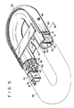
- a race track shaped winding former 50 has an arcuate sectional profile, more particularly a sectional profile resembling a letter C.
- the winding former 50 which is a hollow member of an arcuate profile, consists of a pipe member 52 of an arcuate profile open on the outer side and a member 54, having a rectangular channel-like sectional profile, integral with open edge portions of the pipe member 52.
- the sealed inner space 56 of the winding former 50 having the shape as described above, corresponds to a second space which serves as the coolant path.
- a plurality of metal plates 58 (only one such metal plate being made visible in Fig. 5), each having a shape corresponding to the section of the coolant path 56, are disposed in the path 56, whereby the path 56 is divided into a plurality of chambers by the metal plates 58.
- Each plate 58 is formed with holes 60. Through the holes 60, the coolant such as liquid helium which is not shown in Figs. 5 and 6 flows through the path 56.
- Reinforcing ribs 62 are provided on the innner surface of the channel-like member 54 of the winding former 50.
- the superconducting wire 16 is wound around the channel-like member 54 of the winding former 50.
- the wire 16 is impregnated with a hardenable material to obtain the superconducting coil structure 14.
- the outer open side 12 of the channel-like member 54 of the winding former 50 is closed by an outer cover member 64.
- a vessel 66 is, thus, constituted by the outer cover member 64 and winding former 50.
- the outer cover member 64 has a strip-like shape having a greater width than the width of the outer open side of the channel-like member 54 of the winding former 50, and its opposite edges are welded to the outer surface of the winding former 50.
- the outer cover member 64 and channel-like member 54 define the first space 65 in which the coil structure 14 is sealed. For the rest, the construction is the same as that of the previous embodiments and will not be described.
- the superconducting coil structure 14 is cooled at its three sides by liquid helium flowing through the cooling path 56.
- the efficiency of cooling the coil structure 14 can be further improved.
- the winding former 50 since the winding former 50 has a C-shaped sectional profile which is gently curved, it is tough and can be readily fabricated.
- the impregnation of the superconducting wire 16 is carried out after the welding of parts including the outer cover member 64 has been completed. More particularly, a hardenable material such as an epoxy resin is introduced into the vessel 66 through an injection port 48 provided on the outer cover member 64, while exhausting air in the space first space defined by the channel-like member 54 of the vessel 66 from an exhausting port (not shown).
- a hardenable material such as an epoxy resin is introduced into the vessel 66 through an injection port 48 provided on the outer cover member 64, while exhausting air in the space first space defined by the channel-like member 54 of the vessel 66 from an exhausting port (not shown).
- the wire structure 16 is impregnated with the hardenable material and immovably accommodated in the vessel 66.
- the method of manufacture can thus be greatly simplified, and also it is possible to prevent deterioration of the property of the coil 14 due to heat at the time of the welding, welding distortion or the like. It is thus possible to manufacture high quality superconducting magnets with high yield and
- the channel-like member 54 of the superconducting magnet shown in Figs. 5 and 6 has round corners 70 and 72 as shown in Fig. 7, metal plates 76, 77 and 78 consisting of copper material or the like are bonded to the three inner surfaces of the channel-like member 54. According to such the arrangement, the superconducting wire 16 can be wound in accurate alignment even at the corners of the channel-like member 54. At the same time, the conductivity of the coil structure can be improved, since the metal plates have the good conductivity characteristics.
Landscapes
- Engineering & Computer Science (AREA)
- Power Engineering (AREA)
- Containers, Films, And Cooling For Superconductive Devices (AREA)
- Superconductors And Manufacturing Methods Therefor (AREA)
- Manufacturing Cores, Coils, And Magnets (AREA)
Claims (14)
Applications Claiming Priority (4)
| Application Number | Priority Date | Filing Date | Title |
|---|---|---|---|
| JP16052381A JPS5861606A (ja) | 1981-10-08 | 1981-10-08 | 超電導電磁石装置 |
| JP160523/81 | 1981-10-08 | ||
| JP19443081A JPS5896704A (ja) | 1981-12-04 | 1981-12-04 | 超電導電磁石とその製造方法 |
| JP194430/81 | 1981-12-04 |
Publications (2)
| Publication Number | Publication Date |
|---|---|
| EP0076887A1 EP0076887A1 (fr) | 1983-04-20 |
| EP0076887B1 true EP0076887B1 (fr) | 1987-09-23 |
Family
ID=26487006
Family Applications (1)
| Application Number | Title | Priority Date | Filing Date |
|---|---|---|---|
| EP82102958A Expired EP0076887B1 (fr) | 1981-10-08 | 1982-04-06 | Aimant supraconducteur et sa méthode de fabrication |
Country Status (5)
| Country | Link |
|---|---|
| US (2) | US4549156A (fr) |
| EP (1) | EP0076887B1 (fr) |
| CA (1) | CA1175099A (fr) |
| DE (1) | DE3277392D1 (fr) |
| SU (1) | SU1403996A3 (fr) |
Families Citing this family (34)
| Publication number | Priority date | Publication date | Assignee | Title |
|---|---|---|---|---|
| US4622531A (en) * | 1985-04-26 | 1986-11-11 | Wisconsin Alumni Research Foundation | Superconducting energy storage magnet |
| US5089467A (en) * | 1987-07-29 | 1992-02-18 | Oregon Graduate Center | Superconductor structures and method of forming same |
| US4956740A (en) * | 1987-08-04 | 1990-09-11 | Massachusetts Institute Of Technology | Protection technique for superconducting magnets |
| US4979704A (en) * | 1989-01-23 | 1990-12-25 | Westinghouse Electric Corp. | Apparatus for retaining a superconducting cable in a coil stack |
| US4912444A (en) * | 1989-02-06 | 1990-03-27 | Westinghouse Electric Corp. | Superconducting solenoid coil structure with internal cryogenic coolant passages |
| US4920754A (en) * | 1989-02-06 | 1990-05-01 | Westinghouse Electric Corp. | System for dumping cryogens in a superconducting solenoid installation |
| US4912443A (en) * | 1989-02-06 | 1990-03-27 | Westinghouse Electric Corp. | Superconducting magnetic energy storage inductor and method of manufacture |
| US4969064A (en) * | 1989-02-17 | 1990-11-06 | Albert Shadowitz | Apparatus with superconductors for producing intense magnetic fields |
| US5404122A (en) * | 1989-03-08 | 1995-04-04 | Kabushiki Kaisha Toshiba | Superconducting coil apparatus with a quenching prevention means |
| US5065496A (en) * | 1989-06-01 | 1991-11-19 | Westinghouse Electric Corp. | Process for making a superconducting magnet coil assembly for particle accelerators |
| US5072516A (en) * | 1989-06-01 | 1991-12-17 | Westinghouse Electric Corp. | Apparatus and process for making a superconducting magnet for particle accelerators |
| US5065497A (en) * | 1989-06-01 | 1991-11-19 | Westinghouse Electric Corp. | Apparatus for making a superconducting magnet for particle accelerators |
| US5088184A (en) * | 1989-06-01 | 1992-02-18 | Westinghouse Electric Corp. | Process for making a superconducting magnet for particle accelerators |
| US5098276A (en) * | 1989-06-01 | 1992-03-24 | Westinghouse Electric Corp. | Apparatus for making a superconducting magnet for particle accelerators |
| US5094393A (en) * | 1989-06-01 | 1992-03-10 | Westinghouse Electric Corp. | Apparatus and process for making a superconducting magnet for particle accelerators |
| US5237738A (en) * | 1989-11-20 | 1993-08-24 | Advanced Cryo Magnetics, Inc. | Method of manufacturing a containment vessel for use with a pulsed magnet system |
| JP2539527B2 (ja) * | 1990-03-02 | 1996-10-02 | 株式会社日立製作所 | 超電導磁気浮上列車、超電導磁気浮上列車システム並びにその制御方法及び磁気浮上列車用超電導コイル |
| US5085149A (en) * | 1990-04-06 | 1992-02-04 | Houston Area Research Center | Ground vehicle suspension and guidance and electromagnetic system thereof with multiple surface arcuate reaction rails |
| US5115219A (en) * | 1990-06-04 | 1992-05-19 | Chicago Bridge And Iron Technical Services | Superconducting magnetic energy storage apparatus structural support system |
| JP2786330B2 (ja) * | 1990-11-30 | 1998-08-13 | 株式会社日立製作所 | 超電導マグネットコイル、及び該マグネットコイルに用いる硬化性樹脂組成物 |
| JP2982346B2 (ja) * | 1991-04-02 | 1999-11-22 | 住友電気工業株式会社 | 高温超電導コイル |
| JP2539121B2 (ja) * | 1991-09-19 | 1996-10-02 | 株式会社日立製作所 | 超伝導磁石 |
| WO1995006949A1 (fr) * | 1993-09-01 | 1995-03-09 | Grumman Aerospace Corporation | Electroaimant supraconducteur servant a la sustentation et a la propulsion d'un vehicule a sustentation magnetique |
| US5672921A (en) * | 1995-03-13 | 1997-09-30 | General Electric Company | Superconducting field winding assemblage for an electrical machine |
| KR100498972B1 (ko) * | 1997-08-05 | 2005-07-01 | 피렐리 카비 에 시스테미 소시에떼 퍼 아찌오니 | 고온 초전도 케이블과 그의 제조 방법 |
| GB2426630B (en) * | 2005-05-26 | 2007-11-21 | Siemens Magnet Technology Ltd | Electromagnet |
| US7705701B2 (en) * | 2005-07-15 | 2010-04-27 | General Electric Company | Thin metal layer vacuum vessels with composite structural support |
| GB0519882D0 (en) * | 2005-09-29 | 2005-11-09 | Oxford Instr Superconductivity | Superconducting electromagnet |
| GB2432259B (en) * | 2005-11-14 | 2008-01-30 | Siemens Magnet Technology Ltd | A resin-impregnated superconducting magnet coil comprising a cooling layer |
| JP6262417B2 (ja) * | 2012-07-31 | 2018-01-17 | 川崎重工業株式会社 | 磁場発生装置及びこれを備える超電導回転機 |
| CN106298148B (zh) * | 2015-05-11 | 2019-04-23 | 通用电气公司 | 超导磁体系统及冷却件 |
| CN106363349B (zh) * | 2016-08-29 | 2018-12-11 | 武汉一冶建筑安装工程有限责任公司 | 一种机械手环形轨道的加工方法 |
| US11442124B2 (en) * | 2019-09-26 | 2022-09-13 | Shanghai United Imaging Healthcare Co., Ltd. | Superconducting magnet |
| RU2758712C1 (ru) * | 2021-02-08 | 2021-11-01 | Объединенный Институт Ядерных Исследований | Каркас для сверхпроводящего соленоида |
Family Cites Families (7)
| Publication number | Priority date | Publication date | Assignee | Title |
|---|---|---|---|---|
| US3356976A (en) * | 1965-11-10 | 1967-12-05 | William B Sampson | Quadrupole magnet |
| GB1261597A (en) * | 1969-06-19 | 1972-01-26 | Imp Metal Ind Kynoch Ltd | Improvements in or relating to superconductors |
| DE1932086C3 (de) * | 1969-06-25 | 1976-01-08 | Siemens Ag, 1000 Berlin Und 8000 Muenchen | Aus Supraleitermaterial und bei der Betriebstemperatur des Supraleitermaterials elektrisch normalleitendem Metall zusammengesetzter Hohlleiter |
| US3720777A (en) * | 1971-08-25 | 1973-03-13 | Atomic Energy Commission | Low loss conductor for a.c.or d.c.power transmission |
| CH592946A5 (fr) * | 1975-12-15 | 1977-11-15 | Bbc Brown Boveri & Cie | |
| JPS561411A (en) * | 1979-05-18 | 1981-01-09 | Japan Atomic Energy Res Inst | Large capacity superconductor |
| JPS57166840A (en) * | 1981-04-02 | 1982-10-14 | Mitsubishi Electric Corp | Rotor for superconductive rotary electric machine |
-
1982
- 1982-03-31 US US06/363,888 patent/US4549156A/en not_active Expired - Fee Related
- 1982-04-06 EP EP82102958A patent/EP0076887B1/fr not_active Expired
- 1982-04-06 DE DE8282102958T patent/DE3277392D1/de not_active Expired
- 1982-04-14 CA CA000400931A patent/CA1175099A/fr not_active Expired
- 1982-04-15 SU SU823427391A patent/SU1403996A3/ru active
-
1984
- 1984-06-12 US US06/619,894 patent/US4640005A/en not_active Expired - Lifetime
Also Published As
| Publication number | Publication date |
|---|---|
| DE3277392D1 (en) | 1987-10-29 |
| EP0076887A1 (fr) | 1983-04-20 |
| US4640005A (en) | 1987-02-03 |
| US4549156A (en) | 1985-10-22 |
| CA1175099A (fr) | 1984-09-25 |
| SU1403996A3 (ru) | 1988-06-15 |
Similar Documents
| Publication | Publication Date | Title |
|---|---|---|
| EP0076887B1 (fr) | Aimant supraconducteur et sa méthode de fabrication | |
| JP2823412B2 (ja) | 電動機の冷却装置 | |
| EP0175495B1 (fr) | Appareil supraconducteur | |
| EP0487352A2 (fr) | Dispositif de bobine à supraconduction et procédé de sa fabrication | |
| US3869686A (en) | Super-conductive coils incorporating insulation between adjacent winding layers having a contraction rate matching that of the super-conductive material | |
| EP0011267B1 (fr) | Structure d'aimant supraconducteur | |
| US4328437A (en) | Superconductive exciter winding for a turbogenerator rotor | |
| CA1186944A (fr) | Enroulement electromagnetique pour organes de frappe sur imprimantes | |
| GB2432260A (en) | A resin-impregnated superconducting magnet coil and its method of manufacture which comprises a cooling layer and a filler layer. | |
| US5387889A (en) | Superconducting magnet apparatus | |
| Huke et al. | Design of a vertical wiggler with superconducting coils | |
| JP2755790B2 (ja) | 複合絶縁リアクトル | |
| JP3268047B2 (ja) | 超電導磁石装置 | |
| JPS59208811A (ja) | 超電導コイル | |
| JPH0333049Y2 (fr) | ||
| CN222851234U (zh) | 电感结构 | |
| JPH02228005A (ja) | 超電導コイルの製造方法 | |
| JP2868936B2 (ja) | 超電導磁石 | |
| JPS6119089B2 (fr) | ||
| JPS6156851B2 (fr) | ||
| JPH0746648B2 (ja) | 超電導コイル | |
| JPS6142403B2 (fr) | ||
| JPS6010592B2 (ja) | 核融合装置のポロイダル磁場コイル | |
| JP2642612B2 (ja) | 磁気浮上列車用超電導コイル装置 | |
| Elsel | Electric magnet with superconductive windings |
Legal Events
| Date | Code | Title | Description |
|---|---|---|---|
| PUAI | Public reference made under article 153(3) epc to a published international application that has entered the european phase |
Free format text: ORIGINAL CODE: 0009012 |
|
| AK | Designated contracting states |
Designated state(s): CH DE FR GB IT LI |
|
| 17P | Request for examination filed |
Effective date: 19830914 |
|
| RAP1 | Party data changed (applicant data changed or rights of an application transferred) |
Owner name: KABUSHIKI KAISHA TOSHIBA |
|
| RBV | Designated contracting states (corrected) |
Designated state(s): CH DE FR GB LI |
|
| GRAA | (expected) grant |
Free format text: ORIGINAL CODE: 0009210 |
|
| AK | Designated contracting states |
Kind code of ref document: B1 Designated state(s): CH DE FR GB LI |
|
| REF | Corresponds to: |
Ref document number: 3277392 Country of ref document: DE Date of ref document: 19871029 |
|
| ET | Fr: translation filed | ||
| PLBE | No opposition filed within time limit |
Free format text: ORIGINAL CODE: 0009261 |
|
| STAA | Information on the status of an ep patent application or granted ep patent |
Free format text: STATUS: NO OPPOSITION FILED WITHIN TIME LIMIT |
|
| 26N | No opposition filed | ||
| PGFP | Annual fee paid to national office [announced via postgrant information from national office to epo] |
Ref country code: GB Payment date: 19920320 Year of fee payment: 11 |
|
| PGFP | Annual fee paid to national office [announced via postgrant information from national office to epo] |
Ref country code: FR Payment date: 19920408 Year of fee payment: 11 |
|
| PGFP | Annual fee paid to national office [announced via postgrant information from national office to epo] |
Ref country code: CH Payment date: 19920416 Year of fee payment: 11 |
|
| PGFP | Annual fee paid to national office [announced via postgrant information from national office to epo] |
Ref country code: DE Payment date: 19920514 Year of fee payment: 11 |
|
| PG25 | Lapsed in a contracting state [announced via postgrant information from national office to epo] |
Ref country code: GB Effective date: 19930406 |
|
| PG25 | Lapsed in a contracting state [announced via postgrant information from national office to epo] |
Ref country code: LI Effective date: 19930430 Ref country code: CH Effective date: 19930430 |
|
| GBPC | Gb: european patent ceased through non-payment of renewal fee |
Effective date: 19930406 |
|
| PG25 | Lapsed in a contracting state [announced via postgrant information from national office to epo] |
Ref country code: FR Effective date: 19931229 |
|
| REG | Reference to a national code |
Ref country code: CH Ref legal event code: PL |
|
| PG25 | Lapsed in a contracting state [announced via postgrant information from national office to epo] |
Ref country code: DE Effective date: 19940101 |
|
| REG | Reference to a national code |
Ref country code: FR Ref legal event code: ST |