EP0076899A1 - Geschossfang - Google Patents
Geschossfang Download PDFInfo
- Publication number
- EP0076899A1 EP0076899A1 EP82107133A EP82107133A EP0076899A1 EP 0076899 A1 EP0076899 A1 EP 0076899A1 EP 82107133 A EP82107133 A EP 82107133A EP 82107133 A EP82107133 A EP 82107133A EP 0076899 A1 EP0076899 A1 EP 0076899A1
- Authority
- EP
- European Patent Office
- Prior art keywords
- slats
- row
- bullet trap
- target surface
- individual
- Prior art date
- Legal status (The legal status is an assumption and is not a legal conclusion. Google has not performed a legal analysis and makes no representation as to the accuracy of the status listed.)
- Granted
Links
Images


Classifications
-
- F—MECHANICAL ENGINEERING; LIGHTING; HEATING; WEAPONS; BLASTING
- F41—WEAPONS
- F41J—TARGETS; TARGET RANGES; BULLET CATCHERS
- F41J13/00—Bullet catchers
Definitions
- the present invention is based on a bullet trap according to the preamble of claim 1.
- DE-OS 28 39 509 discloses a bullet trap in which a plurality of bullet trap plates arranged one behind the other are provided, which consist, for example, of a hard rubber material. These bullet traps are suspended from the ceiling of the room, one behind the other, spaced apart from each other and parallel to the target surface.
- a disadvantage of such a known bullet trap is that its lifespan is relatively short because bullets penetrate primarily at one point, which leads to material being imposed at this point. This applies in particular to the front ball catcher plates.
- the object of the present invention is to provide a projectile trap which has a longer service life than the known projectile trap described above.
- a major advantage of the present invention is that projectiles hitting the individual lamellae do not penetrate them, but rather tumble back and forth between them and fall to the ground after braking.
- the lifespan of the bullet trap according to the invention is advantageously very long because many bullets do not penetrate the individual slats of the bullet trap.
- a projectile trap according to the invention approximately 80% of the projectiles are braked in such a way that they fall to the ground. Only about 20% get stuck.
- a bullet trap according to the invention can advantageously take up to 50,000 bullets per square meter.
- Another important advantage of the present invention is that no lead dust is produced, as is the case in particular with steel ball catches in which the projectiles hit steel surfaces directly.
- the bullet trap according to the invention can therefore prevent high levels of lead in the vicinity of the bullet trap which are harmful to health.
- the bullet trap according to the invention is advantageously suitable for the most varied calibers of handguns, hunting and police weapons.
- Another significant advantage of the present invention is that the projectiles that fall down generate very little noise due to the arrangement of the rows of slats.
- the sound emission of the bullet catches according to the invention is extremely low.
- no sound is transmitted to the walls surrounding the bullet trap, to which it is fastened, and to lines possibly present in these walls.
- a very important advantage of the present invention is the fact that the individual slats can be replaced very easily and quickly.
- the bullet catch according to the invention can therefore be serviced much more easily than known bullet catches.
- the projectile trap according to the invention can advantageously be shot from different directions due to the arrangement of the slats.
- a high impact safety is preferably provided in the projectile trap according to the invention.
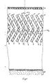
- Fig. 1 which shows a plan view of the section of a bullet trap according to the invention
- the target area is designated by 1.
- this target surface 1 is formed from a steel frame to which a Regupol layer is applied as the rear layer and a rubber foil as the front layer.
- a non-drying plastic plastic paste can be provided on the rubber film, which can easily recognize the hit pattern after a series of shots and can then be blurred again by a squeegee or the like.
- the lamella plates 5, 7, Arranged behind the target surface 1 in the manner shown in FIG. 1 are two rows of lamella plates 5, 7, which preferably consist of hard rubber.
- the lamella plates consist of a six-layer hard rubber material with multi-layer cast synthetic fiber mats or wire mesh.
- the rows of fins 5 and 7 are arranged obliquely to the target surface 1 in the manner shown in FIG. 1.
- the front plate plates 5 are arranged so that they form an angle ⁇ 1 to the normal of the target surface 1.
- the lamella plates 7 of the rear row form, for example, an angle to the normal to the target surface 1.
- the angles ⁇ 1 and ⁇ 2 run in opposite directions.
- the The angles ⁇ 1 and ⁇ 2 are the same size and are approximately 20-40 °.
- the angles ⁇ 1 and ⁇ 2 are preferably approximately 25 d or 30 °.
- the front plate plates 5 are inclined to the left by the angle ⁇ 1 with respect to the normal to the target surface 1, while the rear plate plates 7 are inclined to the right by the angle ⁇ 2 with respect to the normal to the target surface 1.
- the rear plate plates 7 are preferably arranged such that the front end of a rear plate plate 7 abuts the rear end of a front plate plate 5.
- channels 6, 8, which run in a zigzag shape, arise between the front plate row and the rear plate plate row, as shown in FIG. 1.
- Most of the sunken projectiles tumble back and forth in these channels. They are braked essentially in such a way that they fall down onto the floor perpendicular to the plane of the drawing.
- a space is provided behind the bullet trap for checking the bullet trapping condition and for clearing out the bullets.
- a rear wall 30 is preferably provided at a distance from the rear lamella plates 7.
- the distance of this rear wall 30, which is preferably made of sheet steel, is determined by the type of projectile, the projectile energy and the like.
- a steel wall 30 is expedient if projectiles are also used which, due to their weight, their energy and their construction, can pass through the rows of slats and reach the rear wall.
- a projectile running in the direction of the normal 2 to the target surface 1 strikes a front lamella plate 51 at point 9. If the weight of the projectile is sufficiently large, it can happen that the projectile penetrates the front lamella plate 51 at point 9 and exits the front lamella plate 51 at point 91. When penetration of the f orderen fin plate 51, the projectile is considerably decelerated.
- a projectile hitting from the firing direction 3 at an angle ⁇ to the normal passes, for example, through the channel formed by the front lamella plates 53 and 54 and hits the rear lamella plate 74 at location 111.
- the projectile penetrates the slat plate 74 at point 111, it tumbles back and forth in the channel formed by the rear slat plates 74 and 75. If the projectile is deflected at point 111 and does not penetrate the rear slat plate 74, it tumbles back and forth in the channel between the rear slat plates 73 and 74.
- a projectile hitting from the firing direction 4 at an angle ⁇ 'to the normal meets the front lamella plate 52 at location 121, for example.
- it Depending on whether or not it penetrates the front lamellar plate 52 at location 121, it subsequently tumbles either in the channel formed by the front lamellar plates 52 and 55 and the rear lamellar plates 72 and 76, or in the channel formed by the front slat plates 51 and 52 and the rear slat plates 71 and 72 is formed back and forth.
- the width of these slats is preferably about 25 cm, while the thickness is about 20 mm.
- the distance between the individual slats is about 30 mm.
- the individual front slat plates and the individual rear slat plates are each suspended in a freely swinging manner on a ceiling or on a frame provided for this purpose.
- the individual front and rear lamella plates are subdivided into a plurality of parallel sub-plates 5 ', 7', preferably into three parallel sub-plates.
- the partial plates each forming a lamella plate are preferably fastened to one another at their upper end by a suitable fastening device and suspended freely swinging on a ceiling or a frame provided for this purpose.
- Another advantage is that the maintenance of such a beffeen G eschoßfangs facilitated by usually not the entire lamella plates but often only the front sub-plates of the lamella plates facing the shooter have to be replaced. This can save costs. Projectiles that penetrate a lamella plate consisting of several parallel partial plates can, for example, after they have penetrated the front partial plate, tumble back and forth in the space between the front and the next partial plate and be braked in the process.
- the thickness of the individual partial plates can be, for example, approximately 10 mm.
- the individual lamella plates are preferably arranged on the side wall in such a way that they form an angle with the side wall point, which is determined depending on the dimensions of the shooting range.
Landscapes
- Engineering & Computer Science (AREA)
- General Engineering & Computer Science (AREA)
- Aiming, Guidance, Guns With A Light Source, Armor, Camouflage, And Targets (AREA)
Abstract
Description
- Die vorliegende Erfindung geht aus von einem Geschoßfang nach dem Oberbegriff des Patentanspruchs 1.
- Aus der DE-OS 28 39 509 (Fig. 11) ist ein Geschoßfang bekannt, bei dem hinter der Zielfläche mehrere hintereinander angeordnete Kugelfangplatten vorgesehen sind, die beispielsweise aus einem Hartgummiwerkstoff bestehen. Diese Kugelfangplatten sind parallel zur Zielfläche jeweils voneinander beabstandet hintereinander freihängend an der Decke des Raumes aufgehängt.
- Ein Nachteil eines solchen bekannten Geschoßfangs besteht darin, daß seine Lebensdauer verhältnismäßig klein ist, weil Geschosse vorwiegend an einer Stelle eindringen, was zu e'inem Ausschießen von Material an dieser Stelle führt. Dies gilt insbesondere für die vorderen Kugelfangplatten.
- Die Aufgabe der vorliegenden Erfindung besteht darin, einen Geschoßfang anzugeben, der eine größere Lebensdauer aufweist, als der zuvor beschriebene bekannte Geschoßfang.
- Dies* Aufgabe wird durch einen wie eingangs bereits erwähnten Geschoßfang gelöst, der durch die in dem kennzeichnenden Teil des Patentanspruchs 1 aufgeführten Merkmale gekennzeichnet ist.
- Ein wesentlicher Vorteil der vorliegenden Erfindung besteht darin, daß auf die einzelnen Lamellen auftreffende Geschosse diese nicht durchdringen, sondern zwischen ihnen hin und her taumeln und nach erfolgter Abbremsung zu Boden fallen. Vorteilhafterweise ist die Lebensdauer des erfindungsgemäßen Geschoßfangs sehr groß, weil viele Geschosse die einzelnen Lamellen des Geschoßfangs nicht durchdringen.
- Vorteilhafterweise werden bei einem erfindungsgemäßen Geschoßfang etwa 80 % der Geschosse derartig abgebremst, daß sie zu Boden fallen. Nur etwa 20 % bleiben stecken.
- Vorteilhafterweise kann ein erfindungsgemäßer Geschoßfang pro qm bis zu 50.000 Geschosse aufnehmen.
- Ein weiterer wesentlicher Vorteil der vorliegenden Erfindung besteht darin, daß kein Bleistaub entsteht, wie dies insbesondere bei Stahlkugelfängen der Fall ist, bei denen die Geschosse direkt auf Stahlflächen auftreffen. Durch den erfindungsgemäßen Geschoßfang können daher gesundheitsschädliche hohe Bleigehaltwerte in der Umgebung des Geschoßfangs vermieden werden.
- Vorteilhafterweise ist der erfindungsgemäße Geschoßfang für die unterschiedlichsten Kaliber von Faustfeuerwaffen, Jagd-und Polizeiwaffen geeignet.
- Ein weiterer wesentlicher Vorteil der vorliegenden Erfindung besteht darin, daß die einfallenden Geschosse infolge der Anordnung der Lamellenreihen sehr wenig Lärm erzeugen. Die Schallemission der erfindungsgemäßen Geschoßfänge ist äußerst gering. Es wird vorteilhafterweise kein Schall an die den Geschoßfang umgebenden Wände, an denen er befestigt ist und an ggfs. in diesen Wänden vorhandene Leitungen übertragen.
- Ein sehr wesentlicher Vorteil der vorliegenden Erfindung ist darin zu sehen, daß die einzelnen Lamellen sehr leicht und schnell ausgewechselt werden können. Der erfindungsgemäße Geschoßfang kann daher sehr viel einfacher gewartet werden als bekannte Geschoßfänge.
- 3 Vorteilhafterweise kann der erfindungsgemäße Geschoßfang infolge der Anordnung der Lamellen aus verschiedenen Richtungen angeschossen werden.
- Vorzugsweise ist bei dem erfindungsgemäßen Geschoßfang eine hohe Abprallsicherheit gegeben.
- Im folgenden werden die Erfindung und deren Ausgestaltungen im Zusammenhang mit den Figuren näher erläutert. Es zeigt:
- Fig. 1 und 2 einen erfindungsgemäßen Geschoßfang
- Fig. 3 eine Weiterbildung des erfindungsgemäßen Geschoßfangs und
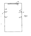
- Fig. 4 eine weitere Weiterbildung der Erfindung.
- In der Fig. 1, die eine Aufsicht auf den Schnitt eines erfindungsgemäßen Geschoßfangs zeigt, ist die Zielfläche mit 1 bezeichnet. Beispielsweise wird diese Zielfläche 1 aus einem Stahlrahmen gebildet, an dem als hintere Schicht eine Regupolschicht und als vordere Schicht eine Gummifolie angebracht sind. Auf der Gummifolie kann eine nichttrocknende plastische Kunststoffpaste vorgesehen sein, die nach einer Schußserie das Trefferbild leicht erkennen läßt, und anschließend durch ein Rakel oder dergl. wieder verwischbar ist.
- Hinter der Zielfläche 1 sind in der aus der Fig. 1 ersichtlichen Weise zwei Reihen von Lamellenplatten 5,7 angeordnet, die vorzugsweise aus Hartgummi bestehen. Insbesondere bestehen die Lamellenplatten aus einem sechslagigen Hartgummiwerkstoff mit mehrschichtig eingegossenen Kunstfasermatten oder Drahtgeflecht. Die Lamellenreihen 5 und 7 sind in der aus der Fig. 1 ersichtlichen Weise schräg zur Zielfläche 1 angeordnet. Beispielsweise sind die vorderen Lamellenplatten 5 so angeordnet, daß sie einen Winkel α1 zur Normalen der Zielfläche 1 bilden. Die Lamellenplatten 7 der hinteren Reihe bilden beispielsweise einen Winkele zur Normalen der Zielfläche 1. Die Winkel α1 und α2 verlaufen in entgegengesetzte Richtungen. Vorzugsweise sind die Winkel α1 und α2 gleich groß und betragen etwa 20 - 40°. Vorzugsweise betragen die Winkel α1 und α2 etwa 25doder 30°. Beispielsweise sind die vorderen Lamellenplatten 5 um den Winkel α1 gegenüber der Normalen zur Zielfläche 1 nach links geneigt, während die hinteren Lamellenplatten 7 gegenüber der Normalen zur Zielfläche 1 umd den Winkel α2 nach rechts geneigt sind.
- Die hinteren Lamellenplatten 7 sind vorzugsweise derart angeordnet, daß jeweils das vordere Ende einer hinteren Lamellenplatte 7 an das hintere Ende einer vorderen Lamellenplatte 5 anstößt. Auf diese Weise entstehen zwischen der vorderen Lamellenplattenreihe und der hinteren Lamellenplattenreihe zick-zack-förmig verlaufende Kanäle 6,8, wie dies in der Fig. 1 dargestellt ist. In diesen Kanälen taumeln die meisten der eingefallenen Geschosse hin und her. Dabei werden sie im wesentlichen derartig abgebremst, daß sie senkrecht zur Zeichenebene nach unten auf den Boden fallen. Hinter dem Geschoßfang ist ein Zwischenraum für die Kontrolle des Geschoßfangzustandes und für das Ausräumen der Geschosse vorgesehen.
- Von den hinteren Lamellenplatten 7 beabstandet ist vorzugsweise eine Rückwand 30 vorgesehen. Dabei wird der Abstand dieser Rückwand 30, die vorzugsweise aus Stahlblech besteht, von der Geschoßart, der Geschoßenergie und dergl. bestimmt. Insbesondere ist eine Stahlwand 30 dann zweckmäßig, wenn auch Geschosse verwendet werden, die auf Grund ihres Gewichtes, ihrer Energie und Konstruktion die Lamellenreihen passieren und zur Rückwand gelangen können.
- Im folgenden wird nun im Zusammenhang mit der Fig. 2 der Verlauf von aus verschiedenen Schußrichtungen 2 - 4 eintreffenden Geschossen beschrieben. Beispielsweise trifft ein in Richtung der Normalen 2 zur Zielfläche 1 verlaufendes Geschoß am Punkt 9 auf eine vordere Lamellenplatte 51 auf. Wenn die Wucht des Geschosses ausreichend groß ist, kann es geschehen, daß das Geschoß am Punkt 9 die vordere Lamellenplatte 51 durchdringt und am Punkt 91 aus der vorderen Lamellenplatte 51 wieder austritt. Beim Durchdringen der forderen Lamellenplatte 51 wird das Geschoß erheblich abgebremst. Es gelangt dann in den von den vorderen Lamellenplatten 51 und 52 und den hinteren Lamellenplatten 71 und 72 gebildeten Kanal und taumelt dort beispielsweise solange zwischen den vorderen Lamellenplatten 51, 52 und den hinteren Lamellenplatten 71, 72 hin und her (Punkte 91-94), bis es soweit abgebremst ist, daß es senkrecht nach unten auf den Boden fällt. Wenn die Wucht des aus der Richtung 2 eintreffenden Geschosses nicht so groß ist, daß es am Ort 9 die vordere Lamellenplatte 51 durchdringen kann, so taumelt das Geschoß in dem zwischen den vorderen Lamellenplatten 51 und 53 und den hinteren Lamellenplatten 71 und 73 gebildeten Kanal hin und her (Punkte 9 und 101 - 103). Wenn das Geschoß ausreichend abgebremst wurde, fällt es senkrecht nach unten.
- Ein aus der Schußrichtung 3 unter dem Winkel β zur Normalen auftreffendes Geschoß tritt beispielsweise durch den durch die vorderen Lamellenplatten 53 und 54 gebildeten Kanal hindurch und trifft am Ort 111 auf die hintere Lamellenplatte 74 auf. Wenn das Geschoß am Punkt 111 die Lamellenplatte 74 durchdringt, taumelt es in dem Kanal, der von den hinteren Lamellenplatten 74 und 75 gebildet wird, hin und her. Wenn das Geschoß am Punkt 111 abgelenkt wird und die hintere Lamellenplatte 74 nicht durchdringt, taumelt es in dem Kanal zwischen den hinteren Lamellenplatten 73 und 74 hin und her.
- Ein Aus der Schußrichtung 4 unter dem Winkel β' zur Normalen auftreffendes Geschoß trifft beispielsweise am Ort 121 auf die vordere Lamellenplatte 52 auf. Je nachdem, ob es am Ort 121 die vordere Lamellenplatte 52 durchdringt oder nicht, taumelt es anschließend entweder in dem Kanal, der durch die vorderen Lamellenplatten 52 und 55 und die hinteren Lamellenplatten 72 und 76 gebildet wird, oder in dem Kanal, der durch die vorderen Lamellenplatten 51 und 52 und die hinteren Lamellenplatten 71 und 72 gebildet wird, hin und her.
- Bei einem Anschußwinkel bis zu 25° ist eine Abprallsicherheit der auftreffenden Geschosse gewährleistet.
- Im folgenden wird ein Ausführungsbeispiel für die Bemessung der-einzelnen Lamellen angegeben. Vorzugsweise beträgt die Breite dieser Lamellen etwa 25 cm, während die Dicke etwa 20 mm beträgt. Der Abstand zwischen den einzelnen Lamellen beträgt etwa 30 mm.
- Vorzugsweise sind die einzelnen vorderen Lamellenplatten und die einzelnen hinteren Lamellenplatten jeweils freischwingend an einer Decke oder an einem hierzu vorgesehenen Rahmen aufgehängt.
- Bei einer Weiterbildung der vorliegenden Erfindung sind, wie dies aus der Fig. 3 ersichtlich ist, die einzelnen vorderen und hinteren Lamellenplatten in mehrere parallele Teilplat- ten 5', 7', vorzugsweise in drei parallele Teilplatten, unterteilt. Dabei sind vorzugsweise die jeweils eine Lamellenplatte bildenden Teilplatten an ihrem oberen Ende durch eine geeignete Befestigungseinrichtung aneinander befestigt und freischwingend an einer Decke oder einem hierzu vorgesehenen Rahmen aufgehägt. Ein Vorteil dieser Weiterbildung der Erfindung besteht darin, daß die für eine Lamellenplatte erforderliche Dicke dadurch erreicht wird, daß mehrere leichter verfügbare Teilplatten parallel zueinander angeordnet sind. Ein weiterer Vorteil besteht darin, daß die Wartung eines derartig beschaffenen Geschoßfangs dadurch erleichtert wird, daß zumeist nicht die gesamten Lamellenplatten, sondern häufig nur die dem Schützen zugewandten vorderen Teilplatten der Lamellenplatten ersetzt werden müssen. Hierdurch lassen sich Kosten einsparen. Geschosse, die in eine aus mehreren parallelen Teilplatten bestehende Lamellenplatte eindringen, können beispielsweise nachdem sie die vordere Teilplatte durchschlagen haben, in dem Zwischenraum zwischen der vorderen und der nächstfolgenden Teilplatte hin und her taumeln und dabei abgebremst werden. Die Dicke der einzelnen Teilplatten kann beispielsweise etwa 10 mm betragen.
- Prüfergebnisse haben gezeigt, daß erfindungsgemäße Geschoßfänge geeignet sind, die von Faustfeuerwaffen oder von Büchsen und Flinten abgefeuerten Geschosse der unterschiedlichsten Kaliber wirksam abzubremsen.
- In der Fig. 4 ist eine Weiterbildung der Erfindung dargestellt, bei der an den Seitenwänden 10 einer Schießhalle voneinander beabstandete Lamellenplatten 52' vor dem Geschoßfang bzw. der Zielfläche 1 derart angebracht sind, daß auf sie eintreffende Geschosse in den Zwischenraum zwischen den einzelnen Lamellenplatten in Richtung auf die Seitenwand gelenkt und dabei abgebremst werden. Vorzugsweise sind in der aus der Fig. 4 ersichtlichen Weise die einzelnen Lamellenplatten an der Seitenwand derart angeordnet, daß sie zur Seitenwand einen Winkel aufweisen, der in Abhängigkeit von den Abmessungen der Schießhalle bestimmt wird. Insbesondere ist es sinnvoll, derartige Lamellenplatten 52' an den Seitenwänden 10 einer Schießhalle im Bereich der Zielfläche 1 anzubringen.
Claims (14)
Applications Claiming Priority (2)
| Application Number | Priority Date | Filing Date | Title |
|---|---|---|---|
| DE3131228 | 1981-08-06 | ||
| DE3131228A DE3131228C2 (de) | 1981-08-06 | 1981-08-06 | Geschoßfang |
Publications (2)
| Publication Number | Publication Date |
|---|---|
| EP0076899A1 true EP0076899A1 (de) | 1983-04-20 |
| EP0076899B1 EP0076899B1 (de) | 1987-01-21 |
Family
ID=6138777
Family Applications (1)
| Application Number | Title | Priority Date | Filing Date |
|---|---|---|---|
| EP82107133A Expired EP0076899B1 (de) | 1981-08-06 | 1982-08-06 | Geschossfang |
Country Status (3)
| Country | Link |
|---|---|
| US (1) | US4458901A (de) |
| EP (1) | EP0076899B1 (de) |
| DE (1) | DE3131228C2 (de) |
Cited By (1)
| Publication number | Priority date | Publication date | Assignee | Title |
|---|---|---|---|---|
| AT2441U1 (de) * | 1998-04-09 | 1998-10-27 | Pitzinger Bautraeger U Projekt | Stahllamellen-geschossfang |
Families Citing this family (30)
| Publication number | Priority date | Publication date | Assignee | Title |
|---|---|---|---|---|
| DE3209644A1 (de) * | 1982-03-17 | 1983-09-29 | Roland 6300 Gießen Jankofsky | Kugelfang fuer schiessstaende |
| DE3733926A1 (de) * | 1987-10-07 | 1989-04-20 | Wojcinski Allen Stefan Dipl In | Geschossfangrahmen |
| US4819946A (en) * | 1987-10-07 | 1989-04-11 | Kahler James E | Bullet trap |
| US5607163A (en) * | 1990-01-19 | 1997-03-04 | Caswell International Corporation | Granulate backstop assembly |
| EP0438175A3 (en) * | 1990-01-19 | 1993-10-20 | Wojcinski Allan Stefan Dipl In | Bullet catcher filled with granular material |
| DE9017946U1 (de) * | 1990-07-13 | 1993-05-27 | BKE Bildtechnik, Inhaber Ernst Stechemesser, 3412 Nörten-Hardenberg | Kugelfanganlage |
| US5848794A (en) | 1991-01-18 | 1998-12-15 | Caswell International Corporation | Granulate backstop assembly |
| US5618044A (en) * | 1994-09-30 | 1997-04-08 | Bateman; Kyle E. | Bullet trap and containment cavity |
| DE29513567U1 (de) * | 1994-12-07 | 1995-10-26 | PVS GmbH Planung und Vertrieb von Schießanlagen, 10435 Berlin | Geschoßfangvorrichtung |
| US6173956B1 (en) | 1996-09-27 | 2001-01-16 | O.M.F. Inc. | Projectile backstop assembly |
| US5988647A (en) * | 1997-01-29 | 1999-11-23 | Superior Tire And Rubber Corporation | Bullet trap |
| US5901960A (en) * | 1998-01-13 | 1999-05-11 | Caswell International Corporation | Granulate-backstop assembly |
| US6378870B1 (en) | 1999-12-24 | 2002-04-30 | Action Target, Inc. | Apparatus and method for decelerating projectiles |
| US6533280B1 (en) | 2000-03-03 | 2003-03-18 | H. Addison Sovine | Bullet backstop assembly |
| US7194944B2 (en) | 2001-12-12 | 2007-03-27 | Action Target, Inc. | Bullet trap |
| US7775526B1 (en) | 2001-12-12 | 2010-08-17 | Action Target Inc. | Bullet trap |
| DE10221527B4 (de) * | 2002-05-14 | 2004-05-06 | Heinz Gruber | Geschossfangeinrichtung und Vorrichtung zur Durchführung von Wartungsarbeiten an derselben |
| US7621209B2 (en) * | 2002-07-12 | 2009-11-24 | Action Target Acquisition Crop. | Modular ballistic wall |
| US20050034594A1 (en) * | 2002-09-17 | 2005-02-17 | Parks Jimmy A. | Projectile retrieval system |
| US7134233B1 (en) * | 2003-10-01 | 2006-11-14 | The United States Of America As Represented By The Secretary Of The Army | Acoustically tuned cartridge casing catcher |
| US20060107985A1 (en) * | 2004-04-13 | 2006-05-25 | Sovine H A | Modular shoot house facility |
| US7175181B1 (en) | 2004-06-17 | 2007-02-13 | Action Target, Inc. | Portable shooting target |
| US8469364B2 (en) | 2006-05-08 | 2013-06-25 | Action Target Inc. | Movable bullet trap |
| KR101087283B1 (ko) * | 2008-12-24 | 2011-11-29 | 오인규 | 탄두 회수 장치 |
| US20110062667A1 (en) * | 2009-09-14 | 2011-03-17 | Jose Medina | Reality based training target trap |
| US20110233869A1 (en) * | 2010-03-25 | 2011-09-29 | John Ernest M | Ballistic paneling for bullet traps |
| US8827273B2 (en) | 2010-08-02 | 2014-09-09 | Action Target Inc. | Clearing trap |
| US10371489B2 (en) | 2016-01-15 | 2019-08-06 | Action Target Inc. | Bullet deceleration tray damping mechanism |
| GR1009336B (el) * | 2016-02-25 | 2018-07-31 | Νικολαος Κωνσταντινου Σουκος | Οικολογικος πινακας εκπαιδευσης σκοποβολης παντος τυπου και διαμετρηματος πυρομαχικων |
| US10030945B1 (en) * | 2017-05-30 | 2018-07-24 | Gary R. Mol | Bullet trapping apparatus |
Citations (5)
| Publication number | Priority date | Publication date | Assignee | Title |
|---|---|---|---|---|
| DE1273374B (de) * | 1965-06-05 | 1968-07-18 | Kloeckner Werke Ag | Geschossfangkammer |
| CH480610A (de) * | 1967-11-28 | 1969-10-31 | Stahlton Ag | Schiessanlage mit Anordnung zur Abschirmung der Gefahrenzone gegen Geschosse |
| DE2616213A1 (de) * | 1976-04-13 | 1977-11-03 | Hans Arnold Raadschelders | Schiesstand, insbesondere fuer schausteller |
| DE2839509A1 (de) * | 1978-09-11 | 1980-04-24 | Allan Stefan Wojcinski | Schiessanlage |
| GB2042142A (en) * | 1979-02-14 | 1980-09-17 | Taylor R S | Improvements in back stops |
Family Cites Families (10)
| Publication number | Priority date | Publication date | Assignee | Title |
|---|---|---|---|---|
| DE500781C (de) * | 1930-06-25 | Severin Robkiewicz Jun | Kugelfangtrichter | |
| GB190217036A (en) * | 1902-08-01 | 1903-06-11 | William Alexander Wetherall | Improvements relating to Bullet Screens |
| DE496873C (de) * | 1929-01-06 | 1930-04-28 | Abtlg Nuernberg Vorm H Utendoe | Kugelfang, insbesondere fuer Kleinkaliber-Geschosse |
| US2201527A (en) * | 1938-10-26 | 1940-05-21 | Howard L Freeman | Target and projectile receiver |
| US2420304A (en) * | 1944-05-05 | 1947-05-13 | Donald T Diem | Spent bullet trap |
| DE858951C (de) * | 1951-07-20 | 1952-12-11 | Adolf Ruhmschoettel | Kugelfangkasten fuer Schiessstaende |
| US2772092A (en) * | 1954-02-17 | 1956-11-27 | Nikoden Joseph | Bullet traps |
| US2818729A (en) * | 1955-07-15 | 1958-01-07 | Ralph M Ferguson | Bullet trap |
| US3701532A (en) * | 1970-10-07 | 1972-10-31 | Detroit Bullet Trap Corp | Bullet deflection apparatus |
| US3720411A (en) * | 1971-03-08 | 1973-03-13 | Vogelaere G De | Portable target to receive, contain, and prevent splashback of medium velocity projectiles |
-
1981
- 1981-08-06 DE DE3131228A patent/DE3131228C2/de not_active Expired
-
1982
- 1982-08-06 EP EP82107133A patent/EP0076899B1/de not_active Expired
- 1982-08-06 US US06/406,040 patent/US4458901A/en not_active Expired - Lifetime
Patent Citations (5)
| Publication number | Priority date | Publication date | Assignee | Title |
|---|---|---|---|---|
| DE1273374B (de) * | 1965-06-05 | 1968-07-18 | Kloeckner Werke Ag | Geschossfangkammer |
| CH480610A (de) * | 1967-11-28 | 1969-10-31 | Stahlton Ag | Schiessanlage mit Anordnung zur Abschirmung der Gefahrenzone gegen Geschosse |
| DE2616213A1 (de) * | 1976-04-13 | 1977-11-03 | Hans Arnold Raadschelders | Schiesstand, insbesondere fuer schausteller |
| DE2839509A1 (de) * | 1978-09-11 | 1980-04-24 | Allan Stefan Wojcinski | Schiessanlage |
| GB2042142A (en) * | 1979-02-14 | 1980-09-17 | Taylor R S | Improvements in back stops |
Cited By (1)
| Publication number | Priority date | Publication date | Assignee | Title |
|---|---|---|---|---|
| AT2441U1 (de) * | 1998-04-09 | 1998-10-27 | Pitzinger Bautraeger U Projekt | Stahllamellen-geschossfang |
Also Published As
| Publication number | Publication date |
|---|---|
| DE3131228A1 (de) | 1983-03-03 |
| DE3131228C2 (de) | 1986-08-07 |
| US4458901A (en) | 1984-07-10 |
| EP0076899B1 (de) | 1987-01-21 |
Similar Documents
| Publication | Publication Date | Title |
|---|---|---|
| EP0076899B1 (de) | Geschossfang | |
| DE2845431C1 (de) | Wuchtgeschoss | |
| EP0311123A2 (de) | Geschossfangrahmen | |
| DE3209644C2 (de) | ||
| EP3719439B1 (de) | Geschossfang | |
| DE1553994A1 (de) | Kurzstreckengeschuetz fuer nicht gelenkte Geschosse | |
| DE4022327C2 (de) | Geschoßfangeinrichtung | |
| DE2906378C1 (de) | Aktive Schutzvorrichtung fuer feste oder bewegliche Objekte | |
| DE4237798C2 (de) | Panzerung | |
| DE3418626A1 (de) | Schichtfolge zur abprallsicherung | |
| DE3515726A1 (de) | Material mit hoher widerstandskraft | |
| DE4436060B4 (de) | Geschossfangeinrichtung für Innen- und Außenraum-Einsatz | |
| DE3842677C1 (de) | Aktive Vorpanzerung vor einer zu schützenden Panzerwand | |
| DE1135342B (de) | Mehrschichtiges zusammengesetztes Gebilde zur Panzerung gegen Beschuss oder Schlag | |
| DE2932778A1 (de) | Schiess- und auffangscheiben | |
| DE3904293A1 (de) | Flaechenwaffe | |
| DE3819251A1 (de) | Vielfachgeschoss | |
| DE10221527B4 (de) | Geschossfangeinrichtung und Vorrichtung zur Durchführung von Wartungsarbeiten an derselben | |
| DE4122877A1 (de) | Vorrichtung zur vermeidung von geschossabprallern | |
| DE19749881A1 (de) | Geschoßfangeinrichtung | |
| DE19613723C1 (de) | Umhauste Anlage für das sportliche und/oder jagdliche und/oder behördliche Schießen mit Schußwaffen | |
| DE3239759A1 (de) | Transportabler einzel-schiessstand | |
| AT155846B (de) | Durchschußrahmen für Einrichtungen zur Bestimmung der Geschoßgeschwindigkeiten und Streuungsbilder. | |
| DE102004010636A1 (de) | Geschossfangvorrichtung | |
| DE3900864A1 (de) | Kugelfang-anlage |
Legal Events
| Date | Code | Title | Description |
|---|---|---|---|
| PUAI | Public reference made under article 153(3) epc to a published international application that has entered the european phase |
Free format text: ORIGINAL CODE: 0009012 |
|
| AK | Designated contracting states |
Designated state(s): FR GB IT |
|
| 17P | Request for examination filed |
Effective date: 19831019 |
|
| GRAA | (expected) grant |
Free format text: ORIGINAL CODE: 0009210 |
|
| AK | Designated contracting states |
Kind code of ref document: B1 Designated state(s): FR GB IT |
|
| ITF | It: translation for a ep patent filed | ||
| ET | Fr: translation filed | ||
| PLBE | No opposition filed within time limit |
Free format text: ORIGINAL CODE: 0009261 |
|
| STAA | Information on the status of an ep patent application or granted ep patent |
Free format text: STATUS: NO OPPOSITION FILED WITHIN TIME LIMIT |
|
| 26N | No opposition filed | ||
| PGFP | Annual fee paid to national office [announced via postgrant information from national office to epo] |
Ref country code: FR Payment date: 19890814 Year of fee payment: 8 |
|
| ITTA | It: last paid annual fee | ||
| PGFP | Annual fee paid to national office [announced via postgrant information from national office to epo] |
Ref country code: GB Payment date: 19890831 Year of fee payment: 8 |
|
| PG25 | Lapsed in a contracting state [announced via postgrant information from national office to epo] |
Ref country code: GB Effective date: 19900806 |
|
| GBPC | Gb: european patent ceased through non-payment of renewal fee | ||
| PG25 | Lapsed in a contracting state [announced via postgrant information from national office to epo] |
Ref country code: FR Effective date: 19910430 |
|
| REG | Reference to a national code |
Ref country code: FR Ref legal event code: ST |