EP0077012B1 - Ensemble coulissant à position d'équilibre instable - Google Patents
Ensemble coulissant à position d'équilibre instable Download PDFInfo
- Publication number
- EP0077012B1 EP0077012B1 EP19820109222 EP82109222A EP0077012B1 EP 0077012 B1 EP0077012 B1 EP 0077012B1 EP 19820109222 EP19820109222 EP 19820109222 EP 82109222 A EP82109222 A EP 82109222A EP 0077012 B1 EP0077012 B1 EP 0077012B1
- Authority
- EP
- European Patent Office
- Prior art keywords
- sleeve
- element according
- resp
- sleeves
- slideable element
- Prior art date
- Legal status (The legal status is an assumption and is not a legal conclusion. Google has not performed a legal analysis and makes no representation as to the accuracy of the status listed.)
- Expired
Links
- 229910000831 Steel Inorganic materials 0.000 claims description 4
- 238000006073 displacement reaction Methods 0.000 claims description 4
- 239000010959 steel Substances 0.000 claims description 4
- 229910000639 Spring steel Inorganic materials 0.000 claims description 3
- 238000005452 bending Methods 0.000 claims description 3
- 239000000463 material Substances 0.000 claims description 3
- 239000012858 resilient material Substances 0.000 claims description 3
- 210000000078 claw Anatomy 0.000 claims description 2
- 244000166490 Tetrameles nudiflora Species 0.000 claims 1
- 238000005096 rolling process Methods 0.000 description 47
- 230000005540 biological transmission Effects 0.000 description 3
- 238000003780 insertion Methods 0.000 description 3
- 230000037431 insertion Effects 0.000 description 3
- 238000004519 manufacturing process Methods 0.000 description 3
- 230000007935 neutral effect Effects 0.000 description 3
- 241000209035 Ilex Species 0.000 description 2
- 230000008901 benefit Effects 0.000 description 2
- 238000000034 method Methods 0.000 description 2
- 239000004753 textile Substances 0.000 description 2
- 229910001369 Brass Inorganic materials 0.000 description 1
- 230000015572 biosynthetic process Effects 0.000 description 1
- 239000010951 brass Substances 0.000 description 1
- 238000010276 construction Methods 0.000 description 1
- 238000005553 drilling Methods 0.000 description 1
- 230000005489 elastic deformation Effects 0.000 description 1
- 238000002347 injection Methods 0.000 description 1
- 239000007924 injection Substances 0.000 description 1
- 238000003754 machining Methods 0.000 description 1
- 238000011089 mechanical engineering Methods 0.000 description 1
- 238000003860 storage Methods 0.000 description 1
Images

Classifications
-
- F—MECHANICAL ENGINEERING; LIGHTING; HEATING; WEAPONS; BLASTING
- F16—ENGINEERING ELEMENTS AND UNITS; GENERAL MEASURES FOR PRODUCING AND MAINTAINING EFFECTIVE FUNCTIONING OF MACHINES OR INSTALLATIONS; THERMAL INSULATION IN GENERAL
- F16H—GEARING
- F16H63/00—Control outputs from the control unit to change-speed- or reversing-gearings for conveying rotary motion or to other devices than the final output mechanism
- F16H63/02—Final output mechanisms therefor; Actuating means for the final output mechanisms
- F16H63/30—Constructional features of the final output mechanisms
-
- F—MECHANICAL ENGINEERING; LIGHTING; HEATING; WEAPONS; BLASTING
- F16—ENGINEERING ELEMENTS AND UNITS; GENERAL MEASURES FOR PRODUCING AND MAINTAINING EFFECTIVE FUNCTIONING OF MACHINES OR INSTALLATIONS; THERMAL INSULATION IN GENERAL
- F16C—SHAFTS; FLEXIBLE SHAFTS; ELEMENTS OR CRANKSHAFT MECHANISMS; ROTARY BODIES OTHER THAN GEARING ELEMENTS; BEARINGS
- F16C29/00—Bearings for parts moving only linearly
- F16C29/04—Ball or roller bearings
-
- F—MECHANICAL ENGINEERING; LIGHTING; HEATING; WEAPONS; BLASTING
- F16—ENGINEERING ELEMENTS AND UNITS; GENERAL MEASURES FOR PRODUCING AND MAINTAINING EFFECTIVE FUNCTIONING OF MACHINES OR INSTALLATIONS; THERMAL INSULATION IN GENERAL
- F16H—GEARING
- F16H63/00—Control outputs from the control unit to change-speed- or reversing-gearings for conveying rotary motion or to other devices than the final output mechanism
- F16H63/02—Final output mechanisms therefor; Actuating means for the final output mechanisms
- F16H63/30—Constructional features of the final output mechanisms
- F16H2063/3079—Shift rod assembly, e.g. supporting, assembly or manufacturing of shift rails or rods; Special details thereof
Definitions
- the invention relates to a sliding element with an inner sleeve and an outer sleeve overlapping and adapted to it in cross-section, at least one sleeve having longitudinally running rolling element tracks, in which the sleeves are spaced rolling elements and the sleeves axially to one another between two End positions are displaceable.
- Sliding elements for guiding push rods are often used for control in mechanical engineering.
- a common technique is that round-cut shift rods with an exact diameter are guided in slide bushes of the appropriate caliber, each push rod preferably being held by two slide bushes.
- the invention begins, which is based on the object of specifying a generic sliding element which has a position which corresponds to an unstable equilibrium, with a slight movement leading from this position causing the sliding element to jump into the end position which corresponds to the direction of movement Consequence.
- the position of the position that corresponds to the unstable equilibrium should be selectable;
- the sliding element should be free of play, reliable and economically producible.
- Rolling element bearings for longitudinal displacements are known from the prior art (US Pat. No. 3,353,876), in which friction between the longitudinally displacing parts against one another is to be reduced.
- An inner bearing sleeve with a circular cross section is made of resilient material and provided with a continuous longitudinal slot. This enables the bearing bush to be bent together during assembly so that it can be inserted between the rows of rolling elements, which are evenly distributed over the circumference and which are inserted into the outer rigid bearing bush, and then under their spring action the rows of rolling elements into the corresponding guideways in of the outer and inner bushes and holds there.
- the rolling elements are evenly distributed over the entire circumference of the cylindrical bearing bushes, and they are arranged in greater numbers in each track, and in particular the inner resilient bearing bushing is to be placed flat on the inner guide rod of the parts which are displaceable against one another.
- Such a rolling element bearing is intended for the transmission of forces for guidance, for preventing sliding friction and for centering the parts which are movable relative to one another. The above task is not affected by this state of the art.
- a generic sliding element is characterized in that at least one of the two sleeves consists of a resilient material, has a continuous longitudinal slot and is resiliently resilient transversely to the longitudinal direction and that in the resilient sleeve is approximately equally far from the longitudinal slot mutually opposite tracks are formed, in which at most two rolling elements are arranged, so that the sleeves automatically snap after moving from one end position beyond the central position into the other end position.
- This configuration forms a sliding element which has a position corresponding to an unstable equilibrium position if, for example, the outer sleeve is inserted in a form-fitting manner in a mounting plate fixed to the frame.
- the position of this position of the unstable equilibrium can be influenced by the position of the encircling point: if the mounting plate fixed to the frame surrounds the sleeve in a form-fitting manner in the middle, the position of the position of the unstable equilibrium is in the center. With side shift the position of the position of the unstable equilibrium is shifted to this side.
- the length of the distance which is necessary to bring the displaceable sleeve out of the position of the unstable equilibrium depends on the pressure exerted on the resilient element by the form-fitting enclosure, the position of the enclosure determining the position of this position . It also depends on the number of rolling elements in the rolling element spaces. If there is one rolling element in the rolling element space, this position of the unstable equilibrium is very narrowly limited. With two rolling elements arranged there, the necessary length of the sliding movement, which leads out of the unstable equilibrium, becomes greater. The same can also be achieved if the distance between the rolling elements is increased. If only one sliding element is used, it is recommended to provide two rolling elements in each rolling element space. This reduces the risk of tipping over.
- two rolling elements are therefore arranged at a distance from one another in a track.
- Corresponding tracks for the rolling elements can also be formed in both sleeves. It is advantageous if both sleeves are resilient and each have a longitudinal slot.
- the rolling elements can be balls, they can also be designed as rollers.
- the formation of these parts as commercially available parts ensures that the sliding element can be manufactured economically.
- the cross-sectional shape of the outer sleeve essentially corresponds to a circular cross-section with flattened sides.
- Such an outer sleeve is easy to insert into a corresponding hole, which represents a breakthrough in a housing.
- the outer sleeve expediently has cam-shaped bends at two opposite corners of the slot. These bends serve to fix the sliding element, for this purpose the bore or the cylindrical hole in the wall of the housing is provided with a groove through which a bent cam is guided. After inserting the sliding element, it can then be rotated so that both cam-shaped bends lie against the bushing wall and block the outer sleeve with regard to possible longitudinal movements.
- the cross-sectional shape of the inner sleeve expediently corresponds to a rectangular shape, the four edges of the inner sleeve being provided with rounded edge deformations which extend over the entire length of the sleeve and are directed toward the inside of the sleeve.
- This choice of the cross section of the inner sleeve makes it possible to use displaceable shift rods with a rectangular cross section.
- this sleeve shape has the essential advantage that the rectangular shift rods used can be used in such a way that the two side parts with the rolling element tracks are exposed. This allows an elastic deformation of these side parts without having to work out the shift rod in this area.
- the stability of the inner sleeve is significantly increased by the selection of this cross section, which benefits the operational reliability of the sliding element.
- At least one sleeve is expediently made of steel, preferably of spring steel. At least one sleeve can be made by angling and bending tape material.
- the spring steel sleeve ensures its elasticity; the mode of operation of the sliding element is ensured by its own internal elasticity. Since the operation of the sliding element is based on only slight deformations of one of the sleeves or their wall parts, it is not necessary that these sleeves are made of particularly high quality spring steels. The slight deformations on which the operation of the sliding element is based also exceed for steel, spring brass or the like. not the limits of the elastic range, an inelastic deformation is not to be feared.
- At least one sleeve of the sliding element is a plastic part, preferably an injection molded part.
- the raceways are limited according to the invention at least in one direction, the outer sleeves are supported in the walls and the inner sleeves are coupled to the shift rod.
- switching devices preferably for textile machines and / or mechanical drives, for example motor vehicle transmissions, in which disengagement, switching or other switching movements associated with pushing movement are to be carried out.
- the shift rods are properly guided by the play-free sliding elements; the switching paths can be limited; A neutral position corresponding to an unstable balance also allows the use of sliding sleeves if both end positions of the shift rod are required as shift positions.
- the inner sleeve can also be the selector rod itself, which is provided with corresponding rolling element tracks and over which the outer sleeve is inserted before being introduced into the form-fitting enclosure.
- the outer sleeve allows such a deformation due to its slot and its elasticity.
- FIG. 1 shows a perspective schematic representation of an embodiment of the sliding element according to the invention.
- This sliding element 10 is inserted into the mounting wall 1 of a housing, approximately in the middle.
- the mounting wall 1 has an opening adapted to the shape of the sliding element, in which the sliding element is held in a form-fitting manner.
- the top of the sliding element 10 is curved; it merges into the straight side walls which are bent at their lower end and which are provided with the rolling element tracks 11.
- the inner sleeve 20 is arranged, the corresponding sides 22 of which are provided with roller body tracks 21 expressed in opposite directions. As shown, both sleeves 10 and 20 are slotted in the longitudinal direction.
- the slot 30 of the inner sleeve 20 has a small width; the slot 40 of the outer sleeve 10 is disproportionately wider.
- the slot 30 of the inner sleeve 20 is widened when a rectangular shift rod is inserted in a positive manner.
- form-fitting refers only to the rectangular space located between the lower and the upper parts of the inner sleeve 20.
- the expressed sides 22 - into which the rolling element tracks are incorporated towards the inside, are hollow opposite the shift rod.
- FIGS 2 and 3 show a front view and a side view of the sliding element according to the invention.
- the housing wall 1 has been omitted in FIG. 2 for the sake of clarity.
- the outer sleeve 10 has an approximately U-shaped shape, the edges facing the open side of the U being provided with bends 13.
- the inner sleeve 20 is rectangular in its basic shape; the opposite side walls 22, which correspond to the flat walls of the U-shaped outer sleeve 10, are expressed in relation to the rectangular shape.
- a rolling element track 21 and the corresponding rolling element path 11 each form a rolling element space; Rolling elements 12 are provided in each of the rolling element spaces.
- the side view shows this in a similar way: in the housing wall 1 there is the outer sleeve 10, in which the inner sleeve 20 is in its neutral position. On average, only one of the rolling element tracks, namely the rolling element track 21 of the inner sleeve, can be seen; the hidden rolling elements 12 are indicated by dashed lines.
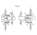
- FIG. 4 shows an embodiment in which a sliding element is provided in two housing walls 1.
- the shift rod 3 with a drive, not shown, lying outside the figure is shifted by a certain path length. In the illustration, it is in its left stop position, this can be seen from the position of the inner sleeve 20 relative to the outer sleeve 10, the rolling elements 12 having arrived at the end of the rolling element path in the sleeve shown on the left. In this position, one of the engagement forks 4 is in the engaged state and interacts with the mechanical element (not shown) to be switched. If the shift rod 3 is moved to the right, it reaches its neutral position, from which, if it moves in the same direction, it jumps to the other end position.
- the rolling elements 12 of the right sliding element lie against the end of the rolling element path 11 of this sliding element.
- the mounting walls 1 are provided with a receiving cone which has a circular cross section.
- This design allows the sliding elements to be fixed by means of integrally formed cams 13.
- a groove 2.1 is provided in the bore. The cam to be fixed on the opposite side is pushed through this groove; after pushing through the outer sleeve, it is rotated and both cams block the further longitudinal movement of the outer sleeve.
- the sliding element according to the invention is extremely versatile. It is not absolutely necessary that the form fit of the outer sleeve with the mounting plate must be given around the entire circumference. Rather, it is advantageous to remove the side walls provided with the rolling element tracks in a free-standing manner from the positive connection.
- a preferred embodiment of the recess is that this recess represents the exact circumference for the outer sleeve of the sliding element. This means that the straight side walls are free from the start and there is space for the rolling element tracks.
- Recesses with a circular cross section are made by drilling, if necessary also with reworking in a simple manner and thus economically producible.
- the longitudinal gap of the inner sleeve is also important: If the shift rod is not inserted, both sides are supported against each other, the gap width is close to zero. Nevertheless, the inner sleeve cannot be deformed to such an extent that the rolling elements can fall out of the rolling element space. This gap also allows an undersize of the receiving cross section for the shift rod; the positive insertion of the shift rod then only results in the gap opening. Compliance with extremely precise dimensions and small tolerances is therefore superfluous.
Landscapes
- Engineering & Computer Science (AREA)
- General Engineering & Computer Science (AREA)
- Mechanical Engineering (AREA)
- Bearings For Parts Moving Linearly (AREA)
Claims (14)
Applications Claiming Priority (2)
| Application Number | Priority Date | Filing Date | Title |
|---|---|---|---|
| DE19813140587 DE3140587A1 (de) | 1981-10-13 | 1981-10-13 | Schiebeelement mit einer, einem labilen gleichgewicht entsprechender position, deren lage einstellbar ist |
| DE3140587 | 1981-10-13 |
Publications (2)
| Publication Number | Publication Date |
|---|---|
| EP0077012A1 EP0077012A1 (fr) | 1983-04-20 |
| EP0077012B1 true EP0077012B1 (fr) | 1986-04-09 |
Family
ID=6143998
Family Applications (1)
| Application Number | Title | Priority Date | Filing Date |
|---|---|---|---|
| EP19820109222 Expired EP0077012B1 (fr) | 1981-10-13 | 1982-10-06 | Ensemble coulissant à position d'équilibre instable |
Country Status (2)
| Country | Link |
|---|---|
| EP (1) | EP0077012B1 (fr) |
| DE (1) | DE3140587A1 (fr) |
Families Citing this family (9)
| Publication number | Priority date | Publication date | Assignee | Title |
|---|---|---|---|---|
| DE3402523A1 (de) * | 1984-01-26 | 1985-08-01 | INA Wälzlager Schaeffler KG, 8522 Herzogenaurach | Waelzlager fuer laengsbewegungen zur fuehrung einer stange mit rechteckigem querschnitt |
| DE4220818A1 (de) * | 1992-06-25 | 1994-01-05 | Schaeffler Waelzlager Kg | Schaltarretierung |
| DE4220817A1 (de) * | 1992-06-25 | 1994-01-05 | Schaeffler Waelzlager Kg | Schaltarretierung |
| DE4400718C2 (de) * | 1994-01-13 | 1998-04-09 | Schaeffler Waelzlager Ohg | Lager für eine Längs- und Drehbewegung |
| DE29907217U1 (de) | 1999-04-26 | 1999-09-16 | INA Wälzlager Schaeffler oHG, 91074 Herzogenaurach | Innenhülse eines Lagers für begrenzte Längsbewegung |
| NL1013116C2 (nl) * | 1999-09-22 | 2001-04-03 | Onstream B V | Rechtgeleiding. |
| DE10041990B4 (de) * | 2000-08-26 | 2016-06-16 | Schaeffler Technologies AG & Co. KG | Wälzlager zur Führung einer Schaltschiene eines Getriebes |
| DE10057204A1 (de) * | 2000-11-17 | 2002-05-23 | Ina Schaeffler Kg | Wälzlager zur längsbeweglichen Lagerung einer Stange |
| DE20305921U1 (de) | 2003-04-11 | 2003-08-14 | Bürkert Werke GmbH & Co., 74653 Ingelfingen | Kugellager für relativ zueinander bewegte Elemente |
Family Cites Families (7)
| Publication number | Priority date | Publication date | Assignee | Title |
|---|---|---|---|---|
| FR1059642A (fr) * | 1951-12-10 | 1954-03-26 | Hans Worm G M B H | Palier à billes à déplacement longitudinal et à faibles résistances passives |
| DE1405906A1 (de) * | 1960-06-23 | 1969-01-30 | Dall Edward D | Sitzfuehrung fuer Kraftfahrzeuge |
| DE1455674A1 (de) * | 1963-03-13 | 1969-12-18 | Porsche Kg | Schaltvorrichtung fuer Zahnraederwechselgetriebe von Kraftfahrzeugen |
| US3353876A (en) * | 1964-11-06 | 1967-11-21 | Elastic Die Engineering Compan | Pre-loaded axially extensible anti-friction bearing |
| FR2164033A5 (fr) * | 1971-12-10 | 1973-07-27 | Glaenzer Spicer Sa | |
| DE2227312C3 (de) * | 1972-06-05 | 1974-12-05 | Georg Mueller Kugellagerfabrik Kg, 8500 Nuernberg | Lager für eine axiale Relativbewegung zweier koaxialer Bauteile |
| US4033020A (en) * | 1975-08-04 | 1977-07-05 | Trw Inc. | Method of making a slip joint |
-
1981
- 1981-10-13 DE DE19813140587 patent/DE3140587A1/de active Granted
-
1982
- 1982-10-06 EP EP19820109222 patent/EP0077012B1/fr not_active Expired
Also Published As
| Publication number | Publication date |
|---|---|
| EP0077012A1 (fr) | 1983-04-20 |
| DE3140587C2 (fr) | 1993-04-15 |
| DE3140587A1 (de) | 1983-04-21 |
Similar Documents
| Publication | Publication Date | Title |
|---|---|---|
| DE3627169C2 (de) | Lineare Wälzkörperführung | |
| DE3105632C2 (de) | Dreh- und Längsführungswälzlageranordnung | |
| DE3402523C2 (fr) | ||
| DE4020160A1 (de) | Schalteinrichtung fuer ein mehrgaengiges zahnraederwechselgetriebe eines kraftfahrzeugs | |
| EP0077012B1 (fr) | Ensemble coulissant à position d'équilibre instable | |
| DE3347869C2 (fr) | ||
| DE3544919A1 (de) | Lineares waelzlager | |
| EP1014004A2 (fr) | Dispositif de coulissement télescopique pour des appareils ménager ou des meubles | |
| DE3607633C2 (de) | Umlaufkugellager für Längsverschiebungen | |
| DE10214481A1 (de) | Kugelgewindetrieb mit Umlenkstück | |
| EP1552171A1 (fr) | Unite de guidage lineaire | |
| EP2376799A1 (fr) | Système de palier pour le logement d'un arbre, module tourelle de sélection muni de ce système de palier et procédé correspondant | |
| EP0853201B1 (fr) | Dispositif de réglage automatique par échelons de la longueur d'un câble dans des mécanismes de commande à distance | |
| DE102009017174B4 (de) | Linearwagen, Linearführung und Verfahren zur Montage eines Linearwagens | |
| DE102015112951B4 (de) | Schaltservo | |
| DE3842661C1 (en) | Rolling-element cage for a rolling-contact bearing executing a linear and/or rotary motion | |
| DE602004005251T2 (de) | Steuervorrichtung für ein Schaltgetriebe zum schnelleren Schalten, mit dem zugehörigen Schaltverfahren | |
| DE4102708A1 (de) | Geradefuehrungseinheit aus kunststoff | |
| DE19615814A1 (de) | Teleskopierbares Staubsaugerrohr | |
| EP3565982B1 (fr) | Cage à corps de roulement pour un rail télescopique ou un guide linéaire | |
| EP1381787B1 (fr) | Element de palier pour glissiere lineaire | |
| EP1387098B1 (fr) | Palier à roulement linéaire | |
| EP4317723B1 (fr) | Cage modulaire à corps roulants | |
| CH651358A5 (de) | Vorrichtung zur befestigung eines laenglichen teils an einem maschinen- oder geraeteteil. | |
| DE20023645U1 (de) | Linear-Kugellager |
Legal Events
| Date | Code | Title | Description |
|---|---|---|---|
| PUAI | Public reference made under article 153(3) epc to a published international application that has entered the european phase |
Free format text: ORIGINAL CODE: 0009012 |
|
| AK | Designated contracting states |
Designated state(s): FR GB IT NL SE |
|
| 17P | Request for examination filed |
Effective date: 19830502 |
|
| GRAA | (expected) grant |
Free format text: ORIGINAL CODE: 0009210 |
|
| ITF | It: translation for a ep patent filed | ||
| AK | Designated contracting states |
Kind code of ref document: B1 Designated state(s): FR GB IT NL SE |
|
| ET | Fr: translation filed | ||
| PLBE | No opposition filed within time limit |
Free format text: ORIGINAL CODE: 0009261 |
|
| STAA | Information on the status of an ep patent application or granted ep patent |
Free format text: STATUS: NO OPPOSITION FILED WITHIN TIME LIMIT |
|
| 26N | No opposition filed | ||
| ITTA | It: last paid annual fee | ||
| EAL | Se: european patent in force in sweden |
Ref document number: 82109222.8 |
|
| PGFP | Annual fee paid to national office [announced via postgrant information from national office to epo] |
Ref country code: FR Payment date: 19950929 Year of fee payment: 14 |
|
| PGFP | Annual fee paid to national office [announced via postgrant information from national office to epo] |
Ref country code: GB Payment date: 19951006 Year of fee payment: 14 |
|
| PGFP | Annual fee paid to national office [announced via postgrant information from national office to epo] |
Ref country code: SE Payment date: 19951011 Year of fee payment: 14 |
|
| PGFP | Annual fee paid to national office [announced via postgrant information from national office to epo] |
Ref country code: NL Payment date: 19951031 Year of fee payment: 14 |
|
| PG25 | Lapsed in a contracting state [announced via postgrant information from national office to epo] |
Ref country code: GB Effective date: 19961006 |
|
| PG25 | Lapsed in a contracting state [announced via postgrant information from national office to epo] |
Ref country code: SE Effective date: 19961007 |
|
| PG25 | Lapsed in a contracting state [announced via postgrant information from national office to epo] |
Ref country code: NL Effective date: 19970501 |
|
| GBPC | Gb: european patent ceased through non-payment of renewal fee |
Effective date: 19961006 |
|
| PG25 | Lapsed in a contracting state [announced via postgrant information from national office to epo] |
Ref country code: FR Effective date: 19970630 |
|
| NLV4 | Nl: lapsed or anulled due to non-payment of the annual fee |
Effective date: 19970501 |
|
| EUG | Se: european patent has lapsed |
Ref document number: 82109222.8 |
|
| REG | Reference to a national code |
Ref country code: FR Ref legal event code: ST |