EP0077092A1 - Befestigungsträger für plattenförmige Teile - Google Patents
Befestigungsträger für plattenförmige Teile Download PDFInfo
- Publication number
- EP0077092A1 EP0077092A1 EP82201223A EP82201223A EP0077092A1 EP 0077092 A1 EP0077092 A1 EP 0077092A1 EP 82201223 A EP82201223 A EP 82201223A EP 82201223 A EP82201223 A EP 82201223A EP 0077092 A1 EP0077092 A1 EP 0077092A1
- Authority
- EP
- European Patent Office
- Prior art keywords
- plane
- plate
- mounting support
- supported
- section channel
- Prior art date
- Legal status (The legal status is an assumption and is not a legal conclusion. Google has not performed a legal analysis and makes no representation as to the accuracy of the status listed.)
- Withdrawn
Links
- 239000000969 carrier Substances 0.000 claims description 4
- 239000012815 thermoplastic material Substances 0.000 claims description 4
- 238000005192 partition Methods 0.000 description 13
- 230000037431 insertion Effects 0.000 description 4
- 238000003780 insertion Methods 0.000 description 4
- 238000007792 addition Methods 0.000 description 3
- 238000010276 construction Methods 0.000 description 2
- XECAHXYUAAWDEL-UHFFFAOYSA-N acrylonitrile butadiene styrene Chemical compound C=CC=C.C=CC#N.C=CC1=CC=CC=C1 XECAHXYUAAWDEL-UHFFFAOYSA-N 0.000 description 1
- 229920000122 acrylonitrile butadiene styrene Polymers 0.000 description 1
- 239000004676 acrylonitrile butadiene styrene Substances 0.000 description 1
- 230000006978 adaptation Effects 0.000 description 1
- 230000015572 biosynthetic process Effects 0.000 description 1
- 239000000463 material Substances 0.000 description 1
- 239000004033 plastic Substances 0.000 description 1
- 229920003023 plastic Polymers 0.000 description 1
- 230000000717 retained effect Effects 0.000 description 1
Images


Classifications
-
- H—ELECTRICITY
- H05—ELECTRIC TECHNIQUES NOT OTHERWISE PROVIDED FOR
- H05K—PRINTED CIRCUITS; CASINGS OR CONSTRUCTIONAL DETAILS OF ELECTRIC APPARATUS; MANUFACTURE OF ASSEMBLAGES OF ELECTRICAL COMPONENTS
- H05K7/00—Constructional details common to different types of electric apparatus
- H05K7/18—Construction of rack or frame
-
- H—ELECTRICITY
- H05—ELECTRIC TECHNIQUES NOT OTHERWISE PROVIDED FOR
- H05K—PRINTED CIRCUITS; CASINGS OR CONSTRUCTIONAL DETAILS OF ELECTRIC APPARATUS; MANUFACTURE OF ASSEMBLAGES OF ELECTRICAL COMPONENTS
- H05K7/00—Constructional details common to different types of electric apparatus
- H05K7/02—Arrangements of circuit components or wiring on supporting structure
- H05K7/12—Resilient or clamping means for holding component to structure
Definitions
- the invention relates to a mounting support for plate-shaped members which is made of a thermoplastic material and which comprises fastening means for securing to the support at least one plate-shaped member which is to be supported in a first plane and at least one further plate-shaped member which is to be supported in a second plane which extends perpendicularly to the first plane.
- a known mounting support of the kind set forth is formed by a frame which comprises fastening means which project from the plane of the frame and which secure the plate-shaped members which are arranged in the second plane and which serve as carriers for electron components in this case.
- the fact that said fastening means project comparatively far from the plane of the frame in the lateral direction not only leads to a construction having comparatively large dimensions also makes the frame subject to a torsional stress.
- mounting supports are also known in the form of a plastics frame (German Patent Application 2,853,367) whose outer side formed with dovetail-shaped recesses for the mounting of additional components. Such recesses generally are not suitable for the mounting of plate-shaped members such as plate-shaped carriers for electric components.
- the mounting support in accordance with the invention is characterized in that it comprises at least one (first) U-section channel whose transverse cross-section lies in a plane perpendicular to the first plane and the second plane, both side walls of the U-section channel being flexible over at least a part of the length of the mounting support, and said fastening means being situated on at least one of the side walls of the (first) U-section channel end being engageable with the relevant plate-shaped members.
- one side wall of the U-section channel comprises a supporting means for the plate-shaped member which is to be supported in the first plane, said supporting means extending at least partly transversely of the plane of said one side wall and parallel to the longitudinal direction of the mounting support, and said one side wall also comprising a protrusion behind which the plate-shaped member which is to be supported in the first plane can be engaged, the other side wall of the (first) U-section channel comprising a protrusion behind which the plate-shaped member which is to be supported in the second plane can be engaged, and the bottom wall of the (first) U-section channel forming an abutment for the plate-shaped member which is to be supported in the scond plane.
- a further embodiment which offers a comparatively large number of mounting possibilities is characterized in that one of the side walls of the first U-section channel forms one side wall of a second U-section channel which is situated within the first U-section channel whose flexible side walls extend parallel to the side walls of the first U-section channel, the other side wall of the second U-section channel comprising a protrusion behind which the plate-shaped member which is to be supported in the second plane can be engaged and a further protrusion behind which can be engaged a further plate-shaped member which is to be supported in a third plane parallel to the second plane.
- An embodiment which offers a suitable torsional stiffness is further characterized in that the supporting means for the plate-shaped member which is to be supported in the first plane has an L-shaped cross-section.
- a further embodiment which is particularly suitable for use in television apparatus with plate-shaped members in the form of printed-circuit boards carrying electronic components is characterized in that the mounting support is formed as a rectangular frame, the fastening means for at least one plate-shaped member which is to be supported in the first plane being situated on sides of the frame which face one another.
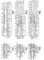
- the mounting support 1 which is shown in the Figs. 1 and 2 consists of an integral, elongate moulded product made of, for example, the thermoplastic material acrylonitrile-butadiene-styrene.
- a plate-shaped member 3 In a first plane (the plane of the drawing in Fig. 1) there is arranged a plate-shaped member 3.
- the plate-shaped member 3 may be an orna- mentel plate, a cover plate, a wall element etc.
- the plate-shaped member consists of a printed-circuit board.
- the board 3 is secured to the mounting support 1 by fastening means to be described hereinafter.
- a second plane perpendicular to the plane of the drawing in Figs.
- a plate-shaped member 5 which consists of a printed-circuit board.
- the borad 3 is secured to the mounting support 1 by fastening means to be described hereinafter.
- the boards 3 and 5 serve as carriers for electronic components which have been omitted for the sake of simplicity.
- the mounting support 1 comprises a first U-section channel having two parallel side walls 7 and 9 and a bottom wall 11. Parallel-to the side wall 7 there extends a further side wall 13 which is connected to the side wall 7 by a bottom wall 15 which extends transversely of the side wall 7. The bottom wall 15 extends parallel to the bottom wall 11.
- the side wall 7 comprises at least one ramp-shaped protrusion 17 on its outer side, which protrusion engages one side of the board 3 at one edge of the board.
- the board 3 is located between the protrusion 17 and the side wall 13, which forms a supporting means for the board 3. When the board 3 is held in a clamped manner between the protrusion 17 and the side wall 13, the board 3 may be disposed in a suspended position.
- the board 3 can be secured at two opposite edges.
- the board 3 can be mounted in the two supports 1 by sliding the board in the longitudinal direction of the supports between the protrusion 17 and the side wall 13 of each support.
- the board 3 can be engaged behind the protrusions 17 by making the board perpendicularlay to its own plane in a direction perpendicular to the bottom walls 11 and 15. During this movement the side walls 7 are deflected towards the associated side walls 9 by cooperation between the edges of the board 3 and the ramp surfaces of the protrusions 17, so that the board 3 can pass over the protrusions 17.
- the side walls 7 subsequently snap back to their original positions and the board 3 is retained between the protrusions 17 and the side walls 13.
- the mounting support 1 may comprise a series of uniformly spaced protrusions 17, so that comparatively large boards 3 or several boards 3 can be mounted. Moreover, boards can then be displaced in the longitudinal direction of the mounting support.
- uniformly-spaced transverse webs 19 are formed between the side walls 7 and 13.
- the side wall 9 comprises at least one ramp-shaped protrusion 21 on its inner side, which protrusion engages the board 5 in a recess 21 in this board.
- the board 5 is mounted by insertion into the first U-section claimed in a direction perpendicular to the bottom wall 11.
- the thickness of the board 5 may be larger than that of the board 3.
- the length of the board 5 (viewed in the longitudinal direction of the mounting support 1) is limited by transverse webs 25 formed between the side walls 7 and 9, which webs serve to reinforce the mounting support 1.
- transverse webs 25 there may be provided holes 27 to receive screws for securing the mounting support 1 against a wall.
- the mounting support 1 may be provided with a series of uniformly spaced protrusions 21 and Transverse webs 25.
- Figs. 3 and 4 show another embodiment of a mounting support.
- the reference numerals in Figs. 3 and 4 correspond to those used in Figs. 1 and 2 wherever possible.
- the side wall 13, the bottom wall 15 and the protrusions 17 of the embodiment shown in Figs. 3 and 4 are identical to those of the embodiment shown in Figs. 1 and 2.
- the difference between the two embodiments lies in the location of the protrusion 21 which engages the board 5.
- the protrusion 21 is formed on one side of a partition 29 which is situtated halfway between the side walls 7 and 9 and which extends parallel thereto.
- the partition 29 forms a second U-section channel which is situated within the first U-section channel and which has the side wall 9 in common therewith.
- the partition 29 extends from one transverse web 25 to another and comprises end portions 31 whose thickness exceeds that of the intermediate portion 33.
- the bottom wall 11 is provided with an opening 35 opposite the protrusion 21.
- the opening 35 and the comparatively small thickness of the portion 33 of the partition 29 impart the desired local flexibility to the partition 29.
- the portion 33 of the partition 29 can then return to its original position so that the protrusion 21 enters the recess 23 in the board 5. Because the height of the partition 29 is smaller than the height of the side walls 7 and 9, the part of the first U-section channel which is situated above the partition 29 serves as a guide means for the board 5. The insertion of the board is thus facilitated. Moreover, the part of the first U-section channel which is situated above the partition 29 can be used to accommodate electric cables.
- Figs. 5 and 6 show a further embodiment of a mounting support.
- the reference numerals used in Figs. 5 and 6 correspond to those used in Figs. ' 1, 2 and 3, 4, wherever possible.
- the mounting support shown in Figs. 5 and 6 is similar to those shown in Figs. 1 to 4 as far as the side wall 13, the bottom wall 15 and the protrusion 17 are concerned.
- This channel is constructed to be symmetrical at the area of the partition 29 by providing a further ramp-shaped protrusion 37 which is identical to the ramp-shaped protrusion 21.
- a further printed-circuit board 39 can thus be mounted in the support 1.
- the board 39 comprises a recess 41 to receive the protrusion 37.
- the board 39 is shown situated opposite the board 5 in Figs. 5 and 6.
- the mounted board 5 would prevent deflection of the partition 29 towards the side wall 7. Therefore, the boards 5 and 39 actually occupy staggered positions with respect to one another in the longitudinal direction of the mounting support.
- ⁇ hen a board 3 is mounted in the aforesaid first plane between two parallel mounting supports arranged with the protrusions 17 on each support facing the other support, the side walls 7 and 13 are twisted simultaneously with the deflection of these side walls.
- the side wall 7 is twisted most.
- the mounting supports can be supplied in standard lengths which are cut to the desirable length by the user.
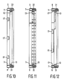
- FIG. 7-12 The further embodiment of a mounting support 1 which is shown in the Figs. 7-12 is shaped as a rectangular frame.
- the frame-shaped mounting support 1 consists essentially of an integral rectangular assembly of mounting supports of the construction shown in Figs. 3 and 6. Therefore, for the sake of clarity and convenience reference numerals corresponding to the reference numerals in Figs. 5 and 6 are used in Fig. 7.
- Four defined areas can be distinguished in the plane of the frame-shaped support 1 (the plane of the drawing), namely, the areas A, B, C and D.
- the areas A, C and D are intended for the mounting of printed-circuit boards with electronic components.
- the area B cannot be occupied when the mounting support is used in a television apparatus, because it serves as a passage for the electron gun.
- the area A is bounded on three sides by mounting supports and on a fourth side (the right-hand side in Fig. 7) by an elongate connecting member 43 which has a transverse cross-section (see Fig. 9)closely resembling that of the previously mentioned L-shaped portion (13, 15) of the transverse cross-section of the mounting supports.
- the area C is bounded in a similar manner to the area A, the boundary on the fourth side being formed by an elongate connecting member 45 which is similar to the connecting member 43 but which also comprises ramp-shaped protrusions 17 (see also Fig. 9).
- the area D is bounded by the connecting members 43 and 45 and by a further connecting member 47 which comprises a ramp-shaped protrusion 17 (see also the Figs. 8 and 9).
- the area B is bounded on one side by part of the frame and on the remaining three sides by the connecting members l t3, 45 and 47.
- the relevant printed-circuit boards are mounted in the areas A, C and D by pressing the boards past the ramprshaped protrusions 17 in a direction perpendicular to the plane of the frame-shaped mounting support (i.e. the plane of the drawing in Fig. 7).
- the side walls 7 and 13 are twisted during this operation. In practice it often occurs that additional printed-circuit boards with electronic components have to be added.
- the first U-section channel which extends along the circumference of the frame-shaped mounting support, allows for the addition of many extra functions to an apparatus by the mounting of boards with electronic components in a second plane and a third plane which extend perpendicularly to the plane of the areas A, B, C and D. Additions of this kind require a comparatively small amount of space in the lateral direction (in the plane of the drawing in Fig. 7), because the fastening means for the additional boards are integrated in the first U-shaped trough.
- the bar-shaped as well as the frame-shaped embodiments of the mounting supports according to the invention offer numerous possibilities for the mounting of boards with electronic components in a variety of electronic apparatuses.
- the supports moreover, can also be used for the formation of walls, ceilings, partitions etc., by the mounting of a variety of plates or boards. This is because the fastening means of the mounting supports generally are particularly suitable for the mounting of plate-shaped members.
- the materials to be used for the described mounting supports are limited to thermoplastic materials, because the flexibility and the twistability of the supports are of great importance.
Landscapes
- Engineering & Computer Science (AREA)
- Microelectronics & Electronic Packaging (AREA)
- Connection Of Plates (AREA)
- Mounting Of Printed Circuit Boards And The Like (AREA)
- Mirrors, Picture Frames, Photograph Stands, And Related Fastening Devices (AREA)
Applications Claiming Priority (2)
| Application Number | Priority Date | Filing Date | Title |
|---|---|---|---|
| NL8104564A NL8104564A (nl) | 1981-10-07 | 1981-10-07 | Montageprofiel voor plaatvormige organen. |
| NL8104564 | 1981-10-07 |
Publications (1)
| Publication Number | Publication Date |
|---|---|
| EP0077092A1 true EP0077092A1 (de) | 1983-04-20 |
Family
ID=19838182
Family Applications (1)
| Application Number | Title | Priority Date | Filing Date |
|---|---|---|---|
| EP82201223A Withdrawn EP0077092A1 (de) | 1981-10-07 | 1982-09-30 | Befestigungsträger für plattenförmige Teile |
Country Status (6)
| Country | Link |
|---|---|
| EP (1) | EP0077092A1 (de) |
| JP (1) | JPS5874908A (de) |
| KR (1) | KR840002393A (de) |
| AR (1) | AR229707A1 (de) |
| BR (1) | BR8205810A (de) |
| NL (1) | NL8104564A (de) |
Cited By (6)
| Publication number | Priority date | Publication date | Assignee | Title |
|---|---|---|---|---|
| FR2678800A1 (fr) * | 1991-07-03 | 1993-01-08 | Avs Sa | Dispositif d'integration de cartes electroniques dans un tiroir ou portes-cartes et module mecanique. |
| FR2693340A1 (fr) * | 1992-07-03 | 1994-01-07 | Jaeger | Ensemble électrique comprenant au moins deux circuits imprimés. |
| US5297009A (en) * | 1991-06-25 | 1994-03-22 | Audio Visuel Systemes | Device for locking in a rack a drawer for electronic board(s) |
| US9175703B2 (en) | 2008-12-17 | 2015-11-03 | Unilin, Bvba | Composed element, multi-layered board and panel-shaped element for forming this composed element |
| US9719542B2 (en) | 2010-06-03 | 2017-08-01 | Unilin, Bvba | Composed element and corner connection applied herewith |
| US10293512B2 (en) | 2011-06-29 | 2019-05-21 | Unilin Bvba | Drawer, drawer construction and method for manufacturing a drawer |
Families Citing this family (1)
| Publication number | Priority date | Publication date | Assignee | Title |
|---|---|---|---|---|
| KR20010044390A (ko) * | 2001-02-16 | 2001-06-05 | 김경식 | 포토벨라 버섯의 재배 방법 |
Citations (4)
| Publication number | Priority date | Publication date | Assignee | Title |
|---|---|---|---|---|
| FR1016352A (fr) * | 1950-04-15 | 1952-11-10 | Perfectionnement à la fabrication des objets rigides en plaques minces | |
| DE1298440B (de) * | 1965-07-30 | 1969-06-26 | Holzwerte Ag | Zerlegbare Kiste |
| DE1935283A1 (de) * | 1969-07-11 | 1971-01-14 | Alfred Schmidt | Kombinationsmoebel |
| DE2008785A1 (de) * | 1970-02-25 | 1971-09-09 | Xaver Frede Moebelfabrik | Steckprofil zur Verbindung von Teilen |
-
1981
- 1981-10-07 NL NL8104564A patent/NL8104564A/nl not_active Application Discontinuation
-
1982
- 1982-09-30 EP EP82201223A patent/EP0077092A1/de not_active Withdrawn
- 1982-10-04 BR BR8205810A patent/BR8205810A/pt unknown
- 1982-10-05 JP JP57174117A patent/JPS5874908A/ja active Pending
- 1982-10-06 KR KR1019820004496A patent/KR840002393A/ko not_active Withdrawn
- 1982-10-07 AR AR290905A patent/AR229707A1/es active
Patent Citations (4)
| Publication number | Priority date | Publication date | Assignee | Title |
|---|---|---|---|---|
| FR1016352A (fr) * | 1950-04-15 | 1952-11-10 | Perfectionnement à la fabrication des objets rigides en plaques minces | |
| DE1298440B (de) * | 1965-07-30 | 1969-06-26 | Holzwerte Ag | Zerlegbare Kiste |
| DE1935283A1 (de) * | 1969-07-11 | 1971-01-14 | Alfred Schmidt | Kombinationsmoebel |
| DE2008785A1 (de) * | 1970-02-25 | 1971-09-09 | Xaver Frede Moebelfabrik | Steckprofil zur Verbindung von Teilen |
Cited By (19)
| Publication number | Priority date | Publication date | Assignee | Title |
|---|---|---|---|---|
| US5297009A (en) * | 1991-06-25 | 1994-03-22 | Audio Visuel Systemes | Device for locking in a rack a drawer for electronic board(s) |
| FR2678800A1 (fr) * | 1991-07-03 | 1993-01-08 | Avs Sa | Dispositif d'integration de cartes electroniques dans un tiroir ou portes-cartes et module mecanique. |
| FR2693340A1 (fr) * | 1992-07-03 | 1994-01-07 | Jaeger | Ensemble électrique comprenant au moins deux circuits imprimés. |
| US12123441B2 (en) | 2008-12-17 | 2024-10-22 | Unilin Bv | Composed element, multi-layered board and panel-shaped element for forming this composed element |
| US9347470B2 (en) | 2008-12-17 | 2016-05-24 | Unilin, Bvba | Composed element, multi-layered board and panel-shaped element for forming this composed element |
| US9695856B2 (en) | 2008-12-17 | 2017-07-04 | Unilin, Bvba | Composed element, multi-layered board and panel-shaped element for forming this composed element |
| US11319977B2 (en) | 2008-12-17 | 2022-05-03 | Flooring Industries Limited, Sarl | Composed element, multi-layered board and panel-shaped element for forming this composed element |
| US9797427B2 (en) | 2008-12-17 | 2017-10-24 | Unilin, Bvba | Composed element, multi-layered board and panel-shaped element for forming this composed element |
| US11788568B2 (en) | 2008-12-17 | 2023-10-17 | Flooring Industries Limited Sarl | Composed element, multi-layered board and panel-shaped element for forming this composed element |
| US10323670B2 (en) | 2008-12-17 | 2019-06-18 | Unilin, Bvba | Composed element, multi-layered board and panel-shaped element for forming this composed element |
| US10731689B2 (en) | 2008-12-17 | 2020-08-04 | Unilin, Bvba | Composed element, multi-layered board and panel-shaped element for forming this composed element |
| US10935063B2 (en) | 2008-12-17 | 2021-03-02 | Unilin Bv | Composed element, multi-layered board and panel-shaped element for forming this composed element |
| US9175703B2 (en) | 2008-12-17 | 2015-11-03 | Unilin, Bvba | Composed element, multi-layered board and panel-shaped element for forming this composed element |
| US11085475B2 (en) | 2008-12-17 | 2021-08-10 | Flooring Industries Limited, Sarl | Composed element, multi-layered board and panel-shaped element for forming this composed element |
| US10982700B2 (en) | 2010-06-03 | 2021-04-20 | Unilin Bv | Composed element and corner connection applied herewith |
| US12000418B2 (en) | 2010-06-03 | 2024-06-04 | Unilin, Bv | Composed element and corner connection applied herewith |
| US9719542B2 (en) | 2010-06-03 | 2017-08-01 | Unilin, Bvba | Composed element and corner connection applied herewith |
| US12607216B2 (en) | 2010-06-03 | 2026-04-21 | Unilin, Bv | Composed element and corner connection applied herewith |
| US10293512B2 (en) | 2011-06-29 | 2019-05-21 | Unilin Bvba | Drawer, drawer construction and method for manufacturing a drawer |
Also Published As
| Publication number | Publication date |
|---|---|
| AR229707A1 (es) | 1983-10-31 |
| BR8205810A (pt) | 1983-09-06 |
| JPS5874908A (ja) | 1983-05-06 |
| NL8104564A (nl) | 1983-05-02 |
| KR840002393A (ko) | 1984-06-25 |
Similar Documents
| Publication | Publication Date | Title |
|---|---|---|
| US3950057A (en) | Composite printed circuit card guide and holding device | |
| US5129842A (en) | Modular patch panel | |
| US7458859B2 (en) | Vertical cable manager | |
| US5576513A (en) | HF-tight component carrier | |
| US5037327A (en) | Connector with means for securing to a substrate | |
| KR880000368B1 (ko) | 통신장치 설치를 위한 래크구조 | |
| US3265935A (en) | Modular chassis | |
| US4699341A (en) | System for mounting radio equipment in vehicles | |
| US8363996B2 (en) | Mounting system for telecommunications panels | |
| GB2111314A (en) | Rack for electronic components | |
| US5934915A (en) | Grounding and screening device | |
| EP0070615A2 (de) | Aufnahmeeinleiten für Leiterplattenbaugruppen | |
| EP0077092A1 (de) | Befestigungsträger für plattenförmige Teile | |
| US4309856A (en) | Panel mounting device and assembly | |
| CA2271152A1 (en) | Sub-rack for circuit boards with central cross-tracks | |
| JP2003523705A (ja) | 配電盤キャビネット | |
| CN101185218B (zh) | 电气设备和用于所述电气设备的壁安装的支撑框架 | |
| US3664510A (en) | Card cage for printed circuit cards | |
| US4486816A (en) | Housing for receiving and storing printed circuit boards | |
| EP0695118A2 (de) | Hochfrequenz-Interferenzen-Dichtungsring | |
| US4278315A (en) | System for interconnection of multiple insulated wires | |
| US5552965A (en) | Control apparatus having a compact and accessible arrangement of printed circuit boards | |
| FI84950B (fi) | Ledningskanal och apparatdosa foer ett ledningskanalsystem. | |
| US3731157A (en) | Printed wiring card guide shelf and a method for manufacture thereof | |
| US5170894A (en) | Insulating strip for a component carrier |
Legal Events
| Date | Code | Title | Description |
|---|---|---|---|
| PUAI | Public reference made under article 153(3) epc to a published international application that has entered the european phase |
Free format text: ORIGINAL CODE: 0009012 |
|
| 17P | Request for examination filed |
Effective date: 19820930 |
|
| AK | Designated contracting states |
Designated state(s): DE FR GB IT NL |
|
| STAA | Information on the status of an ep patent application or granted ep patent |
Free format text: STATUS: THE APPLICATION HAS BEEN WITHDRAWN |
|
| 18W | Application withdrawn |
Withdrawal date: 19850509 |
|
| RIN1 | Information on inventor provided before grant (corrected) |
Inventor name: TILLEMANS, JACOBUS HENDRIKUS |