EP0077146A1 - Security system - Google Patents
Security system Download PDFInfo
- Publication number
- EP0077146A1 EP0077146A1 EP82305115A EP82305115A EP0077146A1 EP 0077146 A1 EP0077146 A1 EP 0077146A1 EP 82305115 A EP82305115 A EP 82305115A EP 82305115 A EP82305115 A EP 82305115A EP 0077146 A1 EP0077146 A1 EP 0077146A1
- Authority
- EP
- European Patent Office
- Prior art keywords
- fibre optic
- elements
- panels
- wall
- panel
- Prior art date
- Legal status (The legal status is an assumption and is not a legal conclusion. Google has not performed a legal analysis and makes no representation as to the accuracy of the status listed.)
- Withdrawn
Links
Images


Classifications
-
- G—PHYSICS
- G08—SIGNALLING
- G08B—SIGNALLING SYSTEMS, e.g. PERSONAL CALLING SYSTEMS; ORDER TELEGRAPHS; ALARM SYSTEMS
- G08B13/00—Burglar, theft or intruder alarms
- G08B13/02—Mechanical actuation
- G08B13/12—Mechanical actuation by the breaking or disturbance of stretched cords or wires
- G08B13/126—Mechanical actuation by the breaking or disturbance of stretched cords or wires for a housing, e.g. a box, a safe, or a room
Definitions
- the invention relates to a security system employing optical fibres for detecting intrusion attempts into a protected area, to a composite panel to be used in the security system and to a method of making the composite panel.
- U.K. Patent Application No. 2,060,966A describes a security system in which a security wall is built up from a number of composite panels incorporating fibre optic elements in hollow tubes. Several panels are stacked together and mounted between a pair of box posts to define a section of the wall. The fibre optic elements in a panel in one section of the wall are connected via connectors in the box posts to fibre optic elements in a panel in an adjacent section of the wall.
- an intruder may also attempt to gain access by releasing a panel from the box posts and from its adjacent panel or panels in the same section of the wall, the fibre optic elements within the panel still having their ends connected to the connectors in the box posts. Then in view of the long lengths of fibre optic elements within the hollow tubes those lengths of fibre optic elements may be sufficiently extensible to allow sufficient rotation of that individual panel so as to gain access through the wall.
- One of the objects of the present invention is to strive to overcome the above problems by constructing the security wall from a number of specially designed composite panels.
- a composite panel comprising at least two fibre optic elements contained within a block of material, the elements bein arranged with portions emerging frcm the panel at three or more spaced locations whose relative positions are such that when a plurality of such panels are installed together to form a security wall or housing having a number of transmission lines within the wall or housing, the panels cannot be moved relative to one another by -translatory movement, rotation or tilting so as to provide access through the security wall or housing without also causing translatory movement of at least one emergent portion of one of the elements, and means being provided to ensure interruption of a transmission line in the wall or housing as a consequence of the translatory movement of the-emergent portion of the element.
- the fibre optic elements within the block of material have their ends emerging from the panel at the three or more spaced locations, the ends of the fibre optic elements in one panel being connectible to respective ends of fibre optic elements in another panel so as to form the security wall or housing having transmission lines therethrough, the elements being firmly embedded within the block of material so that the translatory movement of an end of one of the elements leads to rupture of the element and the interruption of one of the transmission lines through the wall or housing.
- the block of material is conveniently in the form of a polyhedron having at least four faces, and in one embodiment each end of one fibre optic element emerges from the block at a respective one of a pair of faces or corner regions of the block, and one or both ends of a second fibre optic clement emerges from the block at another face or corner region or a respective one of another pair of faces or corner regions of the block.
- the block of material has six faces.
- At least one of the fibre optic elements follows a.circuitous or zig-zag route through the block of material.
- each of the fibre optic elements is carried on a respective supporting member embedded within the block of material, each of two supporting members following a different circuitous or zig-zag route through the block of material.
- each end of one fibre optic element emerges from the block at a respective one of a pair of faces or corner regions of the block
- each end of a second fibre optic element emerges from the block- at a respective one of another pair of faces or corner regions of the block
- the faces or corner regions of each pair may be disposed either adjacent or opposite to one another but preferably they are disposed opposite to one another.
- the ends of the fibre optic elements emerge at small recesses formed in the faces or at the corner regions of the block.
- the composite panels are conveniently manufactured by means of a moulding process using glass fibre reinforced cement or plastics for the block material.
- the fibre. optic elements are laid in the mould in a fixed position, preferably in a zig-zag configuration, and means are provided to retain them in that position whilst the glass fibre reinforced cement or plastics material is poured, sprayed or otherwise introduced into the mould. The material is then allowed to set and the formed composite block removed from the mould.
- the means for retaining the fibre optic elements in a fixed position in the mould is preferably by the provision of supporting members, each fibre optic element being carried on a respective supporting member.
- the supporting member for the fibre optic element may conveniently comprise an elongate carrier strip - formed with a groove along the centre of one side for receiving the fibre optic element, the fibre optic element being held within the groove by an elongate protective strip overlying the fibre and the groove.
- the protective strip is impermeable to fluids which can attack the fibre optic element and conveniently is also flexible so that the pressure of fluids acting on the outside of the protective strip deforms the protective strip into the groove so holding the fibre optic element firmly in place between the protective strip and the carrier strip. Holding the fibre optic elements firmly in place between the protective strip and the carrier strip provides enhanced security as there are no loose portions of the fibre optic elements within the body of the composite panel that can be stretched.
- the protective strip also protects the fibre optic element from contact with particulate material in the block and smooths out the pressure forces exerted on the element by adjacent particulate material.
- the width of the carrier strip substantially larger than its thickness, the ratio of the width of the carrier strip to its thickness, hereinafter referred to as the aspect ratio of the carrier strip, being advantageously more than 10 and in a preferred embodiment more than 20.
- the fibre optic element As the fibre optic element is firmly clamped to the carrier strip so the fibre optic element will bend at the point of the kink with a radius of curvature less than the minimum bend radius allowable if the fibre optic element is to remain intact. Any attempt to penetrate the composite panel which leads to fracture of the panel thereby leads to rupture of a fibre optic element and the generation of an alarm signal.
- the block material and the design of the composite panel is chosen for the particular security application for which the panel is to be employed.
- the composite panels may for example be formed as a completely solid block or have one or more holes through their body enabling fluids or ducting to pass through the panel.
- a wall made from a number of the composite panels being arranged in juxtaposition, each fibre optic element in a panel being connected to a respective fibre optic element in an adjacent panel so as to form a continuous fibre optic line through the wall or housing.
- a security structure consisting of a number of juxtaposed panels having their fibre optic elements connected to respective fibre optic elements in adjacent panels, the panels being arranged so as to partially or completely surround a location to'be protected.
- a feature of the present invention is the provision of a security system in which at least one composite panel is provided to cover an area to be protected, the or each composite panel comprising a block of material having firmly embedded therein at least two fibre optic elements, the elements being arranged with their ends emerging from the panel at three or more-spaced locations whose relative positions are such that they do not all lie along one straight line, means being provided for directing optical radiation along the fibre optic elements and detector means to detect optical radiation that has passed through.the fibre optic elements, the detector means being responsive to a change in detected radiation.
- each composite panel of the security system comprises a block of material in the form of a polyhedron having at least four faces, and embedded in the block are at least two fibre optic elements each of which is carried on a respective supporting member, each end of one fibre optic element emerging from the block at a respective one of a pair of faces or corner regions of the block and one or both of the ends of a second fibre optic element emerging from the block at another face or corner region or a respective one of another pair of faces or corner regions of the block.
- the security system can comprise a number of composite panels in juxtaposition so as to cover a larger area or can be arranged in the form of a security structure partially or completely surrounding a location to be protected.
- each end of the fibre optic elements emerging from one panel is interconnected with a respective end of a fibre optic element emerging from an adjacent juxtaposed panel.
- the fibre optic elements are assembled together in the form of a mesh-like structure, the structure having a number of jointing points at which portions of the elements are secured by securing means in a position fixed relative to one another, the portion of an element emerging from the block being sufficiently close to a jointing point to ensure that translatory movement of the emergent portion leads to rupture of the element and the interruption of one of the transmission lines through the wall or housing.
- each panel is formed from two interconnectable sections which are manufactured by a moulding process using glass fibre reinforced cement or plastics material.
- Each or both of the sections may be provided with a mesh-like groove into which the mesh-like structure can be located.
- the mesh in the composite panels may be firmly or loosely held in place between the sections of the-panels.
- the mesh used is preferably like the mesh-like intruder detection structures described in European Patent Application No. 0049979.
- the present invention provides a security wall or housing made from a number of composite panels arranged in juxtaposition, a mesh-like structure of fibre optic elements extending through the wall or housing to define a number of transmission lines, the mesh-like structure having a number of jointing points at which portions of the elements are secured by securing means in a position fixed relative to one another, the portion of an element extending between two adjacent panels being sufficiently close to a jointing point to ensure that translatory movement of that portion leads to rupture of the element and the interruption of one of the transmission lines through the wall or housing.
- the invention also provides a security system in which the security wall or housing made up from a number of composite panels as described in the preceding paragraph is provided with means for directing optical radiation along the fibre optic elements in the mesh and detector means to detect optical radiation that has passed through the fibre optic elements, the detector means being responsive to a change in detected radiation.
- a composite panel 1 comprises a block 2 of glass fibre reinforced cement in which is embedded two fibre optic elements 4,6 in the form of single optical fibres carried on a respective supporting member 8,10.
- Each of the supporting members 8,10 follow a circuitous route through the block 2 and are arranged so that the ends of each of the fibre optic elements 4,6 emerge from opposite recessed corners of the block 2.
- the supporting member 10 and its fibre optic element 6 is embedded in the block 2 in a different plane to that of the supporting member 8 and its fibre optic element 4, the two differing zig-zag routes of the supporting members 8, 10 together forming a grid-like configuration within the block 2.
- the supporting members 8,10 each comprise an elongate steel carrier strip 12 formed with a groove 13 along the centre of one side for receiving an optical fibre 14, the optical. fibre 14 being enclosed within a plastics sheathing 16.
- the optical fibre 14 and its plastics sheathing 16 are held within the groove 13 by a protective flexible strip 18, the strip 18 being adhesively secured to the carrier strip 12 at each side of the groove 13.
- the optical fibre 14 and the plastics sheathing 16 can both be attacked by the chemical action of the alkaline fluids found in glass fibre reinforced cement. For this reason the strip 18 has at least part of its structure made from a material that acts as an impermeable barrier to those alkaline fluids.
- the strip 18 can be made from any one of a variety of metals or metal alloys, for example aluminium strip or tape.
- the pressures from the alkaline fluids and from any particulate material in the block material in the vicinity of the fibre optic element tend to be smoothed out by the flexible strip 18 so that a fairly equal pressure P is exerted along the length of the fibre optic element 14.
- the carrier strip 12 has an aspect ratio, that is the ratio of its width W to its thickness T, of greater than 20.
- Figure 3 illustrates how four composite panels 22, 24, 26 and 28, all of which are like that shown in figure 1, can be arranged together in juxtaposition.
- the recessed corners of the panels 22, 24, 26 and 28 together define a cavity 30 in which the ends of the fibre optic elements 23, 25, 27 and 29 are connected together in pairs by a connector 32.
- the end of fibre optic element 23 is connected to the end of the fibre optic element 29 whilst the end of fibre optic element 27 is connected to the end of fibre optic element 25.
- the fibre optic elements 23 and 29 in composite panels 22 and 28 together form a single fibre optic transmission line whilst the fibre optic elements 25 and 27 in composite panels 24 and 26 form another single fibre optic transmission line.
- An alternative embodiment is for the ends of the fibre optic elements in each composite panel to emerge at the mid-point of the side faces of the panels, the mid-points of the side faces being formed with or without a recess.
- the mid-points of the side faces of the composite panels are represented by letters A, B, C and D.
- figure 6 shows how twenty four composite panels, each like that of figure 1, can be assembled together to form a cubic housing whose interior represents the protected area in which there could be for example a safe, bank vault, nuclear explosive store, building reactor, or the interior may simply represent a room.
- the housing has a roof 40, a floor and four side walls, only two of which are shown and designated by numerals 42 and 44 for ease of illustration.
- the corners of the adjoining panels define the cavities 30 at which the - ends of the fibre optic elements are joined together, the dotted lines being representative for illustrative purposes of the typical continuous fibre optic transmission lines that can be formed around the housing.
- One transmission line is formed by the joining together of a fibre optic element in each of the composite panels 46, 47 and 48 and so on in other panels around the cubic housing returning so as to join up again with the fibre optic element in the composite panel 46.
- a fibre optic transmission loop is created around the cubic housing.
- Parts of two other transmission loops are illustrated by the dotted lines passing through composite panels 50, 52, 54 and 56 and through composite panels 58, 60.
- the transmittors and receivers are housed for illustrative purposes in a box 70 and are connected by transmission lines 72, 74 and 76 to terminals in cavities 30 of respective loop transmission lines around the cubic housing.
- the security structures made up by the composite panels of figure 1 are such that the optic fibre elements are interconnected with optic fibre elements of adjacent - panels at the corners. A potential intruder cannot remove, rotate or tilt any panel without breaking an interconnection at a corner of the panel and so creating an alarm signal.
- a security system comprising a number of composite panels as described above is that they can be prefabricated in the factory and installed rapidly around the area to be protected.
- the composite panels may for example be bolted together and arranged around the area to be protected.
- they may be bolted onto the existing wall or walls or à room or security housing. They could for example be arranged on the inner or outer walls of a bank vault.
- composite panels described above are in the form of completely solid blocks many other panel designs can be adopted.
- the composite panel or panels can be formed during the moulding process with one or more holes. The water from the outflow pipe can then pass through the holes.
- the composite panel is in the form of a grid having a number of openings 62 defined between a mesh of composite bars 64.
- the supporting members and. their fibre optic elements are embedded within and pass along the bars 64 in a circuitous route through the ends of each of the fibre optic elements 4, 6 emerging from opposite recessed corners of the block 2.
- a composite panel 80 consists of two half sections, the cross-section through one of which is shown in figure 9, together sandwiching between them a mesh of fibre optic elements four of which are shown designated 82, 83, 84 and 85. Only a part of the mesh is shown in figure 8 and in practice the mesh extends throughout the whole length and width of the panel.
- the mesh can be in any of the forms described in European Application No. 0049979.
- the elements 82, 83, 84 and 85 are in the form of optical fibres surrounded by or coated with polyvinylchloride and portions of pairs of the elements 82, 83, 84 and 85 meet at a number of jointing points 86 where they are encapsulated in plastics material.
- the plastics material secures the portions of the elements at the jointing points 86 in positions fixed relative to one another and adjacent jointing points 86 are spaced apart at distances of 20 cms or less.
- Portions of the fibre optic elements 82, 83, 84 and 85 are shown emerging from one side wall 81 of the panel 80 and the emergent portions have been designated 87, 88, 89 and 90 respectively.
- the element 82 emerges from the panel in small loops at a number of spaced locations along the length of the panel. Only three of these locations are shown in figure 8 and have been designated by numerals 92, 93 and 94.
- numerals 92, 93 and 94 At the bottom 99 of the panel small loops of elements also emerge at a number of spaced locations.
- Figure 9 is a section through one half section 96 of the panel 80 of figure 8. Another half section (not shown) identical to half section 96 is also provided. Both are formed with grooves 98 which are arranged in a mesh-like configuration to house the mesh of fibre optic elements. The half sections are bolted together to form the complete panel 80.
- Figure 10 illustrates a number of composite panels 111, 112, 113, 114, 115 and 116 assembled to form a security wall 100. Only part of the security wall 100 is shown for simplicity of drawing and it extends across a river the bed of which is illustrated by line 102.
- the posts 106 are first erected in their concrete foundations 104. Half sections of the panels 114, 115 and 116 are then bolted into place between the posts 106. A continuous length of mesh of fibre optic elements like that shown in figure 8 is then located in the grooves of the half sections and when in place the remaining half sections of panels 114, 115 and 116 are bolted into place.
- the composite panels 111, 112 and 113 are similarly assembled with a continuous length of mesh extending through the interior of the panels.
- the ends of the fibre optic elements which form the mesh emerge at the post 106 shown on the far left of figure 10.
- the elements are attached to fixed connectors which link the elements to other fibre optic elements which are routed through a cable 118 to an electronics unit 120 located in a dry area.
- the end portions of the fibre optic elements emerging from panels 111 and 114 and attached to respective connectors in post 106 are of short lengths and each extends in this embodiment less than 20 cms from the nearest jointing point 86.
- the continuous lengths of elements emerging from and extending between adjacent pairs of panels, such as panels 111, 112 or panels 112, 113 or panels 114, 115 or panels 115, 116 are also of short lengths, less than 20 cms, from the nearest jointing points 86. If any attempt is made to move adjacent panels relative to one another to a degree so as to provide access through the wall 100 some of the emerging portions are subjected to translatory movement. As the length of emergent portion is short and near a jointing point 86 any extensibility in the length of the emergent portion is quickly taken up and rupture of a fibre optic element occurs.
- a number of means are available to increase security even further so as to ensure that. relative movement between adjacent panels 111, 114 or panels 112, 115 or panels 113, 116 will also cause rupture of fibre optic elements.
- One convenient method is to employ just one large mesh of fibre optic elements whose continuous length extends through all of the panels in the security wall 100. Thus emergent portions of the elements would then also interconnect the panels 111 and 114, 112 and 115, 113 and 116.
- the loops are only small relative movement between for example panels 111 and 114 causes translatory movement of the elements in the loops which due to the proximity of jointing points 86 close to the loops results in rupture of one or more of the elements.
- the size and geometry of the panels, the spacing of the locations at which the fibre optic elements emerge, and the lengths of the emerging ends or portions of the fibre optic elements are chosen to suit the requirements of the security system in which the panels are employed so that any movement of a panel sufficient to defeat the the particular security required from the system is also sufficient to cause such interruption in a fibre optic transmission line.
Landscapes
- Physics & Mathematics (AREA)
- General Physics & Mathematics (AREA)
- Panels For Use In Building Construction (AREA)
- Finishing Walls (AREA)
- Burglar Alarm Systems (AREA)
Abstract
A composite security panel (2) having at least two fibre optic elements (4, 6) contained within a block (2) of material, the elements (4, 6) being arranged with portions emerging from the panel at three or more spaced locations. Translatory movement, rotation or tilting of the panel (2) when assembled in a wall or housing causing translatory movement of an emergent portion of an element resulting in the interruption of a transmission line through the wall or housing. The elements (4, 6) may be firmly embedded within the panels, the fibre optic (14) being carried on a strip of material (12), or the elements (82, 83, 84) may be formed into a mesh which can be loosely housed between interconnectable sections of the panels.
Description
- The invention relates to a security system employing optical fibres for detecting intrusion attempts into a protected area, to a composite panel to be used in the security system and to a method of making the composite panel.
- A number of security systems which make use of fibre optic elements in their construction are known. In South African Patent No. 78/5419 for example a security system is described in which fibre optic elements are located in a wall along a boundary of an area to be protected. Breakage or damage to one or more of the fibre optic elements, caused for example by an intruder, results in a reduction in the intensity of or complete loss of an optical signal in such fibre optic elements and the detection of this signal intensity reduction or loss
- signifies an intrusion attempt. In the specification accompanying U.K. Patent Application GB 2,038,060A another security system is disclosed, and in that arrangement a wall to be protected has embedded in it a mesh of optical fibres with the fibres arranged in a reticulated pattern. Each fibre has a light source. at one end and a light detector at the other end. If one or more of the fibres is broken then the cessation of light in such fibres is used to give an alarm.
- The above known security systems tend to be both expensive and difficult to install, one needing to take great care that the fibre optic elements are not damaged during the erection of the wall in which they are being embedded. Furthermore should a fault occur in one or more of the fibre optic elements, either during the erection or subsequent to the erection of the wall, then the location of that fault and its repair may be an expensive and difficult procedure involving the destruction of a part or in extreme cases the whole of the wall. Such walls are also built so that they cannot easily be dismantled without damage to the fibre optic elements embedded within the wall. This can be a disadvantage if one wished to dismantle part of the wall to repair a fault or to dismantle the wall completely so as to re-erect it elsewhere as a major portion of the fiore optic elements may need to be replaced as a result of damage caused to them by the part or total dismantling- of the wall.
- U.K. Patent Application No. 2,060,966A describes a security system in which a security wall is built up from a number of composite panels incorporating fibre optic elements in hollow tubes. Several panels are stacked together and mounted between a pair of box posts to define a section of the wall. The fibre optic elements in a panel in one section of the wall are connected via connectors in the box posts to fibre optic elements in a panel in an adjacent section of the wall. One of the disadvantages of this security system and the other known security systems described above is that they provide only a limited degree of security in that an intruder once having carefully removed part of the wall and gained access to the fibre optic elements may then succeed in gently stretching adjacent fibre optic elements apart so as to create a gap sufficient to squeeze through, without there being any rupture of the optic fibre elements. It is possible to stretch fibre optic elements apart in this way because of the elasticity of the fibres some of which can be extended by up to 3% before they rupture.
- In the security wall described in U.K. Patent Application No. 2,060,966A an intruder may also attempt to gain access by releasing a panel from the box posts and from its adjacent panel or panels in the same section of the wall, the fibre optic elements within the panel still having their ends connected to the connectors in the box posts. Then in view of the long lengths of fibre optic elements within the hollow tubes those lengths of fibre optic elements may be sufficiently extensible to allow sufficient rotation of that individual panel so as to gain access through the wall.
- One of the objects of the present invention is to strive to overcome the above problems by constructing the security wall from a number of specially designed composite panels.
- According to the present invention there is provided a composite panel comprising at least two fibre optic elements contained within a block of material, the elements bein arranged with portions emerging frcm the panel at three or more spaced locations whose relative positions are such that when a plurality of such panels are installed together to form a security wall or housing having a number of transmission lines within the wall or housing, the panels cannot be moved relative to one another by -translatory movement, rotation or tilting so as to provide access through the security wall or housing without also causing translatory movement of at least one emergent portion of one of the elements, and means being provided to ensure interruption of a transmission line in the wall or housing as a consequence of the translatory movement of the-emergent portion of the element.
- In one embodiment the fibre optic elements within the block of material have their ends emerging from the panel at the three or more spaced locations, the ends of the fibre optic elements in one panel being connectible to respective ends of fibre optic elements in another panel so as to form the security wall or housing having transmission lines therethrough, the elements being firmly embedded within the block of material so that the translatory movement of an end of one of the elements leads to rupture of the element and the interruption of one of the transmission lines through the wall or housing. The block of material is conveniently in the form of a polyhedron having at least four faces, and in one embodiment each end of one fibre optic element emerges from the block at a respective one of a pair of faces or corner regions of the block, and one or both ends of a second fibre optic clement emerges from the block at another face or corner region or a respective one of another pair of faces or corner regions of the block. In a preferred embodiment the block of material has six faces.
- Advantageously at least one of the fibre optic elements follows a.circuitous or zig-zag route through the block of material. In a preferred embodiment each of the fibre optic elements is carried on a respective supporting member embedded within the block of material, each of two supporting members following a different circuitous or zig-zag route through the block of material.
- In embodiments in which each end of one fibre optic element emerges from the block at a respective one of a pair of faces or corner regions of the block, and each end of a second fibre optic element emerges from the block- at a respective one of another pair of faces or corner regions of the block, the faces or corner regions of each pair may be disposed either adjacent or opposite to one another but preferably they are disposed opposite to one another.
- In one embodiment the ends of the fibre optic elements emerge at small recesses formed in the faces or at the corner regions of the block.
- The composite panels are conveniently manufactured by means of a moulding process using glass fibre reinforced cement or plastics for the block material. In the moulding process the fibre. optic elements are laid in the mould in a fixed position, preferably in a zig-zag configuration, and means are provided to retain them in that position whilst the glass fibre reinforced cement or plastics material is poured, sprayed or otherwise introduced into the mould. The material is then allowed to set and the formed composite block removed from the mould.
- If the fibre optic elements are not retained in a fixed position within the mould during the moulding process then there is a tendency for portions of the fibre optic elements to become distorted and form kinks at points along the elements. This can create high and deleterious stresses at those points along the length of the fibre optic elements and such stresses may lead to the rupture of the fibre optic element at those points.
- The means for retaining the fibre optic elements in a fixed position in the mould is preferably by the provision of supporting members, each fibre optic element being carried on a respective supporting member.
- The supporting member for the fibre optic element may conveniently comprise an elongate carrier strip - formed with a groove along the centre of one side for receiving the fibre optic element, the fibre optic element being held within the groove by an elongate protective strip overlying the fibre and the groove. Preferably the protective strip is impermeable to fluids which can attack the fibre optic element and conveniently is also flexible so that the pressure of fluids acting on the outside of the protective strip deforms the protective strip into the groove so holding the fibre optic element firmly in place between the protective strip and the carrier strip. Holding the fibre optic elements firmly in place between the protective strip and the carrier strip provides enhanced security as there are no loose portions of the fibre optic elements within the body of the composite panel that can be stretched. The protective strip also protects the fibre optic element from contact with particulate material in the block and smooths out the pressure forces exerted on the element by adjacent particulate material.
- It is advantageous to provide barbs or serrations along the edge or edges of the carrier strip as they assist in keying the carrier strip in the material of the block. I is also advantageous to make the width of the carrier strip substantially larger than its thickness, the ratio of the width of the carrier strip to its thickness, hereinafter referred to as the aspect ratio of the carrier strip, being advantageously more than 10 and in a preferred embodiment more than 20. By choosing a sufficiently high aspect ratio for the carrier strips within a composite panel one can ensure that when a force is exerted on the panel such as to fracture the block material, so the carrier strips form kinks at the region of fracture. As the fibre optic element is firmly clamped to the carrier strip so the fibre optic element will bend at the point of the kink with a radius of curvature less than the minimum bend radius allowable if the fibre optic element is to remain intact. Any attempt to penetrate the composite panel which leads to fracture of the panel thereby leads to rupture of a fibre optic element and the generation of an alarm signal.
- The block material and the design of the composite panel is chosen for the particular security application for which the panel is to be employed. The composite panels may for example be formed as a completely solid block or have one or more holes through their body enabling fluids or ducting to pass through the panel.
- In one embodiment there is provided a wall made from a number of the composite panels being arranged in juxtaposition, each fibre optic element in a panel being connected to a respective fibre optic element in an adjacent panel so as to form a continuous fibre optic line through the wall or housing.
- In another embodiment there is provided a security structure consisting of a number of juxtaposed panels having their fibre optic elements connected to respective fibre optic elements in adjacent panels, the panels being arranged so as to partially or completely surround a location to'be protected.
- A feature of the present invention is the provision of a security system in which at least one composite panel is provided to cover an area to be protected, the or each composite panel comprising a block of material having firmly embedded therein at least two fibre optic elements, the elements being arranged with their ends emerging from the panel at three or more-spaced locations whose relative positions are such that they do not all lie along
one straight line, means being provided for directing optical radiation along the fibre optic elements and detector means to detect optical radiation that has passed through.the fibre optic elements, the detector means being responsive to a change in detected radiation. - In one embodiment the or each composite panel of the security system comprises a block of material in the form of a polyhedron having at least four faces, and embedded in the block are at least two fibre optic elements each of which is carried on a respective supporting member, each end of one fibre optic element emerging from the block at a respective one of a pair of faces or corner regions of the block and one or both of the ends of a second fibre optic element emerging from the block at another face or corner region or a respective one of another pair of faces or corner regions of the block.
- The security system can comprise a number of composite panels in juxtaposition so as to cover a larger area or can be arranged in the form of a security structure partially or completely surrounding a location to be protected. In such embodiments each end of the fibre optic elements emerging from one panel is interconnected with a respective end of a fibre optic element emerging from an adjacent juxtaposed panel.
- In another embodiment of composite panel the fibre optic elements are assembled together in the form of a mesh-like structure, the structure having a number of jointing points at which portions of the elements are secured by securing means in a position fixed relative to one another, the portion of an element emerging from the block being sufficiently close to a jointing point to ensure that translatory movement of the emergent portion leads to rupture of the element and the interruption of one of the transmission lines through the wall or housing.
- In such an embodiment it is convenient to assemble the panels in situ with a continuous length of mesh extending through and between them. In one method of assembly each panel is formed from two interconnectable sections which are manufactured by a moulding process using glass fibre reinforced cement or plastics material. Each or both of the sections may be provided with a mesh-like groove into which the mesh-like structure can be located. When building the panels into a wall or housing first sections from each of the panels are mounted together in line so as to define a length of the wall or housing, the continuous length of mesh is then located into the grooves of the assembled-first sections and the remaining second sections of each of the panels are then secured in place over the first sections to enclose the mesh. In this way a number of composite panels are assembled in situ to provide a wall or housing.
- The mesh in the composite panels may be firmly or loosely held in place between the sections of the-panels.
- The mesh used is preferably like the mesh-like intruder detection structures described in European Patent Application No. 0049979.
- In one embodiment the present invention provides a security wall or housing made from a number of composite panels arranged in juxtaposition, a mesh-like structure of fibre optic elements extending through the wall or housing to define a number of transmission lines, the mesh-like structure having a number of jointing points at which portions of the elements are secured by securing means in a position fixed relative to one another, the portion of an element extending between two adjacent panels being sufficiently close to a jointing point to ensure that translatory movement of that portion leads to rupture of the element and the interruption of one of the transmission lines through the wall or housing.
- The invention also provides a security system in which the security wall or housing made up from a number of composite panels as described in the preceding paragraph is provided with means for directing optical radiation along the fibre optic elements in the mesh and detector means to detect optical radiation that has passed through the fibre optic elements, the detector means being responsive to a change in detected radiation.
- The invention will be described further by way of example with reference to and as illustrated in the accompanying drawings in which:-
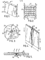
- Figure 1 shows in perspective one embodiment of a composite panel-according to the present invention,
- Figure 2 is a cross-section through the centre of the composite panel of Fig. 1,
- Figure 3 illustrates how four composite panels of Fig. 1 can be assembled together,
- Figure 4 is one embodiment of a supporting member shown in Fig. 2 carrying the lengths of fibre optic element embedded in the composite panel,
- Figure 5 is a section along the line I-I of Fig. 4,
- Figure 6 is a cube shaped security structure built up from composite panels like that of Fig. 1,
- Figure 7 is a further embodiment of a composite panel,
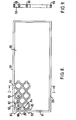
- Figure 8 is a further embodiment of a composite panel,
- Figure 9 is a section along the line II of figure 8 and
- Figure 10 is a security wall assembled from panels of figure 8.
- Referring to figures 1 and 2 a composite panel 1 comprises a
block 2 of glass fibre reinforced cement in which is embedded two fibre optic elements 4,6 in the form of single optical fibres carried on a respective supportingmember 8,10. Each of the supportingmembers 8,10 follow a circuitous route through theblock 2 and are arranged so that the ends of each of the fibre optic elements 4,6 emerge from opposite recessed corners of theblock 2. The supportingmember 10 and its fibre optic element 6 is embedded in theblock 2 in a different plane to that of the supporting member 8 and its fibre optic element 4, the two differing zig-zag routes of the supportingmembers 8, 10 together forming a grid-like configuration within theblock 2. - Referring now to figures 4 and 5 the supporting
members 8,10 each comprise an elongatesteel carrier strip 12 formed with agroove 13 along the centre of one side for receiving anoptical fibre 14, the optical.fibre 14 being enclosed within aplastics sheathing 16. Theoptical fibre 14 and itsplastics sheathing 16 are held within thegroove 13 by a protectiveflexible strip 18, thestrip 18 being adhesively secured to thecarrier strip 12 at each side of thegroove 13. Theoptical fibre 14 and the plastics sheathing 16 can both be attacked by the chemical action of the alkaline fluids found in glass fibre reinforced cement. For this reason thestrip 18 has at least part of its structure made from a material that acts as an impermeable barrier to those alkaline fluids. Thestrip 18 can be made from any one of a variety of metals or metal alloys, for example aluminium strip or tape. The pressures from the alkaline fluids and from any particulate material in the block material in the vicinity of the fibre optic element tend to be smoothed out by theflexible strip 18 so that a fairly equal pressure P is exerted along the length of thefibre optic element 14. - The
carrier strip 12 has an aspect ratio, that is the ratio of its width W to its thickness T, of greater than 20. - Figure 3 illustrates how four
composite panels panels cavity 30 in which the ends of the fibreoptic elements connector 32. The end offibre optic element 23 is connected to the end of thefibre optic element 29 whilst the end offibre optic element 27 is connected to the end offibre optic element 25. In this manner the fibreoptic elements composite panels optic elements composite panels - An alternative embodiment is for the ends of the fibre optic elements in each composite panel to emerge at the mid-point of the side faces of the panels, the mid-points of the side faces being formed with or without a recess. In figure 3 the mid-points of the side faces of the composite panels are represented by letters A, B, C and D. Thus the ends of a pair of fibre optic elements in adjoining
panels panels panels panels - By arranging the composite panels together in juxtaposition like that illustrated in figure 3 it is possible to build up a wall extending along a boundary of an area to be protected. Also one has the facility to build up a security structure partially or completely surrounding a location to be protected. The number and size of the composite panels may vary greatly depending on the size of the area to be protected and on the shape of the security structure required.
- For the purpose of illustration figure 6 shows how twenty four composite panels, each like that of figure 1, can be assembled together to form a cubic housing whose interior represents the protected area in which there could be for example a safe, bank vault, nuclear explosive store, building reactor, or the interior may simply represent a room. The housing has a roof 40, a floor and four side walls, only two of which are shown and designated by
numerals cavities 30 at which the - ends of the fibre optic elements are joined together, the dotted lines being representative for illustrative purposes of the typical continuous fibre optic transmission lines that can be formed around the housing. One transmission line is formed by the joining together of a fibre optic element in each of thecomposite panels composite panel 46. In this way a fibre optic transmission loop is created around the cubic housing. Parts of two other transmission loops are illustrated by the dotted lines passing throughcomposite panels composite panels example face 42. - In figure 6 the transmittors and receivers are housed for illustrative purposes in a
box 70 and are connected bytransmission lines cavities 30 of respective loop transmission lines around the cubic housing. - The security structures made up by the composite panels of figure 1 are such that the optic fibre elements are interconnected with optic fibre elements of adjacent - panels at the corners. A potential intruder cannot remove, rotate or tilt any panel without breaking an interconnection at a corner of the panel and so creating an alarm signal.
- One of the advantages of constructing a security system comprising a number of composite panels as described above is that they can be prefabricated in the factory and installed rapidly around the area to be protected. The composite panels may for example be bolted together and arranged around the area to be protected. Alternatively they may be bolted onto the existing wall or walls or à room or security housing. They could for example be arranged on the inner or outer walls of a bank vault.
- It is to be understood that although the composite panels described above are in the form of completely solid blocks many other panel designs can be adopted. For example, if it is desired to install a composite panel or panels over or around the end of a water outflow pipe leading from a nuclear power station thenthe composite panel or panels can be formed during the moulding process with one or more holes. The water from the outflow pipe can then pass through the holes.
- In one embodiment as shown in figure 7 the composite panel is in the form of a grid having a number of
openings 62 defined between a mesh of composite bars 64. The supporting members and. their fibre optic elements are embedded within and pass along thebars 64 in a circuitous route through the ends of each of the fibre optic elements 4, 6 emerging from opposite recessed corners of theblock 2. - In figure 8 a
composite panel 80 consists of two half sections, the cross-section through one of which is shown in figure 9, together sandwiching between them a mesh of fibre optic elements four of which are shown designated 82, 83, 84 and 85. Only a part of the mesh is shown in figure 8 and in practice the mesh extends throughout the whole length and width of the panel. The mesh can be in any of the forms described in European Application No. 0049979. In a preferred form theelements elements - Portions of the fibre
optic elements side wall 81 of thepanel 80 and the emergent portions have been designated 87, 88, 89 and 90 respectively. At the top 91 of the panel theelement 82 emerges from the panel in small loops at a number of spaced locations along the length of the panel. Only three of these locations are shown in figure 8 and have been designated bynumerals - Figure 9 is a section through one
half section 96 of thepanel 80 of figure 8. Another half section (not shown) identical tohalf section 96 is also provided. Both are formed withgrooves 98 which are arranged in a mesh-like configuration to house the mesh of fibre optic elements. The half sections are bolted together to form thecomplete panel 80. - Figure 10 illustrates a number of
composite panels security wall 100. Only part of thesecurity wall 100 is shown for simplicity of drawing and it extends across a river the bed of which is illustrated byline 102. - At spaced locations within the
river bed 102 are formed a number ofconcrete foundations 104 for supportingconcrete posts 106. Between theposts 106 are mounted thecomposite panels - To assemble the
wall 100 theposts 106 are first erected in theirconcrete foundations 104. Half sections of thepanels posts 106. A continuous length of mesh of fibre optic elements like that shown in figure 8 is then located in the grooves of the half sections and when in place the remaining half sections ofpanels composite panels post 106 shown on the far left of figure 10. The elements are attached to fixed connectors which link the elements to other fibre optic elements which are routed through acable 118 to anelectronics unit 120 located in a dry area. - The end portions of the fibre optic elements emerging from
panels post 106 are of short lengths and each extends in this embodiment less than 20 cms from thenearest jointing point 86. Similarly the continuous lengths of elements emerging from and extending between adjacent pairs of panels, such aspanels panels panels panels wall 100 some of the emerging portions are subjected to translatory movement. As the length of emergent portion is short and near ajointing point 86 any extensibility in the length of the emergent portion is quickly taken up and rupture of a fibre optic element occurs. - A number of means are available to increase security even further so as to ensure that. relative movement between
adjacent panels panels panels security wall 100. Thus emergent portions of the elements would then also interconnect thepanels - Alternatively one can instal a long length of fibre (not shown) through the series of small loops of the elements (see figure 8) emerging at the top of
panels panels example panels - It will be seen that in each of the above described embodiments ends or portions of the fibre optic elements emerge from the panel at spaced locations whose relative positions are such that they do not all lie along a straight line. Translatory movement, rotation or tilting of the panel hence necessarily causes translatory movement of at least one end of at least one of the fibre optic elements. Assuming such movement is large enough, this will cause the fibre optic element to break or otherwise become disconnected from the fibre optic element in the adjacent panel and thereby cause an interruption in the respective fibre optic transmission line. It will be appreciated that the size and geometry of the panels, the spacing of the locations at which the fibre optic elements emerge, and the lengths of the emerging ends or portions of the fibre optic elements are chosen to suit the requirements of the security system in which the panels are employed so that any movement of a panel sufficient to defeat the the particular security required from the system is also sufficient to cause such interruption in a fibre optic transmission line.
Claims (23)
1. A composite panel comprising at least two fibre optic elements (4, 6, 23, 25, 27, 29, 82, 83, 84, 85) contained within a block (2) of material, the elements (4, 6, 23, 25, 27, 29, 82, 83, 84, 85) being arranged with portions (87, 88, 89, 90, 92, 93, 94) emerging from the panel (1, 22, 24, 26, 28, 80) at three or more spaced locations whose relative positions are such that when a plurality of such panels (1, 22, 24, 26, 28, 80) are installed together to form a security wall or housing having a number of transmission lines (72, 74, 76) within the wall or housing, the panels cannot be moved relative to one another by translatory movement, rotation or tilting so as to provide access through the security wall or housing without also causing translatory movement of at least one emergent portion (87, 88, 89, 90, 92, 93, 94) of one of the elements (4, 6, 23, 25, 27, 29, 82, 83, 84, 85) characterised in that means (2, 86) is provided to ensure interruption of a transmission line (72, 74, 76) in a wall or housing as a consequence of the translatory movement of the emergent portion (87, 88, 89, 90, 92, 93, 94) of an element (4, 6, 23, 25, 27, 29, 83, 84, 85).
2. A composite panel as claimed in claim 1 characterised in that the fibre optic elements (4, 6, 23, 25, 27, 29) are firmly embedded within the block (2) of material so that the translatory movement of an end of one of the elements (4, 6, 23, 25, 27, 29) leads to rupture of the element (4, 6, 23, 25, 27, 29) and the interruption of one of the transmission lines (72, 74, 76) through the wall or housing.
3. A composite panel as claimed in claim 2 characterised in that the block (2) of material is in the form of a polyhedron having at least four faces, each end of one fibre optic element (4) emerging from the block (2) at a respective one of a pair of faces or corner regions of the block (2), and one or both ends of a second fibre optic element (6) emerging from the block (2) at another face or corner region or a - respective one of another pair of faces or corner regions of the block (2).
4. A composite panel as claimed in claim 3 characterised in that each end of the second fibre optic element (6) emerges from the block at a respective one of the other pair of faces or corner regions of the block (2), the faces or corner regions of each pair being disposed adjacent or opposite to one another.
5. A composite panel as claimed in any of claims 2 to 4 characterised in that each fibre optic element (4, 6, 23, 25, 27, 29) is carried on a respective supporting member (8, 10) embedded within the block (2) of material.
6. A composite panel as claimed in any of claims 2 to 5 characterised in that at least one of the fibre optic elements (4, 6) follows a circuitous route through the block (2) of material.
7. A composite panel as claimed in any of claims 2 to 6 characterised in that the ends of the elements (4, 6, 23, 25, 27, 29) emerge at recesses formed in the faces or at the corner regions of the block.
8. A composite panel as claimed in claim 5, or claims 6 or 7, when dependent on claim 5, characterised in that the supporting member (12) for the elements (4, 6, 23, 25, 27, 29) comprises an elongate carrier strip (12) formed with a groove (13) along the centre of one side for receiving a fibre optic element (14), the fibre optic element (14) being held within the groove (13) by an elongate protective strip (18) overlying the element (14) and the groove (13).
9. A composite panel as claimed in claim 8 characterised in that the protective strip (18) is impermeable to fluids which can attack the fibre optic element (14).
10. A composite panel as claimed in claim 8 or 9 characterised in that barbs or serrations are provided along the edge or edges of the carrier strip (12).
11. A composite panel as claimed in any of claims 8 to 10 characterised in that the ratio of the width of the carrier strip (12) to its thickness is more than 10.
12. A composite panel as claimed in claim 11 characterised in that the ratio of the width of the carrier strip (12) to its thickness is more than 20.
13. A wall characterised in that it is constructed from a number of composite panels (22, 24, 26, 28) as claimed in any of claims 1 to 12, the composite panels (22, 24, 26, 28) being arranged in juxtaposition, each fibre optic element (23, 25, 27, 29) in a panel (22, 24, 26, 28) being connected to a respective fibre optic element (29, 27, 25, 23) in an adjacent panel (28, 26, 24, 22).
14. A security structure in the form of a housing characterised in that it is constructed from a nunber of composite panels (46, 47, 48, 50, 52, 54, 56, 58, 60) as claimed in any of claims 1 to 12, the panels (46, 47, 48, 50, 52, 54, 56, 58, 60) having their fibre optic elements connected to respective fibre optic elements in adjacent panels, the panels being arranged so as to partially or completely surround a location to be protected.
15. A security system for protecting an area characterised in that at least one composite panel (2) as claimed in any of claims 1 to 12 is provided to cover the area to be protected, reans (70) being provided for directing optical radiation along the fibre optic elements (4, 6) and detector means (70) to detect optical radiation that has passed through the fibre optic elements (4, 6), the detector means (70) being responsive to a change in detected radiation.
16. A method of manufacturing a composite panel as claimed in any of claims 1 to 12 characterised by laying the fibre optic elements (4,6) in a fixed position in a mould, retaining the elements (4, 6) in that position whilst moulding material is poured, sprayed or otherwise introduced into the mould and allowing the moulding material to set to form the composite panel (2).
17. A method of manufacturing a composite panel as claimed in claim 16, when dependent on claim 5, characterised in that the elements (4, 6) are retained in position by the supporting members (8, 10) on which they are carried.
18. A composite panel as claimed in claim 1 characterised in that the fibre optic elements (82, 83, 84, 85) are assembled together in the form of a mesh-like structure, the structure having a number of jointing points (86) at which portions of the elements (82, 83, 84, 85) are secured by securing means in a position fixed relative to one another, the portion (87, 88, 89, 90, 92, 93, 94) of an element (82, 83, 84, 85) emerging from the panel (80) being sufficiently close to a jointing point (86) to ensure that translatory movement of the emergent portion (87, 88, 89, 90, 92, 93, 94) leads to rupture of the element (82, 83, 84, 85) and the interruption of one of the transmission lines through the wall or housing.
19. A composite panel as claimed in claim 18 characterised in that the panel (80) is formed from interconnectable sections, the mesh of fibre optic elements (82, 83, 84, 85) being held firmly or loosely in place between the sections.
20. A composite panel as claimed in claim 19 characterised in that at least one of the interconnectable sections is formed with a groove (98) arranged in a mesh-like configuration to house the mesh of fibre optic elements (82, 83, 84, 85).
21. A security wall or housing characterised in that it is constructed from a number of composite panels (111, 112, 113, 114, 115, 116) as claimed in any of claims 18 to 20, at least one mesh of fibre optic elements (82, 83, 84, 85) extending through the wall or housing to define a number of transmission lines.
22. A security system characterised in that a security wall or housing as claimed in claim 21 is provided with means (120) for directing optical radiation along the fibre optic elements (82,-83, 84, 85) in the mesh and detector means (120) to detect optical radiation that has passed through the fibre optic elements (82, 83, 84, 85), the detector means (120) being responsive to a change in detected radiation.
23. A method of assembling a wall or housing characterised in that the wall or housing is constructed from a number of composite panels (111, 112, 113, 114, 115, 116) as claimed in claim 19 or 20, one section from each of the panels (111, 112, 113, 114, 115, 116) being mounted together in line so as to define a length of the wall or housing, a continuous length of mesh being located on the assembled first sections and the second sections of each of the panels being secured in place over the first sections to enclose the mesh.
Applications Claiming Priority (2)
| Application Number | Priority Date | Filing Date | Title |
|---|---|---|---|
| GB8130572 | 1981-10-09 | ||
| GB8130572 | 1981-10-09 |
Publications (1)
| Publication Number | Publication Date |
|---|---|
| EP0077146A1 true EP0077146A1 (en) | 1983-04-20 |
Family
ID=10525068
Family Applications (1)
| Application Number | Title | Priority Date | Filing Date |
|---|---|---|---|
| EP82305115A Withdrawn EP0077146A1 (en) | 1981-10-09 | 1982-09-28 | Security system |
Country Status (8)
| Country | Link |
|---|---|
| US (1) | US4538527A (en) |
| EP (1) | EP0077146A1 (en) |
| JP (1) | JPS5873678A (en) |
| AU (1) | AU8921982A (en) |
| CA (1) | CA1178418A (en) |
| DK (1) | DK445782A (en) |
| ES (1) | ES516268A0 (en) |
| ZA (1) | ZA827293B (en) |
Cited By (4)
| Publication number | Priority date | Publication date | Assignee | Title |
|---|---|---|---|---|
| GB2145516A (en) * | 1983-08-20 | 1985-03-27 | Nmi Ltd | Crack or strain monitors |
| GB2168806A (en) * | 1984-12-22 | 1986-06-25 | Messerschmitt Boelkow Blohm | Arrangement for detecting cracks in test pieces |
| GB2193825A (en) * | 1986-07-31 | 1988-02-17 | Charles Moss | Construction material with embedded optical fiber |
| WO1998026388A1 (en) * | 1996-12-12 | 1998-06-18 | Socoa International Holding S.A. | Security system and method for using such security system |
Families Citing this family (34)
| Publication number | Priority date | Publication date | Assignee | Title |
|---|---|---|---|---|
| IL78728A (en) * | 1986-05-08 | 1990-07-12 | Magal Security Systems Ltd | Security fence |
| IL78856A (en) * | 1986-05-20 | 1990-07-12 | Magal Security Systems Ltd | Sensor for a security fence |
| IL80008A0 (en) * | 1986-09-11 | 1986-12-31 | Ispra Israel Prod Res Co Ltd | Plate of laminated glass |
| US4936649A (en) * | 1989-01-25 | 1990-06-26 | Lymer John D | Damage evaluation system and method using optical fibers |
| US5049855A (en) * | 1989-10-24 | 1991-09-17 | Slemon Charles S | Security screen system |
| GB9003216D0 (en) * | 1990-02-13 | 1990-04-11 | Dunlop Ltd | Crack detection |
| US5066085A (en) * | 1990-10-09 | 1991-11-19 | Main Light Inc. | Fiber optic curtain |
| FR2685081B1 (en) * | 1991-12-11 | 1994-02-04 | Thomson Csf | STRUCTURE WITH INTRINSICALLY DAMAGED CONTROL, MANUFACTURING METHOD AND METHOD OF USE. |
| US5506566A (en) * | 1993-05-06 | 1996-04-09 | Northern Telecom Limited | Tamper detectable electronic security package |
| US6556138B1 (en) * | 1998-12-31 | 2003-04-29 | Ziro Limit Composite, Inc. | Secure storage and transport container for the handling of controlled materials |
| GB0027371D0 (en) * | 2000-11-09 | 2000-12-27 | Selwyn Frederick P | Intelligent container |
| US7081815B2 (en) * | 2001-08-23 | 2006-07-25 | Battelle Memorial Institute | Radio frequency security system, method for a building facility or the like, and apparatus and methods for remotely monitoring the status of fire extinguishers |
| US6646550B1 (en) | 2001-08-23 | 2003-11-11 | Battelle Memorial Institute | Radio frequency security system and method for a building facility |
| EP1547039A4 (en) * | 2002-08-30 | 2008-01-23 | Kwan-Suk Yang | Fiber optic security system and control method thereof |
| US7211783B2 (en) * | 2004-01-09 | 2007-05-01 | Tamperproof Container Licensing Corp. | Tamper-proof container |
| US7098444B2 (en) * | 2004-01-09 | 2006-08-29 | Beinhocker Gilbert D | Tamper proof container |
| US7394060B2 (en) * | 2004-05-03 | 2008-07-01 | Tamperproof Container Licensing Corp. | Tamper detection system having plurality of inflatable liner panels with optical couplers |
| US7332728B2 (en) * | 2004-11-05 | 2008-02-19 | Tamperproof Container Licensing Corp. | Tamper-proof container |
| US7608812B2 (en) * | 2004-11-05 | 2009-10-27 | Tamperproof Container Licensing Corp. | Tamper detection system |
| US7482924B1 (en) | 2004-11-05 | 2009-01-27 | Tamper Proof Container Licensing Corp. | Cargo container security system communications |
| US7227465B2 (en) * | 2005-01-28 | 2007-06-05 | Lucent Technologies Inc. | Security bar with fiber optic cable based security monitoring |
| US7281667B2 (en) * | 2005-04-14 | 2007-10-16 | International Business Machines Corporation | Method and structure for implementing secure multichip modules for encryption applications |
| US20070037462A1 (en) * | 2005-05-27 | 2007-02-15 | Philbrick Allen | Optical fiber substrate useful as a sensor or illumination device component |
| TW200712032A (en) * | 2005-09-19 | 2007-04-01 | Ruentex Eng & Constr Co Ltd | Light transparent concret construction material and its manufacturing method |
| US20070152816A1 (en) * | 2005-12-22 | 2007-07-05 | General Electric Company | Optical system and method for tamper detection |
| US7832159B1 (en) * | 2006-06-06 | 2010-11-16 | Kayhart Paul H | Radiant in-floor heating system |
| US7619226B2 (en) * | 2007-03-30 | 2009-11-17 | Tamper Proof Container Licensing Corp. | Integrated optical neutron detector |
| CA2699182A1 (en) * | 2007-09-11 | 2009-06-18 | Tamper Proof Container Licensing Corp. | Pipeline security system |
| US8391653B2 (en) * | 2007-11-29 | 2013-03-05 | Prysmian Cables & Systems Limited | Device for applying a fiber-optic monitoring system to a component to be monitored |
| WO2010135146A1 (en) * | 2009-05-18 | 2010-11-25 | Tamperproof Container Licensing Corp. | Nuclear leakage detection system using wire or optical fiber |
| US8653971B2 (en) | 2012-01-25 | 2014-02-18 | 3D Fuse Sarl | Sensor tape for security detection and method of fabrication |
| US8971673B2 (en) | 2012-01-25 | 2015-03-03 | 3D Fuse Sarl | Sensor tape for security detection and method of fabrication |
| US9373234B1 (en) | 2015-01-20 | 2016-06-21 | 3D Fuse Technology Inc. | Security tape for intrusion/extrusion boundary detection |
| US10712224B2 (en) * | 2017-05-19 | 2020-07-14 | The Trustees Of Columbia University In The City Of New York | Integrated optical surveillance systems for changes in physical parameters |
Citations (3)
| Publication number | Priority date | Publication date | Assignee | Title |
|---|---|---|---|---|
| FR2404880A1 (en) * | 1977-09-28 | 1979-04-27 | Davidson Roderick | BAND OR STRAND SAFETY DEVICE INCORPORATING AN OPTICAL FIBER FORMING A WAVE GUIDE |
| US4234875A (en) * | 1978-03-06 | 1980-11-18 | Sandstone, Inc. | Security structure |
| GB2060966A (en) * | 1979-08-07 | 1981-05-07 | Ci Ka Ra Srl | Intrusion warning wire-lattice |
Family Cites Families (7)
| Publication number | Priority date | Publication date | Assignee | Title |
|---|---|---|---|---|
| US3947837A (en) * | 1974-08-07 | 1976-03-30 | Ppg Industries, Inc. | Security glazing and alarm system |
| GB1602112A (en) * | 1978-02-01 | 1981-11-04 | Rca Security Systems Ltd | Alarm equipment |
| US4228425A (en) * | 1978-02-06 | 1980-10-14 | Afg Industries, Inc. | Tamper-proof transparent security plate |
| GB2038060B (en) * | 1978-10-24 | 1982-09-29 | Standard Telephones Cables Ltd | Intruder alarm |
| GB2046971B (en) * | 1979-03-07 | 1982-12-08 | Pilkington Brothers Ltd | Security glazing units and signalling systems incorporating them |
| US4367460A (en) * | 1979-10-17 | 1983-01-04 | Henri Hodara | Intrusion sensor using optic fiber |
| DE3176023D1 (en) * | 1980-10-10 | 1987-04-23 | Pilkington Perkin Elmer Ltd | Intruder detection security system |
-
1982
- 1982-09-22 US US06/421,412 patent/US4538527A/en not_active Expired - Fee Related
- 1982-09-28 EP EP82305115A patent/EP0077146A1/en not_active Withdrawn
- 1982-10-05 CA CA000412871A patent/CA1178418A/en not_active Expired
- 1982-10-05 ZA ZA827293A patent/ZA827293B/en unknown
- 1982-10-06 ES ES516268A patent/ES516268A0/en active Granted
- 1982-10-07 JP JP57176937A patent/JPS5873678A/en active Pending
- 1982-10-08 DK DK445782A patent/DK445782A/en not_active Application Discontinuation
- 1982-10-08 AU AU89219/82A patent/AU8921982A/en not_active Abandoned
Patent Citations (3)
| Publication number | Priority date | Publication date | Assignee | Title |
|---|---|---|---|---|
| FR2404880A1 (en) * | 1977-09-28 | 1979-04-27 | Davidson Roderick | BAND OR STRAND SAFETY DEVICE INCORPORATING AN OPTICAL FIBER FORMING A WAVE GUIDE |
| US4234875A (en) * | 1978-03-06 | 1980-11-18 | Sandstone, Inc. | Security structure |
| GB2060966A (en) * | 1979-08-07 | 1981-05-07 | Ci Ka Ra Srl | Intrusion warning wire-lattice |
Cited By (5)
| Publication number | Priority date | Publication date | Assignee | Title |
|---|---|---|---|---|
| GB2145516A (en) * | 1983-08-20 | 1985-03-27 | Nmi Ltd | Crack or strain monitors |
| GB2168806A (en) * | 1984-12-22 | 1986-06-25 | Messerschmitt Boelkow Blohm | Arrangement for detecting cracks in test pieces |
| GB2168806B (en) * | 1984-12-22 | 1989-06-07 | Messerschmitt Boelkow Blohm | Arrangement for detecting cracks in test pieces |
| GB2193825A (en) * | 1986-07-31 | 1988-02-17 | Charles Moss | Construction material with embedded optical fiber |
| WO1998026388A1 (en) * | 1996-12-12 | 1998-06-18 | Socoa International Holding S.A. | Security system and method for using such security system |
Also Published As
| Publication number | Publication date |
|---|---|
| ES8401655A1 (en) | 1983-12-16 |
| AU8921982A (en) | 1983-04-14 |
| ES516268A0 (en) | 1983-12-16 |
| DK445782A (en) | 1983-04-10 |
| CA1178418A (en) | 1984-11-27 |
| US4538527A (en) | 1985-09-03 |
| ZA827293B (en) | 1983-08-31 |
| JPS5873678A (en) | 1983-05-02 |
Similar Documents
| Publication | Publication Date | Title |
|---|---|---|
| US4538527A (en) | Security system | |
| EP1272719B1 (en) | Bunker construction | |
| KR860004217A (en) | Prefabricated module and its assembly method | |
| US5129203A (en) | Building panel core | |
| CA2174518A1 (en) | Method and apparatus for erecting building structures | |
| US4651479A (en) | Protective structural module and method for construction | |
| KR20040101252A (en) | Building panel and construction method | |
| US6715247B1 (en) | Modular bracket for supporting passage cores for concrete structures | |
| US20110253247A1 (en) | Intrusion sensing net for unmanned outdoor guarding system and weaving machine for same | |
| US7245810B2 (en) | Fiber optic cable fastener | |
| US3249686A (en) | Wire netting for use as electric conductor | |
| EP0591849B1 (en) | Insulated wall panel | |
| KR100379740B1 (en) | Framework | |
| KR102608130B1 (en) | Prefabricated Waterproof Cabinet Structure | |
| KR20230163772A (en) | Connection structure of modular unit using shear connection pin | |
| GB1580053A (en) | Building construction | |
| CN117684666B (en) | Modular assembled concrete structure system and construction method thereof | |
| JP2005163524A (en) | Fence containing electric wire | |
| SU1114751A1 (en) | Many-storied building | |
| SU1617113A1 (en) | Guarding structure | |
| GB2078279A (en) | A fall-out shelter or basement structure | |
| KR102376530B1 (en) | Material cross connecting device | |
| EP0931901B1 (en) | A frame construction such as a window frame, a facade construction or the like | |
| EP4678853A1 (en) | Civil protection shelter | |
| JPS6236921Y2 (en) |
Legal Events
| Date | Code | Title | Description |
|---|---|---|---|
| PUAI | Public reference made under article 153(3) epc to a published international application that has entered the european phase |
Free format text: ORIGINAL CODE: 0009012 |
|
| AK | Designated contracting states |
Designated state(s): AT BE CH DE FR GB IT LI LU NL SE |
|
| 17P | Request for examination filed |
Effective date: 19830719 |
|
| STAA | Information on the status of an ep patent application or granted ep patent |
Free format text: STATUS: THE APPLICATION IS DEEMED TO BE WITHDRAWN |
|
| 18D | Application deemed to be withdrawn |
Effective date: 19850917 |
|
| RIN1 | Information on inventor provided before grant (corrected) |
Inventor name: KITCHEN, CEDRIC ALAN |