EP0077218A2 - Ribbon cartridge for impact printers - Google Patents
Ribbon cartridge for impact printers Download PDFInfo
- Publication number
- EP0077218A2 EP0077218A2 EP82305439A EP82305439A EP0077218A2 EP 0077218 A2 EP0077218 A2 EP 0077218A2 EP 82305439 A EP82305439 A EP 82305439A EP 82305439 A EP82305439 A EP 82305439A EP 0077218 A2 EP0077218 A2 EP 0077218A2
- Authority
- EP
- European Patent Office
- Prior art keywords
- ribbon
- sensing means
- sensing
- light
- ribbon cartridge
- Prior art date
- Legal status (The legal status is an assumption and is not a legal conclusion. Google has not performed a legal analysis and makes no representation as to the accuracy of the status listed.)
- Withdrawn
Links
- 150000001875 compounds Chemical class 0.000 claims abstract description 13
- 230000002093 peripheral effect Effects 0.000 claims description 3
- 239000002991 molded plastic Substances 0.000 claims description 2
- 238000007747 plating Methods 0.000 claims 1
- 101150082208 DIABLO gene Proteins 0.000 description 11
- 238000001514 detection method Methods 0.000 description 5
- 230000015572 biosynthetic process Effects 0.000 description 4
- 238000010276 construction Methods 0.000 description 3
- 239000000463 material Substances 0.000 description 3
- 229920002799 BoPET Polymers 0.000 description 2
- 239000005041 Mylar™ Substances 0.000 description 2
- 238000005286 illumination Methods 0.000 description 2
- 230000000295 complement effect Effects 0.000 description 1
- 239000012141 concentrate Substances 0.000 description 1
- 230000001419 dependent effect Effects 0.000 description 1
- 230000000779 depleting effect Effects 0.000 description 1
- 239000011888 foil Substances 0.000 description 1
- 239000002184 metal Substances 0.000 description 1
- 239000004033 plastic Substances 0.000 description 1
- 230000001960 triggered effect Effects 0.000 description 1
Images

Classifications
-
- B—PERFORMING OPERATIONS; TRANSPORTING
- B41—PRINTING; LINING MACHINES; TYPEWRITERS; STAMPS
- B41J—TYPEWRITERS; SELECTIVE PRINTING MECHANISMS, i.e. MECHANISMS PRINTING OTHERWISE THAN FROM A FORME; CORRECTION OF TYPOGRAPHICAL ERRORS
- B41J35/00—Other apparatus or arrangements associated with, or incorporated in, ink-ribbon mechanisms
- B41J35/36—Alarms, indicators, or feed disabling devices responsive to ink ribbon breakage or exhaustion
-
- B—PERFORMING OPERATIONS; TRANSPORTING
- B41—PRINTING; LINING MACHINES; TYPEWRITERS; STAMPS
- B41J—TYPEWRITERS; SELECTIVE PRINTING MECHANISMS, i.e. MECHANISMS PRINTING OTHERWISE THAN FROM A FORME; CORRECTION OF TYPOGRAPHICAL ERRORS
- B41J32/00—Ink-ribbon cartridges
Landscapes
- Impression-Transfer Materials And Handling Thereof (AREA)
Abstract
A ribbon cartridge (10) including an end-of-ribbon sensing system which is equally compatible with various arrangements of external sensors (50, 58) as utilized in different models of serial impact printers. A clear transparent tape segment (68) located near the end of the ribbon is provided to allow light to pass from a light source (64) on a sensor (58) to a reflector (48) positioned on the side of the ribbon (14) remote from the sensors and back to a photo- dectector (66), on the sensor. For plural such sensors (58) the sensing system includes a compound reflector (48), having a first reflective portion (74) for use in cooperation with one sensing device (58a) and having a second reflective portion (72) for use in cooperation with another sensing device (58b).
Description
- This invention rdates, in general, to a ribbon cartridge for impact printers and, in particular, to an end-of-ribbon sensing system which is equally compatible with various arrangements of light emitters and light detectors as utilized in different models of serial impact printers, the sensing system including a unique compound reflector.
- Many models of single element serial impact printers are presently commercially available. As each has a different design, it is to be understood that there is generally minimal parts interchangeability as between the products of various companies. Unfortunately, this is also often the case with printers put into the stream of commerce by the same company. For the most part, this does not present a problem since spare parts are manufactured and stocked for each model of machine. A different situation exists with respect to the consumable supplies, i.e., print elements and ribbon supply cartridges, used by the various printers. It would be highly desirable if the supplies were interchangeable from printer to printer. Presently, this is not the case. For example, considering the case of Xerox Corporation which puts into commerce several models of impact printers under its own name, by its Office Products Division, and by its Diablo Systems subsidiary, there is no supplies interchangeability as a result of engineering efforts in design programs having different product goals.
- Applicants have seen the need for such universality in its product line and - would prefer to have a unique universal ribbon cartridge which will be readily accepted by every serial impact printer presently marketed by Xerox and Diablo. Namely, those bearing the following trademark designations: Diablo HyType I, Diablo HyType II, Diablo Model 630, Xerox Models 800, 850 and 860. In order to be readily accepted in each of the products listed above, a ribbon cartridge has been designed to meet overall size constraints, to accept each of the various printer positioning arrangements, to accept each of the various printer driving arrangements and to cooperate with the various printer end-of-ribbon sensing systems.
- It should be understood, at the outset, that the ribbon cartridge under consideration comprises a container housing a supply of inked ribbon, or tape, which is fed out of the housing to a printing station and is returned to the housing for collection. In high speed terminal printer applications, it is imperative that the terminal be accurately "informed" when the supply of ribbon has been exhausted. If this information were not forthcoming, the printer would continue to accept print signals, but no information would be recorded. Much time would be wasted in an attempt to retrieve the non-recorded information. Even with manually operated printers, where the human overseer may visually observe the printing operation, it is desirable to provide an end-of-ribbon signal to the printer to stop the machine when the ribbon is exhausted. Since the amount of ribbon movement for each printing operation is dependent upon the particular character pitch chosen and the particular type of ribbon being used, there is no easy way for the operator to anticipate the end-of-ribbon situation.
- Several factors cause the rate of ribbon utilization to be variable. For example, when high print quality is desired, a single strike ribbon will preferably be used. Such a ribbon is designed so that one impact by the type character fractures the ink layer on the carrier ribbon and removes essentially all the ink from that location, transferring it to the image receiving medium. The ribbon is then advanced sufficiently far to allow the next character to be printed to impact against a fresh portion of the ribbon. If a somewhat lesser degree of print quality is acceptable, a multi-strike ribbon may be utilized. The multi-strike ribbon is designed so that the type characters may overstrike the same general area of the ribbon a number of times while still achieving acceptable print quality. The first time the ribbon is impacted, a predetermined percentage of the ink impregnated into the ribbon is released to the record receiving medium, then the ribbon is forwarded an increment of a character width. The next time the ribbon is impacted by a type character, the impacted character releases another predetermined percentage of ink from the overlapped zone of impact and the first predetermined percentage from the unimpacted zone. Depending upon the type of ink and ribbon used, there will be a number of overlapping zones and the overall usage time will vary. In any event, it is obvious that the single strike ribbon will be depleted faster than the same quantity of multi-strike ribbon. f
- Thus, a fool-proof sensing device must be incorporated into the printer control system in order to stop the printing operation when the ribbon cartridge is depleted. This is accomplished in applicants printer products by providing the printer with a sensing device comprising a light source and a light detector which when illuminated will trigger a signal indicating that the ribbon is depleted. A short segment of highly reflective foil ribbon is introduced near the end of the ribbon length and will reflect sufficient light from the light source to the light detector to provide a triggering voltage. In the various printer machines identified above, different sensor configurations were employed, as dictated by other design constraints. No attempt has been made to design a uniform sensing arrangement. Now, with thousands of printers already commercially in use, each using and depleting inked ribbons at a rapid rate, it would be highly desirable to provide a single universal ribbon cartridge design which will work equally well with all of applicant's impact printer models.
- A major problem and deterrent to universality derives from the variations in positioning of the sensor arrangements and their focal lengths. For example, in the Diablo products, the sensor is located adjacent the ribbon path but in direct interference with the ribbon path locations designed for the Xerox products. Furthermore, the Xerox products do not pass the ribbon along precisely the same path, hence the sensor system focal lengths are different.
- In a presently available cartridge, manufactured by Wordex of San Leandro, California and advertised as being "universal", the ribbon passes adjacent the Diablo sensing location and ribbon routing supports have been incorporated within the ribbon cartridge structure to direct the ribbon, and hence the reflective segment thereof, into approximate perpendicular relationship to the Xerox printer sensors for reflecting light to the detector. This construction has been extensively tested and has been found to be highly unreliable since the reflective segment of the ribbon is too far from the sensor's focal plane to reflect sufficient light to trigger the detector.
- Therefore, it has been found necessary to devise a light reflection system capable of returning to variously located detectors a sufficient amount of reflected light from their respective light source to trigger the detector. Also, in order to be universal, the reflection system will, of necessity, include at least one reflective surface located at a position substantially remote from the intended operative distance of the light source/detector combination.
- The ribbon cartridge of this invention may be carried out, in one form, by providing a container having a top cover section, a bottom cover section and a peripheral sidewall section connecting said top and bottom cover sections. Housed within the container is a ribbon supply providing a length of ribbon,, a ribbon take-up, and ribbon drive for drawing the ribbon from the supply for collection by the take-up. The universal end-of-ribbon indicating device includes an opening in the bottom cover section of a size sufficient to allow a first sensing device to penetrate into the ribbon cartridge, a second opening in the bottom cover section of a size sufficient to allow second or third sensing devices to penetrate into the ribbon cartridge and guide elements for directing the ribbon for movement in a path of travel adjacent the first opening and remote from the second opening. Also included in the universal indicating device is a reflecting tape segment on the ribbon near the end of its length, for use in cooperation with the first sensing device and a clear transparent tape segment on the-ribbon located near its end. A compound reflector, having a first reflective portion for use in cooperation with the second sensing device and having a second reflective portion for use in cooperation with the third sensing device, is positioned on the side of the ribbon remote from the second opening such that light rays must pass through the transparent tape segment as they pass from the printer's sensor device light source to its light detector.
- This invention may be carried out in accordance with the following detailed description and with reference to the drawings, in which:
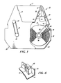
- Figure 1 is a top plan view of the universal ribbon cartridge of this invention, partially broken away to show the universal end-of-ribbon detection system;
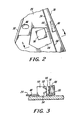
- Figure 2 is an enlarged partial top plan view showing the end-of-ribbon detection system as utilized with one form of light source and detector;
- Figure 3 is a side sectional view taken substantially along line 3-3 of Figure 2;
- Figure 4 is an enlarged partial top plan view similar to that of Figure 2 showing the end-of-ribbon detection system as utilized with another form of light source and detector;
- Figure 5a is a side sectional view taken substantially along line 5-5 of Figure 4 showing one manner in which the light source, detector and compound reflector are utilized;
- Figure 5b is a side sectional view taken substantially along line 5-5 of Figure 4 showing another manner in which the light source, detector and compound reflector are utilized; and
- Figure 6 is a perspective view of the compound reflector in place in the ribbon cartridge.
- With particular reference to the drawings there is illustrated in Figure 1 a
ribbon cartridge 10 made up of upper and lower moldcd plastic interfitting halves denning an interior volume in which a supply spool 12 of inkedribbon material 14 is housed. The ribbon is unspooled and routed through the interior of the cartridge to anoutlet horn 16 from which it exits the cartridge enclosure and traverses aprint region 17 prior to reenteringinlet horn 18 and being collected on a take-up spool (not shown). The usual take-up spool includes acentral shaft 20 which extends outwardly from the top of the cartridge enclosure. A drive roller 22, also extending outwardly from the top of the cartridge enclosure is journalled for rotation in opposing holes in alignment with each other in thebottom wall portion 24 and the top wall portion 26. The drive roller 22 may be driven by the various driving arrangements of the printer models for which this cartridge is compatible, as part of its universality. However, the drive compatibility itself forms no part of the present invention. Ribbon take-up is accomplished by rotating the take-up spool shaft 20 with O-ring 28, which couples the outwardly extending portions ofshaft 20 and drive roller 22. - A
peripheral sidewall 30 extends between thebottom wall 24 and top wall 26. Thewall 30 may be formed integral with either the top wall or the bottom wall, half of the side wall may be formed on each the bottom wall and top wall, or the sidewall may be intermittently integral with the bottom wall and top wall at different portions along the cartridge periphery. Also molded integrally with either the bottom or top walls is anexit guide formation 32 over which the ribbon rides to an opening in theoutlet horn 16. A similar guide formation (not shown) is located at the entrance opening of theinlet horn 18. - In order to control the tension in the
ribbon 14, abrake 34 is provided around thehub 36 of the spool. Thebrake 34 is in the form of a spring wire having one end restrained by moldedpins hub 36, and its other end terminating inguide pin 42 over which theribbon 14 passes. In addition to providing a substantially constant ribbon tension, theguide pin 42 ofbrake 34, together withexit guide formation 32, establishes a path of travel for the ribbon adjacent an end-of-ribbon detection system. - The invention set forth herein relates to the universal end of ribbon detection system which allows an end-of-ribbon indication to be sensed on all Diablo and Xerox impact printers. In the Diablo impact printers the sensing system comprises a light source and light detector combination positioned on the printers in such a location that it must enter the
cartridge enclosure 20 throughopening 44. On the other hand, in the Xerox impact printers, the sensing system comprises a light source and light detector combination positioned on the printers in such a location that it must enter thecartridge enclosure 10 throughopening 46. These sensing system configurations will cooperate with thecompound reflector element 48, as will be described. - In Figures 2 and 3 there is shown the universal cartridge of this invention as mounted upon a Diablo impact printer. When in place, the
opening 44 inbottom wall 24 receives asensor housing structure 50 which penetrates into the interior of the ribbon cartridge and cooperates with the ribbon to indicate an end-of-ribbon condition. This is accomplished by means of asuitable light soure 52, such as in LED, and photo-detector 54 each aimed at theribbon 14. As described, the ribbon is directed along a path defined byguide pin 42 andexit guide formation 32 so as to pass adjacent to thesensor 50. The location of the ribbon plane is such that the reflected light from the light source will impinge upon the photodetector as indicated by the dotted lines. Clearly, if the ribbon plane were further from or nearer to thesensor housing structure 50 the reflected light would "miss" the detector. In normal operation, the photodetector will receive insufficient illumination to trigger a sensing circuit because the inkedribbon 14 will not reflect sufficient light. However, at a location near the end of the ribbon, a segment of highlyreflective material 56, such as metalized Mylar, is introduced in the ribbon for cooperation with the sensing system. Thus, when the light from theLED 52 hits this highlyreflective surface 56, the reflection is received by thephotodetector 54 and triggers the printer's controls to terminate operation thereof until the ribbon is replaced. - In the embodiments of Figures 4, 5a and 5b, the universal ribbon cartridge of this invention is shown mounted upon Xerox impact printers. When in place, the
opening 46 in thebottom wall 24 receives the sensor post 58a or 58b. The cartridges previously utilized with these Xerox printers included internal guide elements to pass the ribbon along the paths shown by the singledot phantom line 60 and the doubledot phantom line 62. Clearly, this is not possible in the present universal cartridge since such a construction would cause the ribbon path to interfere with theDiablo sensor housing 50. The twophantom lines reflective segment 56 must pass in order to cause the light from light sources 64a, 64b to impinge upon detectors 66a, 66b, respectively. The location of these paths has been controlled by the positions of light source and light detector on the sensor posts 58a and 58b and the aimed directions thereof, as present in the various Xerox printers. Furthermore, in the various Xerox printers, the light source and detector combinations can be seen to be reversed. In other words, in Figure 5a the light source 64a is below photodetector 66a whereas in Figure 5b the light source 64b is above photodetector 66b. - With the ribbon plane confined to the path of travel shown, and not along
phantom lines reflective surface 56 to trigger the photodetectors 66a and 66b. Therefore, a new sensing system has been devised to allow the photodetectors in various Xerox impact printer products to be triggered by an end-of-ribbon situation. A cleartransparent segment 68 is shown to be secured to the end ofribbon 14. It may comprise Mylar or any other suitable strong flexible material and may precede or follow thereflective segment 56. - Positioned directly behind the
transparent segment 68, in the direction of the light path shown by the dotted line emanating from thesensor post 58, is acompound reflector element 48 secured tosidewall 30. Theelement 48 is of generally wedge shape, as viewed in Figure 4, in order that it may complement the angle ofsidewall 30 and present its reflective face in a direction substantially normal to the light path. A metal plated molded plastic reflector has been found to operate quite satisfactorily. In order to reflect light from light sources 64a and 64b onto their respective photodetectors 66a and 66b, two collecting surfaces are required. Such an arrangement is necessitated by the fact that the light rays emanating from the light sources diverge in a generally conical manner as illustrated in Figures 5a and 5b. Without a collecting surface the light impinging on a planar reflecting surface would be scattered and would not return to the photodetector with sufficient intensity to trigger the existing sensing circuit. - As illustrated in Figures 5a, 5b and 6, two concave surfaces 7 4 and 72, one above the other, are provided on
element 48. The focal point of each reflective collecting surface corresponds to the location in space of its associated photodetector. Thus, the focal point ofcurved surface 72 coincides with lower photodetector 66b on sensor post 58b and the focal point ofcurved surface 74 coincides with upper photodetector 66a on sensor post 58a. In this manner, although the light rays from light sources 64a and 64b spread and are diffused over their longer distance of travel to the reflective surface, they are collected and focussed upon their respective photodetectors to concentrate sufficient illumination to trigger the printer sensing circuit. Curved reflective surfaces in the form of spherical arcs having their radii equal to the distance to the photodctcctor have been used with good results. Of course, other concave collecting surfaces may also be used satisfactorily. - It should be understood that the present disclosure has been made only by way of example and that numerous changes in details of construction and the combination and arrangement of parts may be resorted to without departing from the true spirit and the scope of the invention as hereinafter claimed.
Claims (9)
1. A ribbon cartridge for an impact printer including a housing (10) containing ribbon supply means (12) and take-up means (20), a ribbon (14) extending between the supply and take-up means (12,20) so as to exit and reenter the housing (10) there between and end of ribbon indicating means including at least one aperture (44,46) in said housing for receiving external sensing means (58), means (42,32) for guiding said ribbon (14) past said aperture(s) (44,46) and reflector means (48) positioned on the side of said ribbon (14) remote from said sensing means (58), said ribbon (14) having a transparent portion (68) near the end of its length.
2. A ribbon cartridge according to claim 1, in which the ribbon includes reflecting means (56) near the end of its length and is guided so that said ribbon reflecting means (56) will coact with one (50) of a plurality of different sensing means (50,58) receivable through said aperture(s) (44,46), said reflector means (48) being arranged to connect through said transparent ribbon portion (68) with at least one other sensing means (58).
3. A ribbon cartridge for an impact printer having a top cover section (26), a bottom cover section (24), a peripheral sidewall section (30) between said top and bottom cover sections, a ribbon supply means (12) providing a length of ribbon (14), ribbon take-up means (20), and ribbon drive means (22) for drawing ribbon from said supply means for collection by said take-up means, characterized by universal end of ribbon indicating means comprising:
at least one aperture (44,46) in said bottom cover section of a size sufficient to allow at least a first, a second or a third sensing means to penetrate into said ribbon cartridge;
means (42,32) for directing said ribbon for movement in a path of travel past said aperture(s) (44,46);
reflecting means (56) located on said ribbon (14) near the end of its length, for use in cooperation with said first sensing means (50);
transparent means (68) located on said ribbon (14) near the end of said ribbon length, for use in cooperation with said second or third sensing means (58a,58b); and
compound reflector means (48) having a first reflective portion (74) for use in cooperation with said second sensing means (58a) and having a second reflective portion (72) for. use in cooperation with said third sensing means (58b), said compound reflector means (48) being positioned on the side of said ribbon (14) remote from said second or third sensing means.
4. A ribbon cartridge according to claim 3, in which said compound reflector means (48) is positioned in abutting relation to said bottom cover section (24) and said sidewall section (30).
5. A ribbon cartridge according to claim 3 or 4, in which said first reflective portion (74) of said compound reflector means (48) is a curved surface shaped and positioned to collect light emanating from a light source (64a) on said second sensing means (58a) and to focus the light so collected upon a light detector (64b) on said second sensing means and said second reflective portion (72) is a curved surface shaped and positioned to collect light emanating from a light source (66a) on said third sensing means (58b) and to focus the light so collected upon a light detector (66b) on said third sensing means.
6. A ribbon cartridge according to claim 5, in which said first and second reflective portions (74,72) are spherical arcs.
7. A ribbon cartridge according to claim 6, in which the center of said first spherical arc (74) is located at the spatial location of the operative position of said light detector (64b) of said second sensing means (58a) and the center of said second spherical arc (72) is located at the spatial location of the operative position of said light detector (66b) of said third sensing means (58b).
8. A ribbon cartrdige according to any of claims 3 to 7, in which said compound reflector means (48) is a molded plastic member whose first and second reflective portions (74,72) are provided with a highly reflective metallized plating.
9. A ribbon cartridge according to any of claims 3 to 8, in which said transparent ribbon means (68) is clear.
Applications Claiming Priority (2)
| Application Number | Priority Date | Filing Date | Title |
|---|---|---|---|
| US310556 | 1981-10-13 | ||
| US06/310,556 US4401394A (en) | 1981-10-13 | 1981-10-13 | Universal end of ribbon sensing system |
Publications (2)
| Publication Number | Publication Date |
|---|---|
| EP0077218A2 true EP0077218A2 (en) | 1983-04-20 |
| EP0077218A3 EP0077218A3 (en) | 1984-03-28 |
Family
ID=23203056
Family Applications (1)
| Application Number | Title | Priority Date | Filing Date |
|---|---|---|---|
| EP82305439A Withdrawn EP0077218A3 (en) | 1981-10-13 | 1982-10-13 | Ribbon cartridge for impact printers |
Country Status (2)
| Country | Link |
|---|---|
| US (1) | US4401394A (en) |
| EP (1) | EP0077218A3 (en) |
Cited By (3)
| Publication number | Priority date | Publication date | Assignee | Title |
|---|---|---|---|---|
| US4921363A (en) * | 1985-01-26 | 1990-05-01 | Sharp Kabushiki Kaisha | Thermal transfer printer having independent carriage scanning mechanism and ribbon winding motor |
| EP0574165A1 (en) * | 1992-06-05 | 1993-12-15 | Esselte Dymo N.V. | Printing apparatus |
| EP0692387A1 (en) * | 1994-07-15 | 1996-01-17 | Brother Kogyo Kabushiki Kaisha | Tape-shaped label producing device |
Families Citing this family (17)
| Publication number | Priority date | Publication date | Assignee | Title |
|---|---|---|---|---|
| CH647982A5 (en) * | 1982-05-14 | 1985-02-28 | Hermes Precisa International | CASSETTE FOR A WRITING MACHINE COMPRISING A DEVICE FOR DETECTING THE END OF THE TAPE. |
| IT1157030B (en) * | 1982-06-07 | 1987-02-11 | Olivetti Accessori Spa | CARTRIDGE FOR A WRITING TAPE WITH CONTRAST ELEMENT OF WRITING MACHINES |
| JPS6061283A (en) * | 1983-09-14 | 1985-04-09 | Star Seimitsu Kk | Winding end detector for belt form material |
| JPS6067948U (en) * | 1983-10-14 | 1985-05-14 | ブラザー工業株式会社 | printing ribbon cassette |
| US4650357A (en) * | 1984-04-12 | 1987-03-17 | Xerox Corporation | Universal ribbon cartridge |
| US4623271A (en) * | 1984-05-14 | 1986-11-18 | Primages Inc. | Ink ribbon cartridge for a printer including means for transversely displacing and advancing the ink ribbon in the cartridge |
| US4586837A (en) * | 1984-08-27 | 1986-05-06 | International Business Machines Corp. | Ink ribbon cartridge indication system for printer |
| JPS61248773A (en) * | 1985-04-26 | 1986-11-06 | Canon Inc | Ink ribbon cassette |
| US4707155A (en) * | 1985-12-24 | 1987-11-17 | International Business Machines Corporation | Re-inkable ribbon transport system |
| US5032032A (en) * | 1986-06-04 | 1991-07-16 | Primages, Inc. | Ribbon cassette responsive to ribbon breakage |
| DE3700636C1 (en) * | 1987-01-12 | 1988-05-26 | Olympia Aeg | Ribbon device in typewriters or similar office machines |
| IT1219278B (en) * | 1988-05-09 | 1990-05-03 | Olivetti & Co Spa | CARTRIDGE FOR A CORRECTION TAPE |
| JPH0222090A (en) * | 1988-07-12 | 1990-01-24 | Matsushita Electric Ind Co Ltd | Printing apparatus |
| IT1231883B (en) * | 1989-03-20 | 1992-01-14 | Olivetti & Co Spa | CARTRIDGE FOR A WRITING TAPE OF WRITING MACHINES |
| US5507583A (en) * | 1994-12-22 | 1996-04-16 | Premark Feg Corporation | Label printer having a position sensor |
| US6989180B2 (en) * | 2003-10-09 | 2006-01-24 | Ncr Corporation | Thermal transfer ribbon with end of ribbon markers |
| US7390134B2 (en) * | 2005-04-20 | 2008-06-24 | Printronix, Inc. | Ribbon identification |
Family Cites Families (4)
| Publication number | Priority date | Publication date | Assignee | Title |
|---|---|---|---|---|
| US2174351A (en) * | 1936-12-30 | 1939-09-26 | Underwood Elliott Fisher Co | Typewriter ribbon |
| US4115013A (en) * | 1977-03-30 | 1978-09-19 | Xerox Corporation | End-of-ribbon sensor device |
| US4195913A (en) * | 1977-11-09 | 1980-04-01 | Spawr Optical Research, Inc. | Optical integration with screw supports |
| US4307969A (en) * | 1979-10-01 | 1981-12-29 | Wordex | Universal ribbon cartridge |
-
1981
- 1981-10-13 US US06/310,556 patent/US4401394A/en not_active Expired - Lifetime
-
1982
- 1982-10-13 EP EP82305439A patent/EP0077218A3/en not_active Withdrawn
Cited By (5)
| Publication number | Priority date | Publication date | Assignee | Title |
|---|---|---|---|---|
| US4921363A (en) * | 1985-01-26 | 1990-05-01 | Sharp Kabushiki Kaisha | Thermal transfer printer having independent carriage scanning mechanism and ribbon winding motor |
| US5601375A (en) * | 1992-05-06 | 1997-02-11 | Esselte N.V. | Automatic tape detecting and tape width identifying printing apparatus and tape holder |
| EP0574165A1 (en) * | 1992-06-05 | 1993-12-15 | Esselte Dymo N.V. | Printing apparatus |
| US5456545A (en) * | 1992-06-05 | 1995-10-10 | Esselte Dymo N.V. | Tape printing apparatus and tape holding case |
| EP0692387A1 (en) * | 1994-07-15 | 1996-01-17 | Brother Kogyo Kabushiki Kaisha | Tape-shaped label producing device |
Also Published As
| Publication number | Publication date |
|---|---|
| EP0077218A3 (en) | 1984-03-28 |
| US4401394A (en) | 1983-08-30 |
Similar Documents
| Publication | Publication Date | Title |
|---|---|---|
| US4401394A (en) | Universal end of ribbon sensing system | |
| US5087137A (en) | Ribbon assembly including indicia to identify operating parameters and ribbon depletion | |
| US5393149A (en) | Color video printer and an ink ribbon cartridge used therein | |
| US6396070B1 (en) | Adjustable sensor assembly for printers | |
| EP0110634A2 (en) | Ink jet printer | |
| KR19990082175A (en) | Printer ribbon identification sensor | |
| OA05968A (en) | Ribbon cartridge for typewriter and its driving mechanism. | |
| US5383733A (en) | Ribbon cassette for a printer | |
| ES514116A0 (en) | "A CASSETTE DEVICE FOR AN INK JET PRINTER". | |
| WO1996019353A1 (en) | A printer having a position sensor | |
| JPH06171824A (en) | Printer and tape holding case used for the same | |
| WO1996019353A9 (en) | A printer having a position sensor | |
| GB2220384A (en) | Identifying cassettes used in selective printing machines | |
| US5290114A (en) | Ink ribbon unit and ink ribbon cassette | |
| CA1227965A (en) | Multicolor dot matrix printing system | |
| JPS6154977A (en) | Printer | |
| US4491430A (en) | Ribbon monitor for ribbon cassette | |
| JPH0651417B2 (en) | Ribbon cartridge | |
| US4492483A (en) | Means for detecting the end of a ribbon for typewriters | |
| US4612446A (en) | Web terminal detecting device | |
| GB2161754A (en) | Two-piece tape/ribbon cartridge | |
| US4925324A (en) | Color ink ribbon for thermal printer | |
| JPH0342190B2 (en) | ||
| JPS646919A (en) | Radiograph reader | |
| JPH0110219Y2 (en) |
Legal Events
| Date | Code | Title | Description |
|---|---|---|---|
| PUAI | Public reference made under article 153(3) epc to a published international application that has entered the european phase |
Free format text: ORIGINAL CODE: 0009012 |
|
| AK | Designated contracting states |
Designated state(s): DE FR GB |
|
| PUAL | Search report despatched |
Free format text: ORIGINAL CODE: 0009013 |
|
| AK | Designated contracting states |
Designated state(s): DE FR GB |
|
| STAA | Information on the status of an ep patent application or granted ep patent |
Free format text: STATUS: THE APPLICATION IS DEEMED TO BE WITHDRAWN |
|
| 18D | Application deemed to be withdrawn |
Effective date: 19841129 |
|
| RIN1 | Information on inventor provided before grant (corrected) |
Inventor name: HUME, JAMES G. Inventor name: FOSTER, HAROLD S. Inventor name: SIDVERS, JOHN |