EP0077229A1 - Schutzschalterauslösevorrichtung - Google Patents
Schutzschalterauslösevorrichtung Download PDFInfo
- Publication number
- EP0077229A1 EP0077229A1 EP82401698A EP82401698A EP0077229A1 EP 0077229 A1 EP0077229 A1 EP 0077229A1 EP 82401698 A EP82401698 A EP 82401698A EP 82401698 A EP82401698 A EP 82401698A EP 0077229 A1 EP0077229 A1 EP 0077229A1
- Authority
- EP
- European Patent Office
- Prior art keywords
- hooking
- rollers
- tongue
- hook
- spline
- Prior art date
- Legal status (The legal status is an assumption and is not a legal conclusion. Google has not performed a legal analysis and makes no representation as to the accuracy of the status listed.)
- Granted
Links
Images
Classifications
-
- H—ELECTRICITY
- H01—ELECTRIC ELEMENTS
- H01H—ELECTRIC SWITCHES; RELAYS; SELECTORS; EMERGENCY PROTECTIVE DEVICES
- H01H71/00—Details of the protective switches or relays covered by groups H01H73/00 - H01H83/00
- H01H71/10—Operating or release mechanisms
- H01H71/50—Manual reset mechanisms which may be also used for manual release
- H01H71/505—Latching devices between operating and release mechanism
- H01H2071/506—Latching devices between operating and release mechanism using balls or rollers in the latching device
Definitions
- the invention relates to a device for tripping an electric circuit breaker according to the preamble of claim 1.
- a known triggering device of the kind mentioned (US-A-2,662,136) uses locking members or rollers with rolling movement, that is to say with low friction. These roller hooks are capable of resuming large reactions without requiring a significant unlocking force and are particularly suitable for circuit breakers of high caliber using springs of large force.
- the hooking force of the hook derives a rolling force of the rollers and sliding of the tongue inserted between the two rollers towards an unlocked position.
- This self-unlocking is hampered by the attraction of the tongue by an electromagnet, the triggering resulting from the release of the tongue by bypassing the flux of the electromagnet.
- This known system has failures due to sticking and matting of the contacting surfaces which transmit the large force exerted by the hook. This sticking, which brakes or prevents tripping of the circuit breaker, is frequent when the circuit breaker rarely works and failure to trip can have disastrous consequences.
- the present invention aims to remedy these drawbacks and as characterized in the claims it allows the production of a reliable and simple triggering device.
- Triggering takes place in two successive phases, a first phase of pivoting of the tongue, imposed by the action of the triggering lever, which brings about on the one hand a disengagement of the tongue from the stop and on the other hand a micro-displacement of the support points of the rollers on the tongue and a second phase of self-displacement of the tongue and the rollers.
- the displacement force of the tongue is derived from the hooking force of the hook and is all the greater the greater the support force and therefore the risk of sticking.
- the trigger lever acts transversely on the tongue and it will appear from the description below that the micro-displacements generated by this transverse displacement of the tongue, break the bonding forces and initiate the sliding movement of the tongue.
- the tongue inserted between the latching rollers is biased in the locking position by the latching force of the hook on Rolls; Coils. This self-locking involves a higher unlocking force, which can easily be kept within acceptable limits.
- rollers which can be balls or any other body of revolution, are advantageously mounted in a cage, biased in the locking position by a spring. As soon as the hook is released the rollers come back automatically in the locked position, as well as the tongue also subjected to a return spring. When resetting the circuit breaker, the hook temporarily pushes the rollers back to catch on, and during this maneuver the discharged rollers slide easily on the tongue and the support.
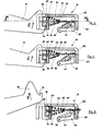
- a hook 10 of a mechanism (not shown) of an electric circuit breaker cooperates with a roller hooking, designated by the general reference 12.
- the circuit breaker can be of the molded case type having an operating handle manual and an automatic trigger on fault.
- Such circuit breakers are well known to specialists under the trade name COMPACT, and they include an energy storage spring (not shown) for opening the contacts when the hook 10 is released under the action of the trip device.
- the beak-shaped end 14 of the hook 10 abuts against a roller 16, lower in the figures, of a pair of superimposed rollers 16, 18 mounted in a holding cage 20.
- the upper roller 18 is supported on a support surface 22 of a fixed support 24, and the roller assembly 16, 18, cage 20 is mounted with limited sliding in the fixed support 24 parallel to the support surface 22 between the rollers 16,18 is inserted the end of a hooking tongue 26, which extends substantially parallel to the bearing surface 22 through the cage 20.
- the opposite end 28 of the tongue attachment 26 cooperates, in the locked position, with a stop plate 30 of the fixed support 24, preventing sliding of the tongue 26 to the right in the figures.
- a trigger lever 32 rotatably mounted on an axis 34, strikes, when triggered, the end 28 to lift the latter above the edge of the stop plate 30 and unlock the tongue 26, which can then slide freely.
- the hooking force of the hook 10 is transmitted by the lower roller 16, the tongue 26 and the upper roller 18 to the fixed support 24.
- the bearing surface 22 is slightly inclined to form with the surface 36 of the spout 14 a corner at a small angle and the hooking force of the hook 10 tends to drive the rollers 16, 18 outside this corner to the right in the figures.
- the tongue 26 is locked, any displacement by sliding of the rollers 16, 18 is made impossible by the high friction forces of the rollers on the tongue 26 kept fixed and on the bearing surfaces 22, 36.
- the rollers 16, 18 can roll by imposing on the tongue 26 a double movement to the right in the directions indicated by the arrows in the figures.
- Rolling friction is very low, even in the presence of a high latching force. It's easy to choose the angle of bearing surfaces 22, 36 to have an unlocking force, derived from the latching force, sufficient to move the roller assembly 16, 18, tongue 26 by rotation for self-unlocking of the hook 10, but insufficient for a sliding movement.
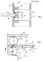
- the spout 14 escapes after a predetermined displacement of the rollers 16. 18 to the right and the released hook 10 pivots towards the release position, the cage 20 and the support 24 of course having a groove 38 for passage of the hook 10 (FIG. 4).
- the tongue 26, clamped between the rollers 16, 18, is urged by this clamping force towards a position perpendicular to the line O 1 O 2 of the centers of the rollers 16, 18, which. corresponds to the locking position of the tongue 26.
- the tongue 26 tends to pivot clockwise while pressing the trigger lever 32 and the stop plate 30.
- the position of locking is a stable position avoiding any untimely triggering.
- the trigger lever 32 When triggered, the trigger lever 32 rotates the tongue 26 anti-clockwise in the figures to raise the end 28 above the edge of the stop plate 30 and unlock the tongue 26. During this pivoting, the points B, B 2 of contact of the rollers 16, 18 and of the tongue 26 are modified, which breaks the bonding forces and initiates self-unlocking by rolling the rollers 16, 18 to the right. . These displacements of the contact points B 1 , B 2 are very small but sufficient to eliminate any risk of blocking the attachment. The trigger lever 32 must overcome the sliding friction of the end 28 on the stop plate 30 and the centering force imposed by the rollers 16, 18, but these forces are easily controllable and can possibly be reduced.
- the hook 10 pivots in the opposite direction and on the way pushes the rollers 16, 18, which are unloaded, to the right, before coming to hang in the position shown in FIG. 1.
- the assembly is simple and reliable and allows control of the significant fastening forces essential in high-caliber circuit breakers.
Landscapes
- Breakers (AREA)
- Orthopedics, Nursing, And Contraception (AREA)
Applications Claiming Priority (2)
| Application Number | Priority Date | Filing Date | Title |
|---|---|---|---|
| FR8118841 | 1981-10-05 | ||
| FR8118841A FR2514196A1 (fr) | 1981-10-05 | 1981-10-05 | Dispositif de declenchement d'un disjoncteur electrique |
Publications (2)
| Publication Number | Publication Date |
|---|---|
| EP0077229A1 true EP0077229A1 (de) | 1983-04-20 |
| EP0077229B1 EP0077229B1 (de) | 1985-04-10 |
Family
ID=9262814
Family Applications (1)
| Application Number | Title | Priority Date | Filing Date |
|---|---|---|---|
| EP19820401698 Expired EP0077229B1 (de) | 1981-10-05 | 1982-09-20 | Schutzschalterauslösevorrichtung |
Country Status (6)
| Country | Link |
|---|---|
| EP (1) | EP0077229B1 (de) |
| JP (1) | JPS5870657U (de) |
| CA (1) | CA1221397A (de) |
| DE (1) | DE3263007D1 (de) |
| ES (1) | ES8306425A1 (de) |
| FR (1) | FR2514196A1 (de) |
Citations (3)
| Publication number | Priority date | Publication date | Assignee | Title |
|---|---|---|---|---|
| US2662136A (en) * | 1951-03-14 | 1953-12-08 | Hitachi Ltd | High speed trip device for electric circuit breakers |
| GB850647A (en) * | 1956-03-06 | 1960-10-05 | British Thomson Houston Co Ltd | Improvements in high speed tripping mechanisms |
| DE1192295B (de) * | 1962-04-06 | 1965-05-06 | Bbc Brown Boveri & Cie | UEbertotpunktgesperre mit sich aufeinander abstuetzenden Waelzkoerpern |
-
1981
- 1981-10-05 FR FR8118841A patent/FR2514196A1/fr active Granted
-
1982
- 1982-09-16 CA CA000411563A patent/CA1221397A/en not_active Expired
- 1982-09-20 EP EP19820401698 patent/EP0077229B1/de not_active Expired
- 1982-09-20 DE DE8282401698T patent/DE3263007D1/de not_active Expired
- 1982-09-29 ES ES516083A patent/ES8306425A1/es not_active Expired
- 1982-10-04 JP JP15079582U patent/JPS5870657U/ja active Granted
Patent Citations (3)
| Publication number | Priority date | Publication date | Assignee | Title |
|---|---|---|---|---|
| US2662136A (en) * | 1951-03-14 | 1953-12-08 | Hitachi Ltd | High speed trip device for electric circuit breakers |
| GB850647A (en) * | 1956-03-06 | 1960-10-05 | British Thomson Houston Co Ltd | Improvements in high speed tripping mechanisms |
| DE1192295B (de) * | 1962-04-06 | 1965-05-06 | Bbc Brown Boveri & Cie | UEbertotpunktgesperre mit sich aufeinander abstuetzenden Waelzkoerpern |
Also Published As
| Publication number | Publication date |
|---|---|
| EP0077229B1 (de) | 1985-04-10 |
| ES516083A0 (es) | 1983-06-01 |
| FR2514196B1 (de) | 1984-12-28 |
| JPH0121465Y2 (de) | 1989-06-27 |
| ES8306425A1 (es) | 1983-06-01 |
| DE3263007D1 (en) | 1985-05-15 |
| FR2514196A1 (fr) | 1983-04-08 |
| CA1221397A (en) | 1987-05-05 |
| JPS5870657U (ja) | 1983-05-13 |
Similar Documents
| Publication | Publication Date | Title |
|---|---|---|
| EP0688581B1 (de) | Entkuppelbares selbstblockierendes Abseilgerät | |
| EP0274287B1 (de) | Türschloss, insbesondere für Kraftfahrzeuge | |
| EP0534833B1 (de) | Verriegelungsvorrichtung mit Hakenriegel | |
| EP0803268B1 (de) | Scheibe mit Drehflansch und integrierter Klemme | |
| EP0150756B1 (de) | Vorrichtung zur Steuerung eines elektrischen Leistungsschalters | |
| EP2018894A1 (de) | Selbstblockierendes Abseilgerät mit entkoppelbarem Griff | |
| EP0859648A1 (de) | Automatisches fallschutzgerät für grosse höhenarbeit | |
| FR2687249A1 (fr) | Mecanisme de commande d'un disjoncteur a boitier moule. | |
| EP0593369A1 (de) | Sicherheitsabseilvorrichtung | |
| EP2407413A1 (de) | Riemenscheibe mit entriegelbarer Blockiervorrichtung | |
| FR2477991A1 (fr) | Dispositif de fixation d'une ferrure reglable dans differentes positions, en particulier d'une ferrure pour sieges de vehicule | |
| FR2634705A1 (fr) | Enrouleur de ceinture de securite pour vehicule | |
| FR2669988A1 (fr) | Soupape thermostatique. | |
| EP0338930A1 (de) | Lastschalter oder Differential-Lastschalter | |
| EP0161946B1 (de) | An einen Schutzschalter ankuppelbare Zusatzeinheit | |
| EP0066322B1 (de) | Bremsvorrichtung eines metallischen Messbandes | |
| EP0077229B1 (de) | Schutzschalterauslösevorrichtung | |
| FR2721523A1 (fr) | Descendeur à verrouillage de la poulie pour le blocage permanent de la corde. | |
| EP0506503B1 (de) | Schlossmechanismus für Lastschalter | |
| EP0305485B1 (de) | Schloss mit elektromagnetischer verriegelung/entriegelung | |
| FR3097075A1 (fr) | Mécanisme indicateur de défaut de court-circuit et disjoncteur comprenant un tel mécanisme indicateur de défaut de court-circuit. | |
| FR2919195A1 (fr) | Descendeur autobloquant a poignee debrayable. | |
| EP1023513B1 (de) | Sicherheitsschloss, insbesondere für aufzugsschachttür | |
| EP0974421B1 (de) | Greifer mit selbstverriegelung und selbstentriegelung | |
| FR2683580A1 (fr) | Dispositif de verrouillage de securite a crochet basculant. |
Legal Events
| Date | Code | Title | Description |
|---|---|---|---|
| PUAI | Public reference made under article 153(3) epc to a published international application that has entered the european phase |
Free format text: ORIGINAL CODE: 0009012 |
|
| AK | Designated contracting states |
Designated state(s): BE CH DE GB IT LI NL SE |
|
| 17P | Request for examination filed |
Effective date: 19830823 |
|
| ITF | It: translation for a ep patent filed | ||
| GRAA | (expected) grant |
Free format text: ORIGINAL CODE: 0009210 |
|
| AK | Designated contracting states |
Designated state(s): BE CH DE GB IT LI NL SE |
|
| REF | Corresponds to: |
Ref document number: 3263007 Country of ref document: DE Date of ref document: 19850515 |
|
| PLBE | No opposition filed within time limit |
Free format text: ORIGINAL CODE: 0009261 |
|
| STAA | Information on the status of an ep patent application or granted ep patent |
Free format text: STATUS: NO OPPOSITION FILED WITHIN TIME LIMIT |
|
| 26N | No opposition filed | ||
| PGFP | Annual fee paid to national office [announced via postgrant information from national office to epo] |
Ref country code: CH Payment date: 19890927 Year of fee payment: 8 |
|
| PGFP | Annual fee paid to national office [announced via postgrant information from national office to epo] |
Ref country code: NL Payment date: 19890930 Year of fee payment: 8 |
|
| PG25 | Lapsed in a contracting state [announced via postgrant information from national office to epo] |
Ref country code: LI Effective date: 19900930 Ref country code: CH Effective date: 19900930 |
|
| PG25 | Lapsed in a contracting state [announced via postgrant information from national office to epo] |
Ref country code: NL Effective date: 19910401 |
|
| NLV4 | Nl: lapsed or anulled due to non-payment of the annual fee | ||
| REG | Reference to a national code |
Ref country code: CH Ref legal event code: PL |
|
| ITTA | It: last paid annual fee | ||
| EAL | Se: european patent in force in sweden |
Ref document number: 82401698.4 |
|
| PGFP | Annual fee paid to national office [announced via postgrant information from national office to epo] |
Ref country code: SE Payment date: 19950918 Year of fee payment: 14 |
|
| PGFP | Annual fee paid to national office [announced via postgrant information from national office to epo] |
Ref country code: BE Payment date: 19951031 Year of fee payment: 14 |
|
| PGFP | Annual fee paid to national office [announced via postgrant information from national office to epo] |
Ref country code: GB Payment date: 19960911 Year of fee payment: 15 |
|
| PGFP | Annual fee paid to national office [announced via postgrant information from national office to epo] |
Ref country code: DE Payment date: 19960914 Year of fee payment: 15 |
|
| PG25 | Lapsed in a contracting state [announced via postgrant information from national office to epo] |
Ref country code: SE Effective date: 19960921 |
|
| PG25 | Lapsed in a contracting state [announced via postgrant information from national office to epo] |
Ref country code: BE Effective date: 19960930 |
|
| BERE | Be: lapsed |
Owner name: MERLIN GERIN Effective date: 19960930 |
|
| EUG | Se: european patent has lapsed |
Ref document number: 82401698.4 |
|
| PG25 | Lapsed in a contracting state [announced via postgrant information from national office to epo] |
Ref country code: GB Free format text: LAPSE BECAUSE OF NON-PAYMENT OF DUE FEES Effective date: 19970920 |
|
| GBPC | Gb: european patent ceased through non-payment of renewal fee |
Effective date: 19970920 |
|
| PG25 | Lapsed in a contracting state [announced via postgrant information from national office to epo] |
Ref country code: DE Free format text: LAPSE BECAUSE OF NON-PAYMENT OF DUE FEES Effective date: 19980603 |