EP0077234A1 - Device for dry de-scaling of travelling metallurgical products - Google Patents
Device for dry de-scaling of travelling metallurgical products Download PDFInfo
- Publication number
- EP0077234A1 EP0077234A1 EP82401736A EP82401736A EP0077234A1 EP 0077234 A1 EP0077234 A1 EP 0077234A1 EP 82401736 A EP82401736 A EP 82401736A EP 82401736 A EP82401736 A EP 82401736A EP 0077234 A1 EP0077234 A1 EP 0077234A1
- Authority
- EP
- European Patent Office
- Prior art keywords
- product
- abrasive
- housing
- suction
- chamber
- Prior art date
- Legal status (The legal status is an assumption and is not a legal conclusion. Google has not performed a legal analysis and makes no representation as to the accuracy of the status listed.)
- Withdrawn
Links
Images

Classifications
-
- B—PERFORMING OPERATIONS; TRANSPORTING
- B24—GRINDING; POLISHING
- B24C—ABRASIVE OR RELATED BLASTING WITH PARTICULATE MATERIAL
- B24C1/00—Methods for use of abrasive blasting for producing particular effects; Use of auxiliary equipment in connection with such methods
- B24C1/08—Methods for use of abrasive blasting for producing particular effects; Use of auxiliary equipment in connection with such methods for polishing surfaces, e.g. smoothing a surface by making use of liquid-borne abrasives
- B24C1/086—Descaling; Removing coating films
-
- B—PERFORMING OPERATIONS; TRANSPORTING
- B24—GRINDING; POLISHING
- B24C—ABRASIVE OR RELATED BLASTING WITH PARTICULATE MATERIAL
- B24C3/00—Abrasive blasting machines or devices; Plants
- B24C3/08—Abrasive blasting machines or devices; Plants essentially adapted for abrasive blasting of travelling stock or travelling workpieces
- B24C3/10—Abrasive blasting machines or devices; Plants essentially adapted for abrasive blasting of travelling stock or travelling workpieces for treating external surfaces
- B24C3/12—Apparatus using nozzles
Definitions
- This hydraulic descaling has the drawback of causing a reduction in the average temperature of the slabs by approximately 20 ° C., a reduction which is compensated for by a greater heating of the slabs at the start. Hydraulic descaling is therefore not very advantageous from the point of view of thermal balance. This drop in temperature is all the more important the lower the rolling speed. And in this case, the hydraulic descaling is no longer usable.
- the means for preventing the sand from passing from the suction compartments to the outside of the housing are constituted by two pairs of metal brushes fixed to the external wall of the suction compartments, the brushes of each pair being placed so as to be in contact respectively with each of the faces to be descaled from the product.
- the device according to the invention may also include, inside the abrasion chamber, means for preventing the abrasive from passing into the lateral suction compartments.
- These means may consist of two pairs of metal plates, the plates of each pair being arranged near the walls of the abrasion chamber and on either side of the product, said plates being arranged so as to be in contact, by one on their side, respectively with each of the faces to be descaled from the product .
- Figures 2-A and 2-B show a system according to which the sandblast sweeps the entire width of the product.
- the injection nozzle 12 is mounted on a support 26 which has at one of its ends a threaded sleeve 27 and at the other end a smooth sleeve 28.
- two rods, respectively working 29 and guiding 30, are arranged parallel to each other, through the sanding chamber 4, above the product and perpendicular to the direction of travel of the latter .
Landscapes
- Engineering & Computer Science (AREA)
- Mechanical Engineering (AREA)
- Cleaning In General (AREA)
Abstract
Dispositif de décalaminage à sec de produits métallurgiques en défilement constitué par un boîtier (1) divisé en trois éléments de volume au moins, alignés pour pouvoir être traversés en ligne droite par le produit en défilement (2): une chambre centrale d'abrasion (4) ouverte à sa partie inférieure pour la récupération de l'abrasif et de la calamine, et bordée de chaque côté par des compartiments d'aspiration (3, 5) respectivement à l'entrée et à la sortie du boîtier, équipés de moyens pour empêcher une propagation de l'abrasif en dehors du boîtier au travers des ouvertures de passage du produit (2). La chambre d'abrasion (4), est pourvue intérieurement d'au moins une buse (12) d'injection d'abrasif pulvérulent placée en regard des faces à décalaminer du produit, ladite buse étant montée mobile sur le boîtier (1) pour permettre un balayage de la surface à décaliminer perpendiculairement à la direction de défilement du produit (2). L'invention s'applique avantageusement aux produits à faible vitesse de défilement, notamment aux brames d'acier à l'entrée d'un laminoir planétaire.Device for dry descaling of moving metallurgical products consisting of a housing (1) divided into at least three volume elements, aligned so that they can be crossed in a straight line by the moving product (2): a central abrasion chamber ( 4) open at its lower part for the recovery of the abrasive and the scale, and bordered on each side by suction compartments (3, 5) respectively at the inlet and at the outlet of the housing, equipped with means to prevent spread of the abrasive outside the housing through the product passage openings (2). The abrasion chamber (4) is provided internally with at least one nozzle (12) for injecting powdered abrasive placed opposite the faces to be descaled from the product, said nozzle being mounted movably on the housing (1) for allow a sweep of the surface to be decaliminated perpendicular to the direction of travel of the product (2). The invention advantageously applies to products with low running speed, in particular to steel slabs at the entrance to a planetary rolling mill.
Description
La présente invention concerne le décalaminage de produits métallurgiques en défilement, notamment des produits portés à température avant leur laminage. Plus précisément, l'invention a trait au décalaminage à sec par projection d'un abrasif pulvérulent, tel que du sable, et s'applique avantageusement à des produits à vitesse de défilement relativement faible, par exemple des. brames d'acier à l'entrée d'une cage de laminoir à fort taux de réduction, comme notamment un laminoir planétaire.The present invention relates to descaling of metallurgical products in movement, in particular products brought to temperature before their rolling. More specifically, the invention relates to dry descaling by spraying a powdery abrasive, such as sand, and advantageously applies to products with a relatively low running speed, for example. steel slabs at the entrance to a rolling mill stand with a high reduction rate, such as a planetary rolling mill.
On sait que lors de l'opération de réchauffage des brames avant laminage, il y a formation d'une couche de calamine qui entraine de graves défauts de surface sur les tôles obtenues ultérieurement.It is known that during the reheating operation of the slabs before rolling, there is the formation of a layer of scale which causes serious surface defects on the sheets obtained subsequently.
On sait également que l'élimination de la calamine peut s'effectuer par décalaminage hydraulique en arrosant les brames par jets d'eau à haute pression.It is also known that the removal of scale can be carried out by hydraulic descaling by spraying the slabs with high pressure water jets.
Ce décalaminage hydraulique présente l'inconvénient d'entrainer une diminution de la température moyenne des brames d'environ 20° C, diminution que l'on compense par un réchauffage des brames au départ plus important. Le décalaminage hydraulique n'est donc pas très avantageux du point de vue bilan thermique. Cette baisse de température est d'ailleurs d'autant plus importante que la vitesse de laminage est faible. Et dans ce cas, le décalaminage hydraulique n'est donc plus utilisable.This hydraulic descaling has the drawback of causing a reduction in the average temperature of the slabs by approximately 20 ° C., a reduction which is compensated for by a greater heating of the slabs at the start. Hydraulic descaling is therefore not very advantageous from the point of view of thermal balance. This drop in temperature is all the more important the lower the rolling speed. And in this case, the hydraulic descaling is no longer usable.
On connait également des techniques de décalaminage à sec qui consistent à projeter sur la surface calaminée un flux à grande vitesse de particules abrasives, généralement du sable.Dry descaling techniques are also known, which consist in projecting onto the burnt surface a high speed flow of abrasive particles, generally sand.
Ces techniques de décalaminage à sec ont, comme on le comprend, un effet de refroidissement limité sur le produit, et en tous cas sensiblement plus réduit que le décalaminage hydraulique.These dry descaling techniques have, as we understand, a limited cooling effect on the product, and in any case significantly more reduced than hydraulic descaling.
Toutefois, les dispositifs de sablage utilisés doivent être conçus de manière à confiner le plus possible la zone de sablage pour éviter la formation intempestive de poussières dans l'atelier. De plus, la surface décalaminée doit être exempte de particules d'abrasif avant le passage du produit entre les cylindres de laminage.However, the sanding devices used must be designed so as to confine the sanding area as much as possible to avoid inadvertent formation of dust in the workshop. In addition, the descaled surface must be free of abrasive particles before the product passes between the rolling rolls.
On connait un dispositif de ce type (Brevet U.S. n° 1.842.619) constitué d'un bottier comprenant une chambre centrale de sablage placée entre deux compartiments d'aspiration équipés de moyens de brossage pour éliminer le sable de la surface du produit à l'entrée, mais surtout à la sortie du boitier. Cependant, un tel dispositif apparait avoir été conçu spécialement pour des bandes de faible épaisseur à vitesse de passage élevée, ce qui le rend conséquemment mal adapté au traitement de produits épais comme les brames à faible vitesse de défilement.A device of this type is known (US Patent No. 1,842,619) consisting of a shoemaker comprising a central sanding chamber placed between two suction compartments equipped with brushing means to remove the sand from the surface of the product at l 'entry, but especially at the exit of the case. However, such a device appears to have been designed especially for strips of small thickness at high speed of passage, which consequently makes it unsuitable for the treatment of thick products such as slabs with low running speed.
La présente invention a précisément pour but de permettre un décalaminage à sec avant laminage de produits épais à faible vitesse de défilement. Un autre but est de proposer un dispositif de décalaminage à sec par projection de particules solides abrasives qui soit de conception souple, d'entretien aisé et de fonctionnement fiable.The object of the present invention is precisely to allow dry descaling before rolling thick products at low running speed. Another object is to propose a device for dry descaling by projection of solid abrasive particles which is of flexible design, easy maintenance and reliable operation.
Avec ces objectifs en vue, l'invention a pour objet un dispositif de décalaminage à sec de produits métallurgiques en défilement, constitué par un boîtier divisé en trois éléments de volume alignés traversés par le produit en défilement : une chambre centrale d'abrasion ouverte à sa partie inférieure pour la récupération de l'abrasif et de la calamine, et bordée de chaque côté par des compartiments d'aspiration équipés de moyens pour empêcher l'abrasif de se propager en dehors du boîtier par les ouvertures de passage du produit à décalaminer. La chambre d'abrasion est pourvue intérieurement d'au moins une buse d'injection d'abrasif pulvérulent en regard des faces à décalaminer du produit, cette buse étant montée mobile pour permettre un balayage des faces perpendiculairement à la direction de défilement du produit.With these objectives in view, the subject of the invention is a device for dry descaling of moving metallurgical products, consisting of a housing divided into three aligned volume elements traversed by the moving product: a central abrasion chamber open to its lower part for the recovery of the abrasive and of the scale, and bordered on each side by suction compartments equipped with means to prevent the abrasive from spreading outside the casing through the openings for the passage of the product to be descaled . The abrasion chamber is internally provided with at least one nozzle for injecting powdered abrasive opposite the faces to be descaled from the product, this nozzle being mounted so as to allow scanning of the faces perpendicular to the direction of travel of the product.
Selon une forme de réalisation, la buse est montée sur un mécanisme de translation assurant un mouvement de "va et vient".According to one embodiment, the nozzle is mounted on a translation mechanism ensuring a "back and forth" movement.
Selon un mode de réalisation, les moyens pour empêcher le sable de passer des compartiments d'aspiration à l'extérieur du boîtier sont constitués par deux paires de brosses métalliques fixées sur la paroi extérieure des compartiments d'aspiration, les brosses de chaque paire étant placées de façon à être en contact respectivement avec chacune des faces à décalaminer du produit.According to one embodiment, the means for preventing the sand from passing from the suction compartments to the outside of the housing are constituted by two pairs of metal brushes fixed to the external wall of the suction compartments, the brushes of each pair being placed so as to be in contact respectively with each of the faces to be descaled from the product.
Le dispositif conforme à l'invention peut comporter en outre des moyens pour empêcher le sable de passer de la chambre d'abrasion au compartiment d'aspiration "aval", par lequel sort le produit décalaminé. Ces moyens peuvent être, par exemple, constitués par deux brosses métalliques fixées sur la paroi intérieure de ce compartiment d'aspiration et placées de façon à être en contact respectivement avec chacune des faces à décalaminer du produit.The device according to the invention may further comprise means for preventing the sand from passing from the abrasion chamber to the "downstream" suction compartment, through which the decalaminated product exits. These means can be, for example, constituted by two metal brushes fixed to the inner wall of this suction compartment and placed so as to be in contact respectively with each of the faces to be descaled from the product.
Le dispositif selon l'invention peut également comporter, à l'intérieur de la chambre d'abrasion des moyens pour empêcher l'abrasif de passer dans les compartiments d'aspiration latéraux. Ces moyens peuvent être constitués par deux paires de plaques métalliques, les plaques de chaque paire étant disposées à proximité des parois de la chambre d'abrasion et de part et d'autre du produit, lesdites plaques étant agencées de façon à être en contact, par un de leur côté, respectivement avec chacune des faces à décalaminer du produit.The device according to the invention may also include, inside the abrasion chamber, means for preventing the abrasive from passing into the lateral suction compartments. These means may consist of two pairs of metal plates, the plates of each pair being arranged near the walls of the abrasion chamber and on either side of the product, said plates being arranged so as to be in contact, by one on their side, respectively with each of the faces to be descaled from the product .
D'autres caractéristiques et avantages de l'invention seront mieux compris à la lecture de la description qui suit, faite en se référant aux figures jointes sur lesquelles :
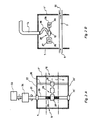
- - la figure 1 représente une vue schématique, en coupe longitudinale, d'un mode de réalisation du dispositif de décalaminage,
- - les figures 2-A et 2-B représentent en détail respectivement en coupe vue de dessus et en coupe latérale, la chambre d'abrasion munie du mécanisme de déplacement de la buse d'injection.
- FIG. 1 represents a schematic view, in longitudinal section, of an embodiment of the descaling device,
- - Figures 2-A and 2-B show in detail respectively in top view and in side section, the abrasion chamber provided with the movement mechanism of the injection nozzle.
Sur les figures, les mêmes éléments sont repérés par des références identiques.In the figures, the same elements are identified by identical references.
Comme on le voit sur la figure 1, le dispositif de décalaminage comporte un boitier métallique 1 qui est divisé successivement en trois enceintes, par rapport au sens de défilement (représenté par une flèche) du produit métallique 2 (ici une brame d'acier), à savoir : un premier compartiment d'aspiration 3, une chambre d'abrasion 4 et un deuxième compartiment d'aspiration 5. Les parois externes 6 et 6' et internes 7 et 7' comportent des ouvertures 8, 9, 10 et 11 en regard les unes des autres de façon à ménager un passage rectiligne du produit 2 à travers le boitier 1.As can be seen in FIG. 1, the descaling device comprises a metal box 1 which is successively divided into three enclosures, relative to the direction of travel (represented by an arrow) of the metal product 2 (here a steel slab) , namely: a
Deux buses 12 et 13 d'injection d'abrasif, que l'on supposera être du sable, sont disposées à la partie supérieure et à la partie inférieure de la chambre de sablage 4 et orientées respectivement vers la grande face supérieure et la grande face inférieure du produit 2.Two
Les buses d'injection 12 et 13 sont reliées à des sources de sable et d'air comprimé non-représentées sur les figures à l'aide des conduits 14 et 15.The
La chambre de sablage 4 est en communication à sa partie inférieure avec un récipient 16 destiné à la récupération par gravité du sable et de la calamine détachée du produit 2.The sanding chamber 4 is in communication at its lower part with a
Comme représentés sur la figure 1, les compartiments d'aspiration 3 et 5 sont connectés à leurs parties supérieures et inférieures à des conduits d'aspiration 17, 18, 19 et 20.As shown in FIG. 1, the
Les parois externes 6 et 6' des compartiments d'aspiration comportent des brosses métalliques 21, 21' et 22, 22'. La densité de ces brosses métalliques est telle que le sable ne peut passer à l'extérieur du boitier 1.The
Suivant un mode de réalisation préféré de l'invention, une paire de brosses métalliques 23 et 23' est fixée à la paroi interne 7' du compartiment d'aspiration 5 de sortie du produit. Chacune des brosses 23 et 23' est en contact avec une grande face à décalaminer du produit 2.According to a preferred embodiment of the invention, a pair of
Deux paires de plaques métalliques, ou volets, 24, 24' et 25, 25' sont disposées dans la chambre de sablage 4. Les volets 24, 24' et 25, 25' sont agencés de façon à racler les faces supérieure et inférieure du produit 2 et par conséquent à pouvoir empêcher le sable de passer dans les compartiments d'aspiration 3 et 5.Two pairs of metal plates, or flaps, 24, 24 'and 25, 25' are arranged in the sanding chamber 4. The
Les figures 2-A et 2-B représentent un système selon lequel le jet de sable balaye toute la largeur du produit.Figures 2-A and 2-B show a system according to which the sandblast sweeps the entire width of the product.
Comme on le voit sur la figure 2-A, la buse d'injection 12 est montée sur un support 26 qui comporte à l'une de ses extrémités un manchon taraudé 27 et à l'autre extrémité un manchon lisse 28. D'autre part, deux tiges, respectivement de travail 29 et de guidage 30, sont disposées parallèlement l'une à l'autre, au travers de la chambre de sablage 4, au-dessus du produit et perpendiculairement à la direction de défilement de célui-ci.As seen in Figure 2-A, the
La tige de travail 29 est animée en rotation par un moteur reversible 33 par l'intermédiaire d'un réducteur 34. Elle repose sur des paliers 31 et 31' qui sont disposés respectivement dans les parois latérales 32 et 32' de la chambre de sablage. Comme on le voit sur la figure 2-A, la partie centrale 35 de la tige 29 est filetée et le manchon taraudé 27 du support est engagé sur cette partie filetée.The working
La tige de guidage 30 est fixée à ses extrémités aux parois latérales 32 et 32' de la chambre de sablage et le support 26 de la buse d'injection est donc monté coulissant sur la tige 30, grâce au manchon lisse 28.The
Comme on le voit sur la figure 2-B, la buse d'injection 12 est reliée au conduit d'aspiration 14 par l'intermédiaire d'un tube souple 36 qui permet le mouvement de son support 26.As can be seen in FIG. 2-B, the
Le fonctionnement du dispositif selon l'invention est le suivant.The operation of the device according to the invention is as follows.
Le produit métallique 2 défile par les ouvertures 8, 9, 10 et 11 à travers les enceintes 3, 4, et 5. Dans la chambre de sablage 4, le sable est injecté par air comprimé aux moyens des buses d'injection 12 et 13 qui effectuent un balayage de la surface du produit selon un mouvement de "va et vient" perpendiculairement à la direction de défilement du produit. Grâce aux chocs mécaniques provoqués par les grains de sable, la calamine se fissure et se détache des faces du produit 2.The
Les volets 24, 24', et 25, 25' contribuent à empêcher le sable injecté et la calamine détachée du produit 2 de passer dans les compartiments d'aspiration 3 et 5. Le sable et la calamine tombent par gravité dans le récipient 16. Les compartiments d'aspiration 3 et 5 sont mis sous aspiration, ce qui évite toute pollution de l'environnement par le sable et les poussières. Les brosses métalliques 21, 21' et 22, 22', en obturant parallèlement les interstices entre les ouvertures 8 et 11 et le produit 2, permettent la mise sous vide des compartiments 3 et 5 avec un faible débit d'aspiration, mais suffisant pour faciliter l'aspiration du sable et des poussières. Les brosses métalliques 22 et 22' ont également pour fonction de nettoyer les faces du produit 2.The
Les brosses métalliques 23 et 23' ont pour fonction, d'une part, d'empêcher le sable de passer dans le compartiment 5 de sortie du produit et, d'autre part, d'éliminer les dernières particules de calamine éventuellement restées collées sur les faces du produit 2.The
Dans le système de balayage représenté sur les figures 2-A et 2-B, la rotation alternative du moteur 33 est transmise par l'intermédiaire du réducteur 34 à la tige de travail 29. Cette rotation alternative de la tige est transformée en un mouvement de translation linéaire de "va-et-vient" du support 26. On peut bien entendu régler la vitesse du mouvement de va-et-vient du support 26 en fonction de la vitesse de défilement du produit de façon à pouvoir balayer correctement toute la largeur de la face du produit par le jet de sable. Ceci reste toutefois possible, bien entendu, dans la mesure où la vitesse du produit demeure relativement modérée, par exemple de l'ordre de 1 m/mn, comme c'est le cas des brames à l'entrée d'un laminoir planétaire, en particulier.In the scanning system represented in FIGS. 2-A and 2-B, the alternating rotation of the
Dans cet exemple, le système de balayage par le jet de sable n'a été considéré que pour la partie supérieure de la chambre de sablage 4. Mais, bien entendu, un deuxième système identique est disposé dans la partie inférieure de la chambre de sablage 4, pour effectuer le balayage de la face inférieure du produit 2.In this example, the sandblasting system was only considered for the upper part of the sandblasting chamber 4. However, of course, a second identical system is placed in the lower part of the sandblasting chamber. 4, to scan the underside of
Il va de soi que la description donnée ci-dessus n'a aucun caractère limitatif et que diverses modifications pourraient être apportées sans sortir de la portée de l'invention définie dans les revendications annexées.It goes without saying that the description given above has no limiting character and that various modifications could be made without departing from the scope of the invention defined in the appended claims.
En particulier, la mobilité de la buse d'injection pour le balayage du produit peut se faire autrement que par un mouvement de translation en "va et vient" et notamment par pivotement alternatif de la buse autour d'un axe fixe, parallèle à la direction du produit, à partir d'un mécanisme très simple à bielle et excentrique à la portée de tout homme de métier.In particular, the mobility of the injection nozzle for sweeping the product can be done other than by a translational movement in "back and forth" and in particular by alternating pivoting of the nozzle around a fixed axis, parallel to the direction of the product, from a very simple eccentric and connecting rod mechanism within the reach of any skilled person.
Claims (8)
Applications Claiming Priority (2)
| Application Number | Priority Date | Filing Date | Title |
|---|---|---|---|
| FR8118662A FR2513924B1 (en) | 1981-10-01 | 1981-10-01 | DEVICE FOR DECALAMINATING METALLURGICAL PRODUCTS |
| FR8118662 | 1981-10-01 |
Publications (1)
| Publication Number | Publication Date |
|---|---|
| EP0077234A1 true EP0077234A1 (en) | 1983-04-20 |
Family
ID=9262718
Family Applications (1)
| Application Number | Title | Priority Date | Filing Date |
|---|---|---|---|
| EP82401736A Withdrawn EP0077234A1 (en) | 1981-10-01 | 1982-09-27 | Device for dry de-scaling of travelling metallurgical products |
Country Status (4)
| Country | Link |
|---|---|
| EP (1) | EP0077234A1 (en) |
| JP (1) | JPS58132313A (en) |
| BR (1) | BR8205748A (en) |
| FR (1) | FR2513924B1 (en) |
Cited By (1)
| Publication number | Priority date | Publication date | Assignee | Title |
|---|---|---|---|---|
| DE29502234U1 (en) * | 1995-02-11 | 1995-04-13 | Ernst Peiniger GmbH Unternehmen für Bautenschutz, 45145 Essen | Surface processing device for elongated, stationary bodies, in particular for suspension cables on bridges |
Citations (6)
| Publication number | Priority date | Publication date | Assignee | Title |
|---|---|---|---|---|
| US1544519A (en) * | 1919-09-26 | 1925-06-30 | Willys Overland Co | Sand-blast equipment |
| US1842619A (en) * | 1927-10-24 | 1932-01-26 | Blaw Knox Co | Sheet cleaning apparatus |
| US1884791A (en) * | 1927-06-06 | 1932-10-25 | Blaw Knox Co | Scale removing apparatus |
| US2037047A (en) * | 1932-06-28 | 1936-04-14 | Pangborn Corp | Blast cleaning machine |
| US2621446A (en) * | 1952-04-16 | 1952-12-16 | Hydraulic Supply Mfg Company | Grit blasting device for cleaning pipes and the like |
| US3031802A (en) * | 1960-11-29 | 1962-05-01 | Bell Intercontinental Corp | Blast machine sealing means |
-
1981
- 1981-10-01 FR FR8118662A patent/FR2513924B1/en not_active Expired
-
1982
- 1982-09-27 EP EP82401736A patent/EP0077234A1/en not_active Withdrawn
- 1982-09-30 BR BR8205748A patent/BR8205748A/en unknown
- 1982-10-01 JP JP17314182A patent/JPS58132313A/en active Pending
Patent Citations (6)
| Publication number | Priority date | Publication date | Assignee | Title |
|---|---|---|---|---|
| US1544519A (en) * | 1919-09-26 | 1925-06-30 | Willys Overland Co | Sand-blast equipment |
| US1884791A (en) * | 1927-06-06 | 1932-10-25 | Blaw Knox Co | Scale removing apparatus |
| US1842619A (en) * | 1927-10-24 | 1932-01-26 | Blaw Knox Co | Sheet cleaning apparatus |
| US2037047A (en) * | 1932-06-28 | 1936-04-14 | Pangborn Corp | Blast cleaning machine |
| US2621446A (en) * | 1952-04-16 | 1952-12-16 | Hydraulic Supply Mfg Company | Grit blasting device for cleaning pipes and the like |
| US3031802A (en) * | 1960-11-29 | 1962-05-01 | Bell Intercontinental Corp | Blast machine sealing means |
Cited By (1)
| Publication number | Priority date | Publication date | Assignee | Title |
|---|---|---|---|---|
| DE29502234U1 (en) * | 1995-02-11 | 1995-04-13 | Ernst Peiniger GmbH Unternehmen für Bautenschutz, 45145 Essen | Surface processing device for elongated, stationary bodies, in particular for suspension cables on bridges |
Also Published As
| Publication number | Publication date |
|---|---|
| BR8205748A (en) | 1983-09-06 |
| FR2513924B1 (en) | 1985-05-31 |
| FR2513924A1 (en) | 1983-04-08 |
| JPS58132313A (en) | 1983-08-06 |
Similar Documents
| Publication | Publication Date | Title |
|---|---|---|
| EP0521794B1 (en) | Apparatus for storing and conveying ice-balls, without sticking to each other, from their place of production to their place of use, where they are propelled against a target | |
| EP0215015B1 (en) | Plant for projecting particles of carbon dioxide ice | |
| FR3002866A1 (en) | DESAMIANTING DEVICE AND METHOD | |
| CA3096092A1 (en) | Automatic machine for sorting or inspecting a flow of objects, equipped with a cleaning device | |
| EP0384873B1 (en) | Apparatus for cleaning building-walls | |
| FR2864796A1 (en) | Device for cleaning a horizontal roller, carried by and rotated by the roller, notably for cleaning the rollers of glass conveyors without interrupting normal operation | |
| CN101218045B (en) | Device for continuous surface cleaning of rotatable casting rolls of a continuous strip caster | |
| FR3036635A1 (en) | PROCESS FOR TREATING DUST REMOVED FROM A SURFACE BY A TOOL AND EQUIPMENT FOR CARRYING OUT SAID METHOD | |
| EP0077234A1 (en) | Device for dry de-scaling of travelling metallurgical products | |
| EP0457669B1 (en) | Device for remote-sanitising of a surface in a hostile environment by degradation with recuperation and treatment of the wastes | |
| JP3889237B2 (en) | Deposit removal device | |
| US1062248A (en) | Suction-hood for abrading-tools. | |
| FR2494160A1 (en) | Abrasive surface treatment for polishing vehicle - forms ice crystals projected onto work in cold air stream | |
| BE1011879A3 (en) | Process cleaning projection particle and apparatus for implementing the method. | |
| FR2667087A1 (en) | Device for scouring and cleaning the ground | |
| FR2591520A1 (en) | METHOD AND APPARATUS FOR MECHANICAL PROCESSING OF PARTS | |
| EP3000536B1 (en) | Device for cleaning a screen | |
| FR2680163A1 (en) | Device for cleaning belt conveyors | |
| FR2750898A1 (en) | Decontamination of surfaces using high pressure liquid | |
| FR2551908A1 (en) | METHOD AND DEVICE FOR DECONTAMINATING METAL PROFILES SOILED BY RADIOACTIVITY | |
| FR2565090A1 (en) | NOZZLE | |
| EP2497601B1 (en) | System for treating an inner surface of a conduit by spraying particles | |
| EP0035420B1 (en) | Device of cleaning panel heat exchangers | |
| CN221435298U (en) | Fiber welding machine removes incomplete material subassembly | |
| SU923352A3 (en) | Method for liquid cleaning of metal strip |
Legal Events
| Date | Code | Title | Description |
|---|---|---|---|
| PUAI | Public reference made under article 153(3) epc to a published international application that has entered the european phase |
Free format text: ORIGINAL CODE: 0009012 |
|
| AK | Designated contracting states |
Designated state(s): AT BE DE GB IT LU NL SE |
|
| 17P | Request for examination filed |
Effective date: 19831014 |
|
| STAA | Information on the status of an ep patent application or granted ep patent |
Free format text: STATUS: THE APPLICATION IS DEEMED TO BE WITHDRAWN |
|
| 18D | Application deemed to be withdrawn |
Effective date: 19851121 |
|
| RIN1 | Information on inventor provided before grant (corrected) |
Inventor name: RATTE, PATRICE Inventor name: MICHELET, JACQUES |