EP0077245A1 - Manipulator for remote intervention in a water collector of a steam generator - Google Patents
Manipulator for remote intervention in a water collector of a steam generator Download PDFInfo
- Publication number
- EP0077245A1 EP0077245A1 EP82401782A EP82401782A EP0077245A1 EP 0077245 A1 EP0077245 A1 EP 0077245A1 EP 82401782 A EP82401782 A EP 82401782A EP 82401782 A EP82401782 A EP 82401782A EP 0077245 A1 EP0077245 A1 EP 0077245A1
- Authority
- EP
- European Patent Office
- Prior art keywords
- arm
- clamps
- plate
- tube plate
- carrier block
- Prior art date
- Legal status (The legal status is an assumption and is not a legal conclusion. Google has not performed a legal analysis and makes no representation as to the accuracy of the status listed.)
- Granted
Links
- XLYOFNOQVPJJNP-UHFFFAOYSA-N water Substances O XLYOFNOQVPJJNP-UHFFFAOYSA-N 0.000 title claims abstract description 18
- 238000006073 displacement reaction Methods 0.000 description 3
- 230000002285 radioactive effect Effects 0.000 description 3
- 230000002950 deficient Effects 0.000 description 2
- 238000009434 installation Methods 0.000 description 2
- 238000012423 maintenance Methods 0.000 description 2
- 238000003466 welding Methods 0.000 description 2
- 230000009193 crawling Effects 0.000 description 1
- 238000005192 partition Methods 0.000 description 1
- 230000000737 periodic effect Effects 0.000 description 1
- 230000003252 repetitive effect Effects 0.000 description 1
- 239000000523 sample Substances 0.000 description 1
- 238000007789 sealing Methods 0.000 description 1
- 239000000725 suspension Substances 0.000 description 1
- 230000009897 systematic effect Effects 0.000 description 1
- 238000012795 verification Methods 0.000 description 1
Images

Classifications
-
- B—PERFORMING OPERATIONS; TRANSPORTING
- B25—HAND TOOLS; PORTABLE POWER-DRIVEN TOOLS; MANIPULATORS
- B25J—MANIPULATORS; CHAMBERS PROVIDED WITH MANIPULATION DEVICES
- B25J5/00—Manipulators mounted on wheels or on carriages
-
- F—MECHANICAL ENGINEERING; LIGHTING; HEATING; WEAPONS; BLASTING
- F22—STEAM GENERATION
- F22B—METHODS OF STEAM GENERATION; STEAM BOILERS
- F22B37/00—Component parts or details of steam boilers
- F22B37/002—Component parts or details of steam boilers specially adapted for nuclear steam generators, e.g. maintenance, repairing or inspecting equipment not otherwise provided for
- F22B37/003—Maintenance, repairing or inspecting equipment positioned in or via the headers
- F22B37/005—Positioning apparatus specially adapted therefor
Definitions
- the present invention relates to a remote manipulator more particularly intended to support and move the tools necessary for interventions inside a water box of a steam generator in a pressurized water nuclear power plant.
- the very large number of tubes in the tubular bundles of steam generators must be subject to periodic verification and maintenance operations, such as, for example, welding operations, fitting plugs. obturation to neutralize defective tubes, or interventions on the inner lining of the tubes.
- maintenance operations must be carried out from the water box, that is to say in a highly radioactive field; it is therefore necessary to use remote-controlled devices to limit human intervention to the simple installation of equipment.
- the steam generators are generally with vertical tubes, that is to say that the tube plate is then "at the ceiling" of the water box.
- each movement has phases during which the tool holder remains suspended from only two pliers, which greatly limits the weight of the tools that can be used.
- the present invention makes it possible to have a tele-manipulator device, both of greater capacity and more efficient, while reducing the interventions of personnel in a radioactive environment.
- the invention therefore relates to an intervention remote manipulator in a steam generator water box, intended to be fixed under the tubular plate of the generator, the device being of the type comprising expandable clamps for engaging and block on demand in holes in the tube plate, mounted on arms carried by a support block, with means for independently giving each arm, on the one hand, movements perpendicular to the plate to engage clamps in the holes or release them, and secondly stepwise movements parallel to the plate, thus allowing the autonomous movement of the device under the tubular plate while still hanging there by at least two clamps.
- the carrier block supports four independent arms each provided with two expandable clamps, and at its part opposite to the tubular plate, the carrier block supports an arm with several elements articulated between them, the extreme element of the arm being provided with means for fixing tools, and the whole of the arm itself being orientable around the axis of the block perpendicular to the tube plate;
- the device comprises remote-controlled means for adjusting and maintaining the angular position of the arm relative to the carrier block, and the relative angular position between them of each of the elements of the arm.
- the carrier block is constituted by a tubular frame with guide bars regularly distributed in groups of 2 around its axis, each arm being constituted by a carriage engaged on each. pair of bars, the clamps themselves being carried by a slide movable on the carriage perpendicular to the guide bars.
- the apparatus comprises a support block generally designated by 1, and provided with attachment clips 10 and means for moving these clips to ensure the movement of the device under the tube plate.
- Block 1 supports a mani- ? articulated ulator 2 which constitutes the actual tool holder.
- the carrier block 1, more visible in Figures 2 and 3, is here constituted by a tubular frame 5 carrying at its ends two annular flanges 6 and 7.
- the flanges 6 and 7 are also connected by eight guide bars 8-9 regularly distributed in groups of two around the frame 5.
- the device is provided with eight expandable clamps 10, of the usual type and with positive security, that is to say that their expandable end is normally in the expanded position, therefore in the position clamping and hooking when it is engaged in one of the holes in the plate. It is by the controlled action of the built-in cylinder, pneumatic or electric, that the expandable part can be retracted to unhook the clamp; in case loss of pneumatic or electrical power, the device will therefore remain attached to the plate.
- a more complete description of such expandable clamps can be found in the French patent already cited 2,309,314.
- the block 1 comprises four identical sets, or arms, as shown in FIGS. 2 and 3. Each arm therefore carries two clamps 10 and is associated with a pair of bars 8-9.
- the arm comprises a sliding carriage 12 which can be moved along the bars 8-9, that is to say perpendicular to the tube plate when the device is in place.
- the slide 12 is simply engaged on the bar 8 which has only a guiding role.
- the bar 9 constitutes the rod on either side of a fixed piston 13o which slides in relative movement in a bore 14 of the slide 12.
- the bore 14 is closed at each end by a bottom 15, crossed by the bar 9, so that a double-acting cylinder with fixed piston has thus been formed, and the movable body of which is the slide 12 itself.
- the connections 16 allow the supply of one or the other chamber of the jack, and consequently the parallel movement of the slide along the bars 8 and 9.
- the two clamps 10 are fixed to the ends of a cross-member 18 which slides in a slide 19 formed on the front face of the slide 12, by the free space between two plates 20-21 secured to the slide 12.
- the cross-member 18 is held trapped in the slide 19 by the two supports 22 fixed on the plates 20, 21 and which span the crosspiece 18 without hindering its transverse movement.
- Each support 22 also forms one of the two bottoms of a double-acting cylinder, the body 24 of which contains a piston with two rods 25, 26 which pass through the supports 22.
- the total length of the assembly of the piston and of its rods 25- 26 is equal to the internal distance between the supports 27 of the clamps 10, so that the ends of the rods 25 and 26 are always in contact with the two supports 27.
- the connections 29 allow the supply of one or the other chamber of the actuator 24, which causes the transverse displacement of the assembly of the cross member 18 and of the two clamps 10 that it supports.
- the total stroke of the actuator 24 is equal to a pitch for installing the tubes on the tube plate, while of course the distance between the two clamps 10 is equal to an integer multiple of this pitch.
- the lower flange 7 supports a rotary crown 32 under which the assembly of the tool-carrying arm 2 pivots around the axis of the tubular frame 5.
- the arm 2 comprises a first element 33 forming a fork offset relative to the axis of rotation of the crown 32.
- a second element 34 is articulated at 35 out of 33.
- a third element 36 is similarly articulated at 37 on the other end of 34.
- a tool-carrying slide 38 is articulated at 39 at the other end of 36.
- the slide 38 is equipped with usual means for gripping and holding tools, means which are here (FIG. 1) simply symbolized by a groove 40.
- the axes of the articulations 35, 37 and 39 are mutually parallel and perpendicular to the axis of the frame 5.
- Each articulation, as well the articulations 35, 37 and 39 as that of the yoke 33 on the crown 32, is equipped with an internal angular positioning motor allowing, by a usual master-slave system, each element of the arm 2 to reproduce by remote control the displacements of the homologous elements of an arm maneuvered on a replica by an external operator.
- the sheath 42 groups all the circuits of this remote control.
- the device is particularly suitable for repetitive operations, such as the systematic sealing of tubes in a defective area. It is then possible, by means of the manipulator arm 2 to take the plugs one after the other through the hole 44 after having placed the previous one, and without having to move the carrier block 1 between each operation.
Landscapes
- Engineering & Computer Science (AREA)
- Physics & Mathematics (AREA)
- Mechanical Engineering (AREA)
- High Energy & Nuclear Physics (AREA)
- Thermal Sciences (AREA)
- General Engineering & Computer Science (AREA)
- Robotics (AREA)
- Manipulator (AREA)
- Monitoring And Testing Of Nuclear Reactors (AREA)
- Apparatus Associated With Microorganisms And Enzymes (AREA)
Abstract
L'invention a pour objet un télémanipulateur d'intervention dans une boîte à eau de générateur de vapeur, et destiné à venir se fixer sous la plaque tubulaire du générateur, du type comportant des pinces expansibles (10) montées sur des bras portés par un bloc porteur (1) pour s'engager et se bloquer à la demande dans des orifices de la plaque tubulaire, avec des moyens permettant le déplacement autonome de l'appareil sous la plaque tubulaire en y restant toujours suspendu par au moins deux pinces. Selon l'invention, le bloc porteur est muni de quatre bras indépendants munis chacun de deux pinces expansibles, et, à sa partie opposée à la plaque tubulaire, il supporte un bras (2) a plusieurs éléments (33, 34, 36) articulés entre eux, l'élément extrême du bras étant muni de moyens de fixation d'outils (38); l'ensemble du bras étant lui-même orientable autour de l'axe du bloc perpendiculaire à la plaque tubulaire, avec des moyens télécommandés pour régler et maintenir la position angulaire du bras par rapport au bloc porteur et la position angulaire relative entre eux de chacun des éléments du bras. L'invention s'applique spécialement aux générateurs de vapeur de centrales nucléaires.The subject of the invention is a remote manipulator for intervention in a steam generator water box, and intended to be fixed under the tubular plate of the generator, of the type comprising expandable clamps (10) mounted on arms carried by a carrier block (1) for engaging and locking on demand in the orifices of the tube plate, with means allowing the autonomous movement of the device under the tube plate while still hanging there by at least two clamps. According to the invention, the carrier block is provided with four independent arms each provided with two expandable clamps, and, at its part opposite the tubular plate, it supports an arm (2) with several articulated elements (33, 34, 36) between them, the end element of the arm being provided with means for fixing tools (38); the whole arm being itself orientable around the axis of the block perpendicular to the tube plate, with remote-controlled means for adjusting and maintaining the angular position of the arm relative to the carrier block and the relative angular position between them of each elements of the arm. The invention applies especially to steam generators in nuclear power plants.
Description
La présente invention concerne un télé-manipulateur plus particulièrement destiné à supporter et à déplacer les outils nécessaires à des interventions à l'intérieur d'une boite à eau d'un générateur de vapeur dans une centrale nucléaire à eau pressurisée.The present invention relates to a remote manipulator more particularly intended to support and move the tools necessary for interventions inside a water box of a steam generator in a pressurized water nuclear power plant.
Dans une centrale nucléaire à eau pressurisée, les très nombreux tubes des faisceaux tubulaires des générateurs de vapeur doivent faire l'objet d'opérations périodiques de vérification et de maintenance, comme par exemple des opérations de soudage, de mise en place de bouchons d'obturation pour neutraliser des tubes défectueux, ou d'interventions sur le revêtement intérieur des tubes. Ces opérations de maintenance doivent se faire à partir de la boite à eau, c'est à dire en domaine fortement radio-actif ; il est donc nécessaire d'utiliser des appareils télécommandés pour limiter les interventions humaines à la simple mise en place du matériel. En outre les générateurs de vapeur sont généralement à tubes verticaux, c'est à dire que la plaque tubulaire est alors "au plafond" de la boite à eau.In a pressurized water nuclear power plant, the very large number of tubes in the tubular bundles of steam generators must be subject to periodic verification and maintenance operations, such as, for example, welding operations, fitting plugs. obturation to neutralize defective tubes, or interventions on the inner lining of the tubes. These maintenance operations must be carried out from the water box, that is to say in a highly radioactive field; it is therefore necessary to use remote-controlled devices to limit human intervention to the simple installation of equipment. In addition, the steam generators are generally with vertical tubes, that is to say that the tube plate is then "at the ceiling" of the water box.
On peut également être amené à devoir intervenir sur les parois internes de la boite à eau, par exemple pour vérifier leur état de surface.It may also be necessary to intervene on the internal walls of the water box, for example to check their surface condition.
On a déjà réalisé des appareils capables d'être déplacés par télécommande sous la plaque tubulaire d'un générateur de vapeur. Les brevets français publiés sous les numéros 2.309.314 ou 2.457.741 décrivent de tels appareils comportant deux bras perpendiculaires munis chacun, à chacune de ses extrémités, d'une pince expansible pouvant s'engager dans les orifices de la plaque tubulaire. Par des jeux de chariots et de vérins on peut donner indépendamment à chaque bras des mouvements perpendiculaires à la plaque pour engager les pinces dans les orifices ou les en dégager, et des mouvements pas à pas parallèles à la plaque, permettant ainsi le déplacement autonome de l'appareil par "reptation" sous la plaque. Pendant les mouvements l'appareil reste toujours suspendu par au moins deux pinces, et par quatre pinces en position de travail.We have already made devices capable of being moved by remote control under the tube plate of a steam generator. French patents published under the numbers 2.309.314 or 2.457.741 describe such devices comprising two perpendicular arms each provided at each of its ends with an expandable clamp which can engage in the orifices of the tube plate. By sets of carriages and jacks it is possible to independently give each arm movements perpendicular to the plate to engage the pliers in the openings or to disengage them, and stepwise movements parallel to the plate, thus allowing the autonomous movement of the device by "crawling" under the plate. During movements the device always remains suspended by at least two clamps, and by four clamps in the working position.
De tels appareils présentent cependant l'inconvénient d'un encombrement général assez important. Mais surtout, lorsqu'un appareil est en position de travail suspendu à ses quatre pinces, il ne permet d'opérer que sur un nombre très limité d'orifices de la plaque. Dans la version du brevet 2.309.314, prévu simplement pour des guides de sondes de contrôle, seuls quatre tubes sont accessibles ; dans la version du brevet 2.457.741, qui permet d'utiliser des outils plus complexes comme des têtes de soudage par exemple, un seul orifice de la plaque est dans le champ d'action de l'outil qui ne peut se déplacer que dans un dièdre laissé libre par les bras supports. Ceci est assez gênant chaque fois qu'il faut effectuer la même opération sur une série d'orifices dans la même zone de la plaque, car pour chaque changement d'orifice il faut alors déplacer le porte-outil, c'est à dire dégager un bras, le déplacer d'un pas, et l'engager à nouveau dans la plaque, et répéter les trois opérations sur l'autre bras, si. bien que la durée des temps de déplacement, qui sont des temps morts, vient à dépasser les temps efficaces d'intervention.However, such devices have the disadvantage of a fairly large overall size. But above all, when a device is in the working position suspended from its four clamps, it allows operation only on a very limited number of orifices in the plate. In the version of patent 2,309,314, intended simply for guides of control probes, only four tubes are accessible; in patent version 2,457,741, which allows the use of more complex tools such as welding heads for example, a single orifice in the plate is within the field of action of the tool which can only move in a dihedral left free by the support arms. This is quite annoying each time it is necessary to carry out the same operation on a series of orifices in the same zone of the plate, because for each change of orifice it is then necessary to move the tool holder, that is to say release one arm, move it one step, and engage it again in the plate, and repeat the three operations on the other arm, if. although the duration of travel time, which is dead time, comes to exceed the effective intervention time.
Par ailleurs chaque mouvement comporte des phases durant lesquelles le porte-outil reste suspendu à seulement deux pinces, ce qui limite beaucoup le poids des outils utilisables.Furthermore, each movement has phases during which the tool holder remains suspended from only two pliers, which greatly limits the weight of the tools that can be used.
On notera encore que ces appareils ne permettent de travailler que sous la plaque tubulaire elle-même, alors que des interventions peuvent aussi être nécessaires sur les parois intérieures de la boite à eau.It will also be noted that these devices allow work only under the tube plate itself, while interventions may also be necessary on the interior walls of the water box.
Enfin, bien que par exemple sur l'appareil décrit au brevet 2.457.741 on-ait pu prévoir une petite tourelle pour recevoir en attente des outils différents, ceci n'est pratiquement possible que pour de petits outils en raison de la charge limite supportable par deux pinces ; en pratique il se révèle fréquemment nécessaire de changer les outils sur le porte-outil, ce qui oblige à multiplier les entrées dans la boite à eau c'est à dire en une zone fortement radio-active.Finally, although for example on the apparatus described in patent 2,457,741, a small turret could have been provided to receive different tools on standby, this is practically only possible for small tools because of the bearable load limit by two clamps; in practice, it frequently proves necessary to change the tools on the tool holder, which means increasing the number of entries in the water box, that is to say in a highly radioactive area.
La présente invention permet de disposer d'un appareil télé-manipulateur, à la fois de plus grande capacité et plus performant, tout en réduisant les interventions du personnel en milieu radio-actif.The present invention makes it possible to have a tele-manipulator device, both of greater capacity and more efficient, while reducing the interventions of personnel in a radioactive environment.
L'invention concerne donc un télé-manipulateur d'intervention dans une boite à eau de générateur de vapeur, destiné à venir se fixer sous la plaque tubulaire du générateur, l'appareil étant du type comportant des pinces expansibles pour s'engager et se bloquer à la demande dans des orifices de la plaque tubulaire, montées sur des bras portés par un bloc porteur, avec des moyens pour donner indépendamment à chaque bras, d'une part des mouvements perpendiculaires à la plaque pour engager des pinces dans les orifices ou les en dégager, et d'autre part des mouvements pas à pas parallèles à la plaque, permettant ainsi le déplacement autonome de l'appareil sous la plaque tubulaire en y restant toujours suspendu par au moins deux pinces.The invention therefore relates to an intervention remote manipulator in a steam generator water box, intended to be fixed under the tubular plate of the generator, the device being of the type comprising expandable clamps for engaging and block on demand in holes in the tube plate, mounted on arms carried by a support block, with means for independently giving each arm, on the one hand, movements perpendicular to the plate to engage clamps in the holes or release them, and secondly stepwise movements parallel to the plate, thus allowing the autonomous movement of the device under the tubular plate while still hanging there by at least two clamps.
Selon l'invention le bloc porteur supporte quatre bras indépendants munis chacun de deux pinces expansibles, et à sa partie opposée à la plaque tubulaire le bloc porteur supporte un bras à plusieurs éléments articulés entre eux, l'élément extrême du bras étant muni de moyens de fixation d'outils, et l'ensemble du bras étant lui-même orientable autour de l'axe du bloc perpendiculaire à la plaque tubulaire ; l'appareil comporte des moyens télécommandés pour régler et maintenir la position angulaire du bras par rapport au bloc porteur, et la position angulaire relative entre eux de chacun des éléments du bras.According to the invention the carrier block supports four independent arms each provided with two expandable clamps, and at its part opposite to the tubular plate, the carrier block supports an arm with several elements articulated between them, the extreme element of the arm being provided with means for fixing tools, and the whole of the arm itself being orientable around the axis of the block perpendicular to the tube plate; the device comprises remote-controlled means for adjusting and maintaining the angular position of the arm relative to the carrier block, and the relative angular position between them of each of the elements of the arm.
Selon une forme particulière de réalisation de l'invention, le bloc porteur est constitué par un bâti tubulaire avec des barres guides régulièrement réparties par groupes de 2 autour de son axe, chaque bras étant constitué par un chariot engagé sur chaque. paire de barres, les pinces étant elles-mêmes portées par un coulisseau déplaçable sur le chariot perpendiculairement aux barres guides.According to a particular embodiment of the invention, the carrier block is constituted by a tubular frame with guide bars regularly distributed in groups of 2 around its axis, each arm being constituted by a carriage engaged on each. pair of bars, the clamps themselves being carried by a slide movable on the carriage perpendicular to the guide bars.
L'invention sera mieux comprise en se référant à un mode de réalisation particulier donné à titre d'exemple et représenté par les dessins annexés.
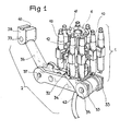
- La figure 1 est une vue en perspective de l'ensemble de l'appareil isolé.
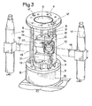
- La figure 2, sur laquelle nn n'a représenté qu'un seul bras de fixation, donne le détail du montage de ce.bras, mobile sur son chariot de déplacement perpendiculairement à la plaque.
- La figure 3 montre les moyens utilisés pour le déplacement du chariot.
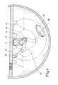
- La figure 4 montre le champ d'action de l'appareil dans l'ensemble de la boite à eau, à partir d'une position fixe sous la plaque tubulaire.
- Figure 1 is a perspective view of the entire isolated device.
- Figure 2, in which nn has shown only one fixing arm, gives the detail of the mounting of ce.bras, mobile on its displacement carriage perpendicular to the plate.
- Figure 3 shows the means used for moving the carriage.
- Figure 4 shows the field of action of the device in the entire water box, from a fixed position under the tube plate.
En se référant tout d'abord à la figure 1, on verra que l'appareil comporte un bloc porteur globalement désigné par 1, et muni de pinces d'accrochage 10 et de moyens de déplacement de ces pinces pour assurer le déplacement de l'appareil sous la plaque tubulaire. Le bloc 1 soutient un mani- ?ulateur articulé 2 qui constitue le porte-outil proprement dit.By first referring to FIG. 1, it will be seen that the apparatus comprises a support block generally designated by 1, and provided with
Le bloc porteur 1, plus visible sur les figures 2 et 3, est ici constitué par un bâti tubulaire 5 portant à ses extrémités deux flasques annulaires 6 et 7. Les flasques 6 et 7 sont également reliés par huit barres de guidage 8-9 régulièrement réparties par groupes de deux autour du bâti 5. L'appareil est muni de huit pinces expansibles d'accrochage 10, de type usuel et à sécurité positive, c'est à dire que leur extrémité expansible est normalement en position expansée, donc en position de serrage et d'accrochage lorsqu'elle est engagée dans un des orifices de la plaque. C'est par l'action commandée du vérin incorporé, pneumatique ou électrique, que la partie expansible peut Être rétractée pour décrocher la pince ; en cas de perte d'alimentation pneumatique ou électrique l'appareil restera donc accroché à la plaque. Une description plus complète de telles pinces expansibles pourra êtretrouvée dans le brevet français déjà cité 2.309.314.The
Le bloc 1 comporte quatre ensembles, ou bras, identiques tels que représentés aux figures 2 et 3. Chaque bras porte donc deux pinces 10 et est associé à une paire de barres 8-9.The
Le bras comporte un chariot coulissant 12 qui peut être déplacé le long des barres 8-9, c'est à dire perpendiculairement à la plaque tubulaire lorsque l'appareil est en place. Le coulisseau 12 est simplement engagé sur la barre 8 qui n'a qu'un rôle de guidage. Par contre la barre 9 constitue la tige de part et d'autre d'un piston fixe 13o qui coulisse en mouvement relatif dans un alésage 14 du coulisseau 12. L'alésage 14 est fermé à chaque extrémité par un fond 15, traversé par la barre 9, de sorte que l'on a ainsi constitué un vérin à double effeqà piston fixe, et dont le corps mobile est le coulisseau 12 lui-même. Les raccords 16 permettent l'alimentation de l'une ou l'autre chambre du vérin, et par conséquent le déplacement parallèle du coulisseau le long des barres 8 et 9.The arm comprises a
Les deux pinces 10 sont fixées aux extrémités d'une traverse entretoise 18 qui coulisse dans une glissière 19 formée sur la face avant du coulisseau 12, par l'espace libre entre deux plaques 20-21 solidaires du coulisseau 12. La traverse 18 est maintenue prisonnière dans la glissière 19 par les deux supports 22 fixés sur les plaques 20, 21 et qui enjambent la traverse 18 sans gêner son déplacement transversal..The two
Chaque support 22 forme également un des deux fonds d'un vérin à double effet dont le corps 24 renferme un piston à deux tiges 25, 26 qui traversent les supports 22. La longueur totale de l'ensemble du piston et de ses tiges 25-26 est égale à la distance intérieure entre les supports 27 des pinces 10, de sorte que les extrémités des tiges 25 et 26 sont toujours au contact des deux supports 27. Les raccords 29 permettent l'alimentation de l'une ou l'autre chambre du vérin 24, ce qui entraine le déplacement transversal de l'ensemble de la traverse 18 et des deux pinces 10 qu' elle supporte. La course totale du vérin 24 est égale à un pas d'implantation des tubes sur la plaque tubulaire, tandis que bien entendu l'entraxe entre les deux pinces 10 est égal à un multiple entier de ce pas.Each
Le flasque inférieur 7 supporte une couronne rotative 32 sous laquelle pivote l'ensemble du bras porte outil 2, autour de l'axe du bâti tubulaire 5. Le bras 2 comporte un premier élément 33 formant une chape déportée par rapport à l'axe de rotation de la couronne 32. Un deuxième élément 34 est articulé en 35 sur 33. Un troisième élément 36 est de la même façon articulé en 37 sur l'autre extrémité de 34. Enfin un coulisseau porte-outil 38 est articulé en 39 à l'autre extrémité de 36. Le coulisseau 38 est équipé de moyens usuels de saisie et de maintien d'outils, moyens qui sont ici (figure 1) simplement symbolisés par une rainure 40.The
Les axes des articulations 35, 37 et 39 sont parallèles entre eux et perpendiculaires à l'axe du bâti 5. Chaque articulation, aussi bien les articulations 35, 37 et 39 que celle de la chape 33 sur la couronne 32, est équipée d'un moteur interne de positionnement angulaire permettant, par un système usuel maitre-esclave, à chaque élément du bras 2 de reproduire par télécommande les déplacements des éléments homologues d'un bras manoeuvré sur une réplique par un opérateur extérieur. La gaine 42 regroupe tous les circuits de cette télécommande.The axes of the
On voit qu'on a ainsi réalisé un appareil particulièrement compact, grâce en particulier au vérin interne pour le déplacement de chaque coulisseau 12. Malgré la présence de huit pinces d'accrochage, qui permettent de supporter une lourde charge d'outils, l'appareil passe quand même sans difficulté par le trou d'homme d'accès à l'intérieur de la boite à eau. Bien entendu, lors de l'introduction de l'appareil dans la boite à eau le bras articulé est déployé, si bien que l'encombrement maximal transversal de l'ensemble est l'encombrement diamétral sur les pinces 10, encombrement inférieur au diamètre du trou d'homme.It can be seen that a particularly compact device has thus been produced, thanks in particular to the internal jack for the movement of each
La mise en place de l'appareil en suspension sous la plaque tubulaire se fait de la même façon que pour les appareils antérieurs, avec centrage par les pions 41 du flasque supérieur qui viennent s'engager dans deux orifices de la plaque, puis engagement de l'ensemble des huit pinces dans d'autres orifices pour assurer l'accrochage à la plaque.The installation of the device in suspension under the tube plate is done in the same way as for the previous devices, with centering by the
Lorsque l'appareil est en place sous la plaque tubulaire 43, on'.voit sur la figure 4 l'importance de la zone accessible pour le porte outil 38 sans avoir à déplacer l'appareil, et simplement en faisant varier l'orientation relative des éléments 34 et 36 et l'orientation de la chape 33 par rapport à la couronne 32. La zone balayable par le porte outil 38 représente ici près de la moitié de la surface de la plaque tubulaire. Mais en outre le porte outil 38 peut également être amené au voisinage de toute une partie des parois internes de la boite à eau, qu'il s'agisse de la partie sphérique ou bien de la surface plane de la cloison de séparation entre la boite à eau chaude et la boite à eau froide. Le porte outil 38 peut aussi être amené jusqu'au trou d'homme 44 pour recevoir un nouvel outil.When the device is in place under the
Bien entendu si l'on veut ensuite déplacer l'appareil vers un autre emplacement de la plaque tubulaire on procèdera comme avec les appareils antérieurs, en dégageant deux groupes de pinces opposés,: en les déplaçant d'un pas dans le même sens pour les engager dans quatre orifices différents, puis on déplacera le bâti en mouvement relatif après avoir dégagé les quatre autres pinces qui seront ensuite elles aussi engagées à nouveau dans des orifices différents. On pourra noter que dans une telle manoeuvre l'appareil reste toujours suspendu à un minimum de quatre pinces, ce qui double sa capacité de charge par rapport aux appareils antérieurs.Of course if we then want to move the device to another location on the tube plate we will proceed as with the previous devices, by releasing two groups of opposite clamps: by moving them one step in the same direction for the engage in four different holes, then move the frame in relative motion after having released the other four clamps which will then also be engaged again in different holes. It will be noted that in such an operation the device always remains suspended from a minimum of four clamps, which doubles its load capacity compared to the previous devices.
L'appareil se prête particulièrement bien à des opérations répétitives, comme par exemple l'obturation systématique des tubes d'une zone défectueuse. On peut alors, au moyen du bras manipulateur 2 venir prendre les bouchons les uns après les autres par le trou 44 après avoir posé le précédent, et sans avoir à déplacer le bloc porteur 1 entre chaque opération.The device is particularly suitable for repetitive operations, such as the systematic sealing of tubes in a defective area. It is then possible, by means of the
Bien entendu l'invention n'est pas strictement limitée au mode de réalisation décrit à titre d'exemple, mais elle couvre également les réalisations qui n'en différeraient que par des détails, par de simples variantes d'exécution ou par l'utilisation de moyens équivalents.Of course the invention is not strictly limited to the embodiment described by way of example, but it also covers the embodiments which would differ from it only in details, by simple variant embodiments or by the use equivalent means.
Claims (3)
caractérisé par le fait que le bloc porteur supporte quatre bras indépendants munis chacun de deux pinces expansibles,
et par le fait qu'à sa partie opposée à la plaque tubulaire le bloc porteur supporte un bras à plusieurs éléments articulés entre eux, l'élément extrême du bras étanomni de moyens de fixation d'outils, l'ensemble du bras étant lui-même orientable autour de l'axe du bloc perpendiculaire à la plaque tubulaire , avec des moyens télécommandés pour régler et maintenir la position angulaire du bras par rapport au bloc porteur et la position angulaire relative entre eux de chacun des éléments du bras.1.- Intervention manipulator in a steam generator water box, and intended to be fixed under the tubular plate of the generator, of the type comprising expandable clamps to engage and lock on demand in orifices of the tubular plate, mounted on arms carried by a support block, with means for independently giving each arm on the one hand movements perpendicular to the plate to engage the clamps in the openings or release them, and on the other hand step-by-step movements parallel to the plate, thus allowing the device to move independently under the tube plate, always hanging there by at least two clamps,
characterized by the fact that the carrier block supports four independent arms each provided with two expandable clamps,
and by the fact that at its part opposite to the tubular plate, the carrier block supports an arm with several elements hinged together, the extreme element of the arm being provided with tool fixing means, the whole arm being itself even orientable around the axis of the block perpendicular to the tube plate, with remote-controlled means for adjusting and maintaining the angular position of the arm relative to the carrier block and the relative angular position between them of each of the elements of the arm.
caractérisé par le fait que le bloc porteur est constitué par un bâti tubulaire avec des barres guides régulièrement réparties par groupes de deux autour de son axe, chaque bras étant constitué par un chariot engagé sur chaque paire de barres, les pinces étant elles-mêmes portées par un coulisseau déplaçable sur le chariot perpendiculairement aux barres guides.2.- remote manipulator according to claim 1,
characterized by the fact that the carrying block is constituted by a tubular frame with guide bars regularly distributed in groups of two around its axis, each arm being constituted by a carriage engaged on each pair of bars, the clamps being themselves carried by a slide movable on the carriage perpendicular to the guide bars.
caractérisé ?ar le fait que, pour chaque chariot, l'une des deux barres guides constitue la tige fixe du piston d'un vérin à double effet dont le corps est constitué par le chariot lui-même, le vérin ainsi constitué étant utilisé pour le déplacement de chaque bras perpendiculairement à la plaque tubulaire.3.- Remote manipulator according to claim 2,
characterized ? ar the fact that, for each carriage, one of the two guide bars constitutes the fixed rod of the piston of a double-acting cylinder whose body is constituted by the carriage itself, the cylinder thus constituted being used for movement of each arm perpendicular to the tube plate.
Applications Claiming Priority (2)
| Application Number | Priority Date | Filing Date | Title |
|---|---|---|---|
| FR8118669 | 1981-10-05 | ||
| FR8118669A FR2513927A1 (en) | 1981-10-05 | 1981-10-05 | TELE-MANIPULATOR FOR INTERVENTION IN A STEAM GENERATOR WATER BOX |
Publications (2)
| Publication Number | Publication Date |
|---|---|
| EP0077245A1 true EP0077245A1 (en) | 1983-04-20 |
| EP0077245B1 EP0077245B1 (en) | 1984-11-21 |
Family
ID=9262723
Family Applications (1)
| Application Number | Title | Priority Date | Filing Date |
|---|---|---|---|
| EP82401782A Expired EP0077245B1 (en) | 1981-10-05 | 1982-09-30 | Manipulator for remote intervention in a water collector of a steam generator |
Country Status (10)
| Country | Link |
|---|---|
| US (1) | US4592691A (en) |
| EP (1) | EP0077245B1 (en) |
| JP (1) | JPS5877697A (en) |
| KR (1) | KR880001408B1 (en) |
| CA (1) | CA1203923A (en) |
| DE (1) | DE3261302D1 (en) |
| ES (1) | ES8403353A1 (en) |
| FR (1) | FR2513927A1 (en) |
| YU (1) | YU44211B (en) |
| ZA (1) | ZA827015B (en) |
Cited By (2)
| Publication number | Priority date | Publication date | Assignee | Title |
|---|---|---|---|---|
| US4716010A (en) * | 1983-12-13 | 1987-12-29 | Westinghouse Electric Corp. | Tooling apparatus for modifying nuclear reactors |
| USRE33373E (en) * | 1983-12-13 | 1990-10-09 | Westinghouse Electric Corp. | Tooling apparatus for modifying nuclear reactors |
Families Citing this family (5)
| Publication number | Priority date | Publication date | Assignee | Title |
|---|---|---|---|---|
| FR2598209B1 (en) * | 1986-04-30 | 1988-08-12 | Framatome Sa | METHOD AND DEVICE FOR REMOTELY COVERING A STEAM GENERATOR TUBE OF A PRESSURE WATER NUCLEAR REACTOR. |
| JPH0453914Y2 (en) * | 1986-09-16 | 1992-12-17 | ||
| TW463028B (en) * | 1998-04-21 | 2001-11-11 | Hitachi Shipbuilding Eng Co | Working robot for heat exchangers and operating method thereof |
| US7314343B2 (en) * | 2002-07-22 | 2008-01-01 | Westinghouse Electric Co. Llc | Miniature manipulator for servicing the interior of nuclear steam generator tubes |
| US8746089B2 (en) * | 2009-01-19 | 2014-06-10 | Babcock & Wilcox Nuclear Energy, Inc. | Apparatus for automated positioning of eddy current test probe |
Citations (6)
| Publication number | Priority date | Publication date | Assignee | Title |
|---|---|---|---|---|
| US3247979A (en) * | 1962-12-14 | 1966-04-26 | Programmed & Remote System Cor | Manipulator control system |
| US4018345A (en) * | 1975-11-18 | 1977-04-19 | Combustion Engineering, Inc. | Surface traversing apparatus |
| DE2912658A1 (en) * | 1978-04-24 | 1979-10-25 | Combustion Eng | AREA WALKING DEVICE |
| FR2431109A1 (en) * | 1978-07-10 | 1980-02-08 | Kraftwerk Union Ag | Test appts. for tube heat exchanger esp. reactor steam generator - has guide rail passing through manhole to carry slide to tube plate |
| EP0020272A1 (en) * | 1979-05-31 | 1980-12-10 | Framatome | Mobile tool holder for working a tube sheet |
| EP0045454A2 (en) * | 1980-08-06 | 1982-02-10 | Kraftwerk Union Aktiengesellschaft | Manipulator for the positioning of a tubular sonde |
Family Cites Families (1)
| Publication number | Priority date | Publication date | Assignee | Title |
|---|---|---|---|---|
| US4303368A (en) * | 1978-09-18 | 1981-12-01 | Westinghouse Electric Corp. | Remote docking apparatus |
-
1981
- 1981-10-05 FR FR8118669A patent/FR2513927A1/en active Granted
-
1982
- 1982-09-24 ZA ZA827015A patent/ZA827015B/en unknown
- 1982-09-27 US US06/424,771 patent/US4592691A/en not_active Expired - Fee Related
- 1982-09-30 CA CA000412607A patent/CA1203923A/en not_active Expired
- 1982-09-30 DE DE8282401782T patent/DE3261302D1/en not_active Expired
- 1982-09-30 YU YU2194/82A patent/YU44211B/en unknown
- 1982-09-30 EP EP82401782A patent/EP0077245B1/en not_active Expired
- 1982-10-04 ES ES516186A patent/ES8403353A1/en not_active Expired
- 1982-10-04 JP JP57175240A patent/JPS5877697A/en active Granted
- 1982-10-05 KR KR8204477A patent/KR880001408B1/en not_active Expired
Patent Citations (6)
| Publication number | Priority date | Publication date | Assignee | Title |
|---|---|---|---|---|
| US3247979A (en) * | 1962-12-14 | 1966-04-26 | Programmed & Remote System Cor | Manipulator control system |
| US4018345A (en) * | 1975-11-18 | 1977-04-19 | Combustion Engineering, Inc. | Surface traversing apparatus |
| DE2912658A1 (en) * | 1978-04-24 | 1979-10-25 | Combustion Eng | AREA WALKING DEVICE |
| FR2431109A1 (en) * | 1978-07-10 | 1980-02-08 | Kraftwerk Union Ag | Test appts. for tube heat exchanger esp. reactor steam generator - has guide rail passing through manhole to carry slide to tube plate |
| EP0020272A1 (en) * | 1979-05-31 | 1980-12-10 | Framatome | Mobile tool holder for working a tube sheet |
| EP0045454A2 (en) * | 1980-08-06 | 1982-02-10 | Kraftwerk Union Aktiengesellschaft | Manipulator for the positioning of a tubular sonde |
Cited By (2)
| Publication number | Priority date | Publication date | Assignee | Title |
|---|---|---|---|---|
| US4716010A (en) * | 1983-12-13 | 1987-12-29 | Westinghouse Electric Corp. | Tooling apparatus for modifying nuclear reactors |
| USRE33373E (en) * | 1983-12-13 | 1990-10-09 | Westinghouse Electric Corp. | Tooling apparatus for modifying nuclear reactors |
Also Published As
| Publication number | Publication date |
|---|---|
| YU44211B (en) | 1990-04-30 |
| EP0077245B1 (en) | 1984-11-21 |
| YU219482A (en) | 1986-04-30 |
| JPH0242200B2 (en) | 1990-09-20 |
| FR2513927A1 (en) | 1983-04-08 |
| ES516186A0 (en) | 1984-03-16 |
| FR2513927B1 (en) | 1984-10-19 |
| JPS5877697A (en) | 1983-05-11 |
| ZA827015B (en) | 1983-07-27 |
| KR880001408B1 (en) | 1988-08-01 |
| KR840002087A (en) | 1984-06-11 |
| ES8403353A1 (en) | 1984-03-16 |
| CA1203923A (en) | 1986-04-29 |
| US4592691A (en) | 1986-06-03 |
| DE3261302D1 (en) | 1985-01-03 |
Similar Documents
| Publication | Publication Date | Title |
|---|---|---|
| CA1136390A (en) | Mobile toolholder for working a tubular shaped plate | |
| FR3029127B1 (en) | DEVICE FOR LOADING A SPACING GRID WELDING TOOL | |
| EP0104118B1 (en) | Apparatus for the detachable connection of a gripping head to a manipulator arm, and a support for detaching | |
| BE897645A (en) | Capture device and working parts for handling systems laser welding and other similar systems | |
| EP0077245B1 (en) | Manipulator for remote intervention in a water collector of a steam generator | |
| EP0388296A1 (en) | Intervention apparatus, particularly for the control, inspection and maintenance of heat exchangers | |
| EP1803996B1 (en) | Intervention method and device in a water-chamber of a heat exchanger | |
| EP0030484B1 (en) | Probe carrying apparatus for inspecting the tubes of a steam generator | |
| EP0063073B1 (en) | Device for locating a member in the openings of a tube sheet | |
| EP0194926A1 (en) | Multiple purpose robot for treating the inside walls of containment chambers | |
| FR2770927A1 (en) | LOADING MACHINE FOR MOVING CLOSE NEARLY OBJECTS, ESPECIALLY FUEL ASSEMBLIES | |
| FR2690554A1 (en) | Device and method for mounting rods in a nuclear fuel assembly skeleton. | |
| LU86458A1 (en) | AUTOMATED INSTALLATION FOR BRIQUETTING THE INTERIOR WALL OF A SPEAKER | |
| EP1141967B1 (en) | Installation for loading fuel rods in a nuclear fuel assembly | |
| FR2465118A1 (en) | THERMALLY CONTROLLED RING ARRANGEMENT | |
| FR2723661A1 (en) | INSTALLATION FOR PLACING NUCLEAR FUEL ASSEMBLIES | |
| EP0398792B1 (en) | Apparatus for the positioning of equipment in a cylindric cavity having perforations arranged in a regular pattern | |
| CA1308497C (en) | System for decontaminating the primary pipings and the water box of a nuclear plant steam generator | |
| FR2626515A1 (en) | Vehicle designed to move over the perforated plate of a bundle of tubes in order to position a tool selectively in line with the tubes of the said bundle | |
| EP0463913A1 (en) | Automatic handling device for several positioning or connecting elements | |
| EP4156207B1 (en) | Dismantling system for nuclear facility and methods of extending and shortening mast of dismantling system | |
| EP0056778A1 (en) | Device for laying a cable in a trench on the sea bed | |
| FR2695856A1 (en) | Tubular bundle handling device for heat exchangers. | |
| FR2674938A1 (en) | Vehicle for exploring and maintaining a network of tubes of a steam generator | |
| EP0329527A1 (en) | Supply and removal device for the tools of a vertical broaching machine |
Legal Events
| Date | Code | Title | Description |
|---|---|---|---|
| PUAI | Public reference made under article 153(3) epc to a published international application that has entered the european phase |
Free format text: ORIGINAL CODE: 0009012 |
|
| AK | Designated contracting states |
Designated state(s): BE CH DE FR GB IT LI SE |
|
| 17P | Request for examination filed |
Effective date: 19830329 |
|
| ITF | It: translation for a ep patent filed | ||
| GRAA | (expected) grant |
Free format text: ORIGINAL CODE: 0009210 |
|
| AK | Designated contracting states |
Designated state(s): BE CH DE FR GB IT LI SE |
|
| REF | Corresponds to: |
Ref document number: 3261302 Country of ref document: DE Date of ref document: 19850103 |
|
| PLBE | No opposition filed within time limit |
Free format text: ORIGINAL CODE: 0009261 |
|
| STAA | Information on the status of an ep patent application or granted ep patent |
Free format text: STATUS: NO OPPOSITION FILED WITHIN TIME LIMIT |
|
| 26N | No opposition filed | ||
| PGFP | Annual fee paid to national office [announced via postgrant information from national office to epo] |
Ref country code: GB Payment date: 19920922 Year of fee payment: 11 |
|
| PGFP | Annual fee paid to national office [announced via postgrant information from national office to epo] |
Ref country code: BE Payment date: 19920923 Year of fee payment: 11 |
|
| PGFP | Annual fee paid to national office [announced via postgrant information from national office to epo] |
Ref country code: SE Payment date: 19920929 Year of fee payment: 11 Ref country code: FR Payment date: 19920929 Year of fee payment: 11 |
|
| ITTA | It: last paid annual fee | ||
| PGFP | Annual fee paid to national office [announced via postgrant information from national office to epo] |
Ref country code: CH Payment date: 19930816 Year of fee payment: 12 |
|
| PGFP | Annual fee paid to national office [announced via postgrant information from national office to epo] |
Ref country code: DE Payment date: 19930818 Year of fee payment: 12 |
|
| PG25 | Lapsed in a contracting state [announced via postgrant information from national office to epo] |
Ref country code: GB Effective date: 19930930 Ref country code: BE Effective date: 19930930 |
|
| PG25 | Lapsed in a contracting state [announced via postgrant information from national office to epo] |
Ref country code: SE Effective date: 19931001 |
|
| BERE | Be: lapsed |
Owner name: FRAMATOME ET CIE Effective date: 19930930 |
|
| GBPC | Gb: european patent ceased through non-payment of renewal fee |
Effective date: 19930930 |
|
| PG25 | Lapsed in a contracting state [announced via postgrant information from national office to epo] |
Ref country code: FR Free format text: LAPSE BECAUSE OF NON-PAYMENT OF DUE FEES Effective date: 19940531 |
|
| REG | Reference to a national code |
Ref country code: FR Ref legal event code: ST |
|
| PG25 | Lapsed in a contracting state [announced via postgrant information from national office to epo] |
Ref country code: LI Effective date: 19940930 Ref country code: CH Effective date: 19940930 |
|
| EUG | Se: european patent has lapsed |
Ref document number: 82401782.6 Effective date: 19940510 |
|
| REG | Reference to a national code |
Ref country code: CH Ref legal event code: PL |
|
| PG25 | Lapsed in a contracting state [announced via postgrant information from national office to epo] |
Ref country code: DE Effective date: 19950601 |