EP0077247A1 - Method and apparatus for the production of metal articles by casting in sand or the like - Google Patents
Method and apparatus for the production of metal articles by casting in sand or the like Download PDFInfo
- Publication number
- EP0077247A1 EP0077247A1 EP82401791A EP82401791A EP0077247A1 EP 0077247 A1 EP0077247 A1 EP 0077247A1 EP 82401791 A EP82401791 A EP 82401791A EP 82401791 A EP82401791 A EP 82401791A EP 0077247 A1 EP0077247 A1 EP 0077247A1
- Authority
- EP
- European Patent Office
- Prior art keywords
- metal parts
- manufacturing metal
- molding
- forming walls
- forming
- Prior art date
- Legal status (The legal status is an assumption and is not a legal conclusion. Google has not performed a legal analysis and makes no representation as to the accuracy of the status listed.)
- Withdrawn
Links
- 239000002184 metal Substances 0.000 title claims abstract description 37
- 239000004576 sand Substances 0.000 title claims abstract description 33
- 238000005266 casting Methods 0.000 title claims abstract description 5
- 238000004519 manufacturing process Methods 0.000 title claims description 34
- 238000000034 method Methods 0.000 title description 8
- 238000007664 blowing Methods 0.000 claims abstract description 4
- 238000001816 cooling Methods 0.000 claims description 28
- 238000000465 moulding Methods 0.000 claims description 26
- CURLTUGMZLYLDI-UHFFFAOYSA-N Carbon dioxide Chemical compound O=C=O CURLTUGMZLYLDI-UHFFFAOYSA-N 0.000 claims description 25
- 239000007789 gas Substances 0.000 claims description 23
- IJGRMHOSHXDMSA-UHFFFAOYSA-N Atomic nitrogen Chemical compound N#N IJGRMHOSHXDMSA-UHFFFAOYSA-N 0.000 claims description 19
- 239000002826 coolant Substances 0.000 claims description 18
- 239000003507 refrigerant Substances 0.000 claims description 18
- 239000012778 molding material Substances 0.000 claims description 17
- XLYOFNOQVPJJNP-UHFFFAOYSA-N water Substances O XLYOFNOQVPJJNP-UHFFFAOYSA-N 0.000 claims description 16
- 238000005057 refrigeration Methods 0.000 claims description 15
- 238000009434 installation Methods 0.000 claims description 14
- 229910002092 carbon dioxide Inorganic materials 0.000 claims description 12
- 239000001569 carbon dioxide Substances 0.000 claims description 12
- 239000007788 liquid Substances 0.000 claims description 12
- 239000002245 particle Substances 0.000 claims description 10
- 238000012546 transfer Methods 0.000 claims description 9
- 229910052757 nitrogen Inorganic materials 0.000 claims description 8
- 239000000463 material Substances 0.000 claims description 7
- 239000012809 cooling fluid Substances 0.000 claims description 4
- 239000011236 particulate material Substances 0.000 claims description 4
- 238000005507 spraying Methods 0.000 claims description 4
- 238000009826 distribution Methods 0.000 claims description 3
- 239000007787 solid Substances 0.000 claims description 3
- 229910052799 carbon Inorganic materials 0.000 claims description 2
- 239000003595 mist Substances 0.000 claims description 2
- 239000000843 powder Substances 0.000 claims 2
- OKTJSMMVPCPJKN-UHFFFAOYSA-N Carbon Chemical compound [C] OKTJSMMVPCPJKN-UHFFFAOYSA-N 0.000 claims 1
- PNEYBMLMFCGWSK-UHFFFAOYSA-N aluminium oxide Inorganic materials [O-2].[O-2].[O-2].[Al+3].[Al+3] PNEYBMLMFCGWSK-UHFFFAOYSA-N 0.000 claims 1
- 235000011089 carbon dioxide Nutrition 0.000 claims 1
- 238000001914 filtration Methods 0.000 claims 1
- 239000000203 mixture Substances 0.000 claims 1
- 239000011148 porous material Substances 0.000 claims 1
- 238000007711 solidification Methods 0.000 claims 1
- 230000008023 solidification Effects 0.000 claims 1
- 239000012530 fluid Substances 0.000 abstract description 3
- 238000010304 firing Methods 0.000 description 14
- 241001508691 Martes zibellina Species 0.000 description 13
- 230000000295 complement effect Effects 0.000 description 5
- 230000015572 biosynthetic process Effects 0.000 description 4
- 230000008929 regeneration Effects 0.000 description 3
- 238000011069 regeneration method Methods 0.000 description 3
- 238000010583 slow cooling Methods 0.000 description 3
- 239000007921 spray Substances 0.000 description 3
- 239000000126 substance Substances 0.000 description 3
- 239000002131 composite material Substances 0.000 description 2
- 235000021183 entrée Nutrition 0.000 description 2
- 238000010438 heat treatment Methods 0.000 description 2
- 239000012528 membrane Substances 0.000 description 2
- 239000000047 product Substances 0.000 description 2
- 238000004064 recycling Methods 0.000 description 2
- 229920005989 resin Polymers 0.000 description 2
- 239000011347 resin Substances 0.000 description 2
- 238000003860 storage Methods 0.000 description 2
- 238000013519 translation Methods 0.000 description 2
- BPQQTUXANYXVAA-UHFFFAOYSA-N Orthosilicate Chemical compound [O-][Si]([O-])([O-])[O-] BPQQTUXANYXVAA-UHFFFAOYSA-N 0.000 description 1
- 230000033228 biological regulation Effects 0.000 description 1
- 230000001276 controlling effect Effects 0.000 description 1
- 230000007423 decrease Effects 0.000 description 1
- 230000003247 decreasing effect Effects 0.000 description 1
- 238000010586 diagram Methods 0.000 description 1
- 229910001873 dinitrogen Inorganic materials 0.000 description 1
- 230000000694 effects Effects 0.000 description 1
- 239000008246 gaseous mixture Substances 0.000 description 1
- 238000000265 homogenisation Methods 0.000 description 1
- 239000012263 liquid product Substances 0.000 description 1
- 230000014759 maintenance of location Effects 0.000 description 1
- 238000012986 modification Methods 0.000 description 1
- 230000004048 modification Effects 0.000 description 1
- 239000003110 molding sand Substances 0.000 description 1
- JCXJVPUVTGWSNB-UHFFFAOYSA-N nitrogen dioxide Inorganic materials O=[N]=O JCXJVPUVTGWSNB-UHFFFAOYSA-N 0.000 description 1
- 238000002360 preparation method Methods 0.000 description 1
- 230000001105 regulatory effect Effects 0.000 description 1
- 239000000523 sample Substances 0.000 description 1
- 238000012360 testing method Methods 0.000 description 1
- 238000009834 vaporization Methods 0.000 description 1
- 230000008016 vaporization Effects 0.000 description 1
- 238000004804 winding Methods 0.000 description 1
Images





Classifications
-
- B—PERFORMING OPERATIONS; TRANSPORTING
- B22—CASTING; POWDER METALLURGY
- B22C—FOUNDRY MOULDING
- B22C9/00—Moulds or cores; Moulding processes
- B22C9/12—Treating moulds or cores, e.g. drying, hardening
- B22C9/126—Hardening by freezing
Definitions
- the present invention relates to the manufacture of metal parts by molding, of the type in which one develops, by using forming walls such as chassis and model, and from a molding material consisting of humidified particles, a structure rigid intended to serve either as a mold receiving the molten metal, or as cores intended to be placed in such a mold.
- a structure rigid intended to serve either as a mold receiving the molten metal, or as cores intended to be placed in such a mold.
- more or less moistened sand is used as particles, to which are added products capable of ensuring, during the molding operation, the rigidity of the shaped structure, these products generally being chemicals, such as desiccated silicate or resins.
- the preparation of such composite structures is relatively complex, therefore costly, and moreover has drawbacks during unhooking which consists in reducing again into particles the rigid structure temporarily created for molding and which is recycled for a new operation.
- the subject of the present invention is a manufacturing process which is simple and inexpensive to implement, which eliminates any pollution of the environment, which ensures an extremely simple stripping operation and which suppresses the regeneration of the particulate material after molding, while ensuring correct mechanical strength of the particle structure.
- the invention is part of this observation, which is known per se, that the rigidity of a structure of humidified particles can be ensured by cooling to a temperature much lower than setting in ice using a refrigerant which can be, for for example, liquid nitrogen during vaporization or any other suitable fluid. It has been proposed to produce such molds by spraying the surface of the mold with a spray of liquid nitrogen or by passing the molds shaped into a frame inside a low temperature refrigeration tunnel.
- the humidification of the molding material is carried out before its introduction between the forming walls where cooling is provided.
- the molding material in the insufficiently humidified state is previously cooled before its introduction between the forming walls and humidification is ensured by a homogeneous distribution of water in the material during its transfer to said forming walls.
- the cooling of the structure occurs first by solid conduction between the forming walls in the cooled state and the materials of the structure, then, if necessary, the temperature specified above is reached by adding a regularly distributed coolant. in the mass of said structure.
- This last operation can be carried out by circulation of a transit coolant through said structure, advantageously by blowing a coolant but the regularly distributed coolant can also be made up of coolant particles, for example nitrogen at the state of mist or spray, or carbon dioxide snow, intimately mixed with the molding material, just before formation of the structure to be stiffened and advantageously, during the transfer operation to the forming walls.
- the invention also relates to an installation for implementing the above method.
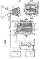
- a molding installation essentially comprises a device for developing a sand structure 1, a device for supplying sand 2, or firing head, a head for refrigeration 3.
- the device for developing a sand structure 1 essentially comprises a chassis-housing 4 formed from side walls 11, a bottom 12 and a wall-cover 13, the assembly being divided in the median plane into two half complementary parts 18 and 19 separated from each other by a model plate 14, essentially consisting of a central support plate 15 and two half-models 16 and 17, the juxtaposition, face against face, in l absence of the support plate 15 represents the shape of the part to be molded.
- These two half-parts 18 and 19 are carried by piston rods 20 and 21.
- the housing is thermally insulated at 22.
- the cover plate 13 is equipped with inlet passages 23 and 24 which are intended to come opposite with clearances 25, 26, respectively formed in a bottom plate 27 of the firing head 2, the seal between the firing head 2 and the device 1 then being provided by seals 28.
- This firing head 2 is adapted to move, with spacing or approximation according to the arrows f 1 , f 2 relative to the device 1 on the one hand and, on the other hand, in translation according to the arrows f 3 and f 4 to come below a hopper sand loading 28.
- the bottom wall 12 is equipped with outlet passages 29, 30, with a sand stop grid.
- the refrigeration head 3 consists of a wall 31 insulated at 32 with a recess 33, the radial extension of which is such that it covers the passages 23 and 24 of the device 1, as shown in the drawings and the seal is also ensured here by a seal 34.
- the recess 33 of this refrigeration head 3 communicates by a conduit 36 and a flexible tube 37 with an outlet 38 d an exchanger 39, an inlet 40 of which is supplied via a pipe 41 with refrigeration gas from a reservoir 42, this refrigeration gas possibly being, for example, compressed air or nitrogen gas.
- the exchanger 39 is cooled by a winding 43 connected by a thermostatic valve 44 to a liquid nitrogen tank 45.
- FIG. 2 it can be seen that the invention is applied to an installation of the same kind as that of FIG. 1, except that it is a question here of forming rigid structures 50 intended to constitute mold cores and no longer mold walls, these cores 50 then being placed in a manner known per se in mold frames which have been produced according to the technique described with reference to FIG. 1, or according to any other previously known technique.
- the invention is also applied to the formation of two half-molds 61 and 62 obtained here again by the presence of a model plate 63, held inside a chassis 64 in which the inlet passages for sand and coolant 65 and 66 can still be recognized here.
- a model plate 63 held inside a chassis 64 in which the inlet passages for sand and coolant 65 and 66 can still be recognized here.
- the main outlet passages for the coolant 67 and 68 which are fitted with filters 69 and 70 adapted to retain the sand, but also, additional inlet passages 71 and 72 have been provided which are connected to the same source of refrigerant gas as the main passages 65 and 66.
- FIG. 3 shows additional outlets at the most inaccessible place of the model in the form of a ring 73 connected: to an inner pipe 75 towards an outlet 76. This ensures local diversion along f 4 , f ′ 4 of the flow of refrigerant gas, precisely in the most inaccessible angle of the model.
- FIG. 5 it can be seen here that, for the formation of two complementary half-molds of the same type as those encountered in the preceding figures, there is here a model plate which is made wholly or partly in porous wall 90, this hollow model being connected at its upper end to an outlet 91, while refrigerant gas inlet passages are formed at different points of the frame at 92, 93, 94, 95, 96, 97, so to create currents which are indicated by the arrows extending all around the model 90.
- the refrigerating fluid thus passes regularly, in a uniform way, through the porous wall of the model and escapes by the exit 91 to the atmosphere.
- FIG. 6 represents the same model structure as that represented in FIG. 5, with the essential difference that the model plate 100 produced in porous wall, is here connected at its upper end to an inlet passage 101 of refrigerated gas, which passes uniformly through the porous wall 102 constituting this model 100 to flow into the mass of sand, before escaping to the lower outlet passages 103, 104 and upper 105 and 106.
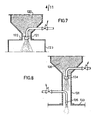
- a firing head 120 contains sand previously moistened and the cooling by the supply of a cooling fluid is ensured by a nozzle 121 formed in a transfer duct 122 and connected to a source of cooling fluid which can be of liquid nitrogen or carbon dioxide under pressure which will be expanded during its distribution in the grains of sand being transferred to the forming walls 123.
- the grains of sand in the firing head 130 are in the insufficiently humidified state and a rehumidification by spraying is carried out in a transfer duct 131 between firing head 130 and forming walls 133. of water by means of a nozzle 134, then cooling by spraying a cooling fluid by means of a nozzle 135.
- FIG. 9 represents a model 140 intended to be inserted into forming walls, as has been represented in FIG. 1.
- the model 140 comprises a metal plate 141 having protrusions such as 142 which are complementary and represent the shape of the object to be manufactured, and protrusions such as 143 forming a source pouring duct.
- the plate 141 is pierced with a plurality of channels 144, leading to clearances 145 closed two by two by studs 146 so as to form a continuous duct 147, for a refrigerant admitted at 148 and withdrawn at 149.
- the plate- support 141 is advantageously trivialized, that is to say that the parts of the model 142 are removable and therefore changed from one manufacture to another without modification of the support plate itself, which forms a heat exchanger for cooling the sand surrounding by simple thermal conduction.
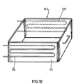
- cooling frames by simple thermal conduction, and in this case, as shown in FIG. 10, it suffices to provide cooling coils 170, 170 ′, in thermal contact externally against certain forming walls. 171 of a chassis 172.
- FIG. 11 shows schematically the adap tion of the invention to a conventional molding line so as to increase its productivity.
- a conventional chain 150 comprises a firing head 151 and forming walls 152, 153, intended to make a structure of molding sand 154, and the various structures 154a, 154b, 154c, 154d, are pushed in a train, so as to form between two structures, for example 154c and 154d, a molding cavity 155.
- a cryogenic chain 160 has been arranged which comprises, as described with reference to FIG.
- the refrigeration device 164 is supplied with refrigerant by a pipe 167 provided with an exchanger 168, in which the coolant is cooled by liquid nitrogen coming from a tank 169.
- the cryogenic sand structures 165 are stored in a waiting tunnel 170 for keeping cold, before t to be transferred by a device 171 to the main chain 150, where they are inserted between the molding structures 154, at the rate of one structure 165 for three structures 154, which makes it possible to improve productivity by 30% .
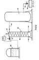
- a cooling head 180 for the sand placed in a molding frame 181 is supplied via the valve 182 with air at -78 ° C at 7 bars withdrawn from a buffer tank 183 charged with air in 184 cooled in an exchanger 185 by heat exchange with carbon dioxide flowing in passages 186, this cold carbon dioxide resulting from the expansion by the valve 187 of a gas stream from a liquid carbon dioxide tank 188 at -20 ° C under a pressure of 20 bars.
- Temperature regulation is ensured by a thermal probe 189 controlling the opening or closing of the valve relaxation 187.
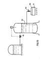
- a gassing head 190 of a molding frame 191 is directly supplied with carbon dioxide at -50 ° C. under a pressure of 7 bars from a storage tank 193, through a valve 192, so that the gas is further cooled, this carbon dioxide at -50 ° C resulting from expansion through a valve 194 of liquid carbon dioxide at -20 ° C at 20 bars.
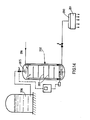
- a gassing head 200 of a molding frame 201 a gaseous mixture at -78 ° C of air and carbon dioxide from a cooling mixer tank 202 with baffles 203, supplied with a portion of air under pressure of 7 bars in 204 and in liquid carbon dioxide sprayed in 205 from a storage tank 206 of liquid carbon dioxide at -20 ° C. under 20 bars.
- a circulation turbine 207 cooperates with the baffles 203 to ensure the homogenization of the refrigerated composite gas thus formed.
- sand molded test pieces were prepared which were cooled to gradually decreasing temperatures from -10 ° C to a value close to -120 ° C to -140 ° C and we noted each time the flexural strength R in kg-cm2.
- Curves A and B were obtained with sand having a water content of 4% and 6% respectively with simple conduction cooling, while curves C and D were also obtained with sand having a water content of 4 % and 6t respectively, but with gas cooling.
Landscapes
- Engineering & Computer Science (AREA)
- Mechanical Engineering (AREA)
- Manufacture Of Alloys Or Alloy Compounds (AREA)
Abstract
Description
La présente invention concerne la fabrication de pièces métalliques par moulage, du genre où l'on élabore, en mettant en oeuvre des parois de formage telles que châssis et modèle, et à partir d'un matériau de moulage constitué de particules humidifiées, une structure rigide destinée à servir, soit de moule recevant le métal en fusion, soit de noyaux destinés à être placés dans un tel moule. Généralement, on utilise comme particules du sable plus ou moins humidifié, auquel on ajoute des produits susceptibles d'assurer, pendant l'opération de moulage, la rigidité de la structure conformée, ces produits étant généralement des produits chimiques, tels que du silicate dessoude ou des résines. La préparation de telles structures composites est relativement complexe, donc coûteuse, et de surcroît présente des inconvénients lors du décochage qui consiste à réduire à nouveau en particules la structure rigide constituée provisoirement pour le moulage et qu'on recycle en vue d'une nouvelle opération de conformation et moulage. Cette opération de décochage est particulièrement difficile pour les noyaux placés dans les moules destinés à former des cavités dans les pièces moulées. De surcroît, le recyclage du matériau en particules nécessite une opération de régénération qui est coûteuse. En outre, l'intervention de produits chimiques de durcissement, tels certaines résines, conduit à une pollution de l'atmosphère ambiante lors de la fabrication des moules, ainsi que pendant la coulée proprement dite, et lors de la régénération du matériau en particules.The present invention relates to the manufacture of metal parts by molding, of the type in which one develops, by using forming walls such as chassis and model, and from a molding material consisting of humidified particles, a structure rigid intended to serve either as a mold receiving the molten metal, or as cores intended to be placed in such a mold. Generally, more or less moistened sand is used as particles, to which are added products capable of ensuring, during the molding operation, the rigidity of the shaped structure, these products generally being chemicals, such as desiccated silicate or resins. The preparation of such composite structures is relatively complex, therefore costly, and moreover has drawbacks during unhooking which consists in reducing again into particles the rigid structure temporarily created for molding and which is recycled for a new operation. of conformation and molding. This release operation is particularly difficult for the cores placed in the molds intended to form cavities in the molded parts. In addition, recycling the particulate material requires an expensive regeneration operation. In addition, the intervention of hardening chemicals, such as certain resins, leads to pollution of the ambient atmosphere during the manufacture of the molds, as well as during the casting proper, and during the regeneration of the particulate material.
La présente invention a pour objet un procédé de fabrication qui est simple et peu coûteux à mettre en oeuvre, qui élimine toute pollution de l'environnement, qui assure une opération de décochage extrêmement simple et qui supprime la régénération du matériau en particules après moulage, tout en assurant une tenue mécanique correcte de la structure en particules. L'invention est partie de cette constatation, qui est connue en soi, que la rigidité d'une structure de particules humidifiées peut être assurée par refroidissement à une température nettement inférieure à la prise en glace à l'aide d'un fluide réfrigérant qui peut être, par exemple, de l'azote liquide en cours de vaporisation ou tout autre fluide approprié. 0n a bien proposé de réaliser de tels moules en aspergeant la surface du moule avec une pulvérisation d'azote liquide ou en faisant transiter les moules conformés dans un châssis à l'intérieur d'un tunnel de réfrigération à basse température. Ces techniques n'ont cependant pas vu le jour au point de vue industriel car, d'une part, elles ne permettaient que la mise en oeuvre de moules d'une certaine forme et notamment des moules dont la face supérieure se présentait librement à l'atmosphère pour recevoir la pulvérisation, d'autre part, elles étaient particulièrement dispendieuses en fluide réfrigérant. Le procédé selon l'invention permet une utilisation économique et efficace de la technique du refroidissement.The subject of the present invention is a manufacturing process which is simple and inexpensive to implement, which eliminates any pollution of the environment, which ensures an extremely simple stripping operation and which suppresses the regeneration of the particulate material after molding, while ensuring correct mechanical strength of the particle structure. The invention is part of this observation, which is known per se, that the rigidity of a structure of humidified particles can be ensured by cooling to a temperature much lower than setting in ice using a refrigerant which can be, for for example, liquid nitrogen during vaporization or any other suitable fluid. It has been proposed to produce such molds by spraying the surface of the mold with a spray of liquid nitrogen or by passing the molds shaped into a frame inside a low temperature refrigeration tunnel. However, these techniques did not emerge from the industrial point of view because, on the one hand, they only allowed the use of molds of a certain shape and in particular molds whose upper face was freely presented to the 'atmosphere to receive the spray, on the other hand, they were particularly expensive in refrigerant. The method according to the invention allows economical and efficient use of the cooling technique.
Selon l'invention, dans un procédé du genre rappelé ci-dessus et qui met en oeuvre un refroidissement accentué, on combine les deux mesures suivantes :
- a) on assure une teneur en eau du matériau de moulage dans une proportion massique eau/ma- tériau comprise entre 3 et 6t et avantageusement entre 4 et 5%.
- b) on assure un refroidissement rapide du matériau de moulage à une température comprise entre -40°C et -110°C et de préférence entre -50°C et -90°C.
- a) a water content of the molding material is ensured in a mass proportion of water / material of between 3 and 6 t and advantageously between 4 and 5%.
- b) rapid cooling of the molding material is ensured at a temperature between -40 ° C and -110 ° C and preferably between -50 ° C and -90 ° C.
Selon une forme de réalisation, l'humidification du matériau de moulage est effectuée avant son introduction entre les parois de formage où est assuré le refroidissement. Selon une variante de mise en oeuvre, le matériau de moulage à l'état insuffisamment humidifié est préalablement refroidi avant son introduction entre les parois de formage et l'on assure l'humidification par une distribution homogène d'eau dans le matériau au cours de son transfert vers lesdites parois de formage. Le refroidissement de la structure intervient d'abord par conduction solide entre les parois de formage à l'état refroidi et les matériaux de la structure, puis, si nécessaire, on atteint la température spécifiée ci-dessus par apport d'un réfrigérant régulièrement réparti dans la masse de ladite structure. Cette dernière opération peut être effectuée par circulation d'un fluide réfrigérant de transit au travers de ladite structure, avantageusement par insufflation d'un fluide réfrigérant mais le réfrigérant régulièrement réparti peut également être constitué de particules réfrigérantes, par exemple de ·l'azote à l'état de brouillard ou pulvérisé, ou de la neige carbonique, intimement mélangées avec le matériau de moulage, juste avant formation de la structure à rigidifier et avantageusement, au cours de l'opération de transfert vers les parois de formage. L'invention concerne également une installation pour mise en oeuvre du procédé ci-dessus.According to one embodiment, the humidification of the molding material is carried out before its introduction between the forming walls where cooling is provided. According to an implementation variant, the molding material in the insufficiently humidified state is previously cooled before its introduction between the forming walls and humidification is ensured by a homogeneous distribution of water in the material during its transfer to said forming walls. The cooling of the structure occurs first by solid conduction between the forming walls in the cooled state and the materials of the structure, then, if necessary, the temperature specified above is reached by adding a regularly distributed coolant. in the mass of said structure. This last operation can be carried out by circulation of a transit coolant through said structure, advantageously by blowing a coolant but the regularly distributed coolant can also be made up of coolant particles, for example nitrogen at the state of mist or spray, or carbon dioxide snow, intimately mixed with the molding material, just before formation of the structure to be stiffened and advantageously, during the transfer operation to the forming walls. The invention also relates to an installation for implementing the above method.
Les caractéristiques et avantages de l'invention ressortiront de la description qui suit à titre d'exemple, en référence aux dessins annexés, dans lesquels :
- - la figure 1 est une vue schématique d'une forme de réalisation de l'invention ;
- - la figure 2 est une vue partielle d'une variante de réalisation selon l'invention ;
- - les figures 3 à 10 sont huit autres variantes de la mise en oeuvre de l'invention.
- - la figure 11 est une vue en perspective cavalière, avec arrachement partiel d'une autre variante de l'invention ;
- - les figures 12, 13 et 14 sont des vues schématiques de quatre mises en oeuvre particulières de l'invention.
- -La figure 15 rèprésente des diagrammes montrant la résistance mécanique d'une éprouvette de sable (ordonnée)en fonction de la température (abscisse).
- - Figure 1 is a schematic view of an embodiment of the invention;
- - Figure 2 is a partial view of an alternative embodiment according to the invention;
- - Figures 3 to 10 are eight other variants of the implementation of the invention.
- - Figure 11 is a perspective view, partially broken away of another variant of the invention;
- - Figures 12, 13 and 14 are schematic views of four particular implementations of the invention.
- -Figure 15 shows diagrams showing the mechanical resistance of a sand specimen (ordered) as a function of temperature (abscissa).
En-se référant à la figure 1, on voit qu'une installation de moulage comporte essentiellement un dispositif d'élaboration d'une structure en sable 1, un dispositif d'alimentation en sable'2, ou tête de tir, une tête de réfrigération 3.Referring to FIG. 1, it can be seen that a molding installation essentially comprises a device for developing a sand structure 1, a device for supplying sand 2, or firing head, a head for refrigeration 3.
Le dispositif d'élaboration de structure en sable 1 comporte essentiellement un boîtier-châssis 4 formé de parois latérales 11, d'un fond 12 et d'une paroi-couvercle 13, l'ensemble étant divisé dans le plan médian en deux demi-parties complémentaires 18 et 19 séparées l'une de l'autre par une plaque-modèle 14, constituée essentiellement d'une plaque-support centrale 15 et de deux demi-modèles 16 et 17, dont la juxtaposition, face contre face, en l'absence de la plaque-support 15, représente la forme de la pièce à mouler. Ces deux demi-parties 18 et 19 sont portées par des tiges de piston 20 et 21. Le boîtier est thermiquement isolé en 22. La plaque-couvercle 13 est équipée de passages d'entrée 23 et 24 qui sont destinés à venir en regard avec des dégagements 25, 26, respectivement ménagés dans une plaque de fond 27 de la tête de tir 2, l'étanchéité entre la tête de tir 2 et le dispositif 1 étant alors assurée par des joints 28. Cette tête de tir 2 est adaptée à se déplacer, à écartement ou rapprochement selon les flèches f1, f2 par rapport au dispositif 1 d'une part et, d'autre part, à translation selon les flèches f3 et f4 pour venir en-dessous d'une trémie de chargement de sable 28. La paroi de fond 12 est équipée de passages de sortie 29, 30, à grille d'arrêt du sable.The device for developing a sand structure 1 essentially comprises a chassis-
La tête de réfrigération 3 est constituée d'une paroi 31 isolée en 32 avec un évidement 33, dont l'exten- tion radiale est telle qu'elle permet de recouvrir les passages 23 et 24 du dispositif 1, comme représenté aux dessins et l'étanchéité étant également assurée ici par un joint 34. L'évidement 33 de cette tête de réfrigération 3 communique par un conduit 36 et un tube flexible 37 avec une sortie 38 d'un échangeur 39, dont une entrée 40 est alimentée via une canalisation 41 en gaz de réfrigération à partir d'un réservoir 42, ce gaz de réfrigération pouvant être par exemple de l'air comprimé ou de l'azote gazeux. L'échangeur 39 est refroidi par un enroulement 43 raccordé par une vanne thermostatique 44 à un réservoir d'azote liquide 45.The refrigeration head 3 consists of a
L'installation, telle qu'elle vient d'être décrite, fonctionne de la façon suivante :
- Dans une première phase, la tête de tir 2 ayant reçu de la*
trémie 28 une charge de sable humide est amenée, selon les deux mouvements de translation f4 et f2, contre laparoi 13 du dispositif 1, lespassages 25 et 26 de la tête de tir 2 étant en regard desentrées 23 et 24 de la plaque-couvercle 13. La charge de sable est, de façon connue en soi, maintenue dans la tête de tir 2 par des membranes appropriées permettant la retenue du sable en l'absence de toute pression et, au contraire, laissant échapper le sable lors de la mise sous pression de la tête de tir 2. Dans la position décrite, la tête de tir 2 est alors mise sous pression par une canalisation 46 raccordée auréservoir 42 et le sable peut s'écouler ainsi de la tête de tir 2 vers la cavité ménagée entre le modèle intérieur 15 et les parois de châssis, l'ensemble constituant des parois de formage d'une structure en sable. Le sable ainsi transféré occupe tout l'espace ainsi dégagé, tandis que le gaz sous pression ayant assuré le transfert du sable peut s'échapper librement au travers des passages desortie 29 et 30. Une fois cette opération terminée, la tête de tir 2 est dégagée de l'ensemble 1, selon les mouvement f1 et f3 de façon à venir en-dessous de la trémie dechargement 28 pour recevoir une nouvelle charge, tandis que la tête de réfrigération 3 vient s'appliquer sur la paroi supérieure 13 de l'ensemble 1 avec une étanchéité due aujoint 34, après quoi un gaz réfrigéré dans l'échangeur 39, provenant duréservoir 42, est transféré par la tête de réfrigération au travers des passages d'entrée 23 et 24 et de là, s'écouler selon les flèches f et f' au travers de la masse de sable pour s'échapper à l'air libre par lessorties 29 et 30. Ce gaz réfrigéré qui est à une température régulée comprise entre - 40°C et - 110°C, si l'azote liquide est utilisé, assure ainsi une réfrigération dans la masse du sable destinée à rigidifier la structure préalablement conformée et lorsque la température de la masse du sable a atteint la température appropriée, la tête de réfrigération 3 est dégagée, et les deux parties duchâssis 16 et 17 peuvent être séparées par retrait des tiges depiston 20 et 21 et lemodèle 14 peut être alors dégagé permettant ainsi la réunion, en tout endroit approprié, des deux demi-moules en sable ainsi formés, le passage d'admission du produit liquide à mouler étant formé par certaines surépaisseurs de laplaque modèle 14. L'opération de moulage du métal doit être effectuée, bien entendu, dans un délai relativement court de façon à éviter tout réchauffement intempestif de la structure de moulage qui a été rigidifiée par effet cryogénique.
- In a first phase, the head of shot 2 having received * hopper 28 a wet sand load is brought, according to the two translational movements f 4 and f 2, against the
wall 13 of the device 1, thepassages inlets cover plate 13. The charge of sand is, in a manner known per se, maintained in the firing head 2 by suitable membranes allowing the retention of the sand in the absence of any pressure and, on the contrary, letting the sand escape when the firing head 2 is pressurized. In the position described, the firing head 2 is then pressurized by a pipe 46 connected to thereservoir 42 and the sand can thus flow from the firing head 2 towards the cavity formed between theinterior model 15 and the chassis walls, the assembly constituting walls for forming a sand structure. The sand thus transferred occupies all the space thus released, while the pressurized gas having ensured the transfer of the sand can escape freely through theoutlet passages tré loading crumb 28 to receive a new load, while the refrigeration head 3 is applied to theupper wall 13 of the assembly 1 with a seal due to theseal 34, after which a refrigerated gas in theexchanger 39, coming from thereservoir 42, is transferred by the refrigeration head through theinlet passages outlets chassis piston rods model 14 can then be released thus allowing the meeting, in any appropriate place, of the two sand half-molds thus formed, the inlet passage for the liquid product to be molded being formed by certain extra thicknesses of themodel 14 plate. The metal molding operation must be carried out, of course, within a relatively short time so as to avoid any untimely heating of the molding structure which has been stiffened by the cryogenic effect.
En se référant à la figure 2, on voit que l'invention est appliquée à une installation du même genre que celle de la figure 1, à cette différence près qu'il s'agit ici de former des structures rigides 50 destinées à constituer des noyaux de moule et non plus des parois de moule, ces noyaux 50 étant alors placés de façon connue en soi dans des châssis de moule qui ont été réalisés selon la technique décrite en référence à la figure 1, ou selon toute autre technique antérieurement connue. En effet, il peut y avoir intérêt à fabriquer spécialement des noyaux de sable rigidifiés par voie cryogénique alors que le reste du moule est lui-même formé de sable rigidifié par des produits chimiques, car il est bien clair que les noyaux; cryogéniques peuvent être très aisément dégagés de la pièce moulée, puisque l'opération de moulage a détruit, par réchauffement, la rigidité de la structure cryogénique.Referring to FIG. 2, it can be seen that the invention is applied to an installation of the same kind as that of FIG. 1, except that it is a question here of forming
Selon la variante de réalisation décrite à la figure 3, l'invention est encore appliquée à la formation de deux demi-moules 61 et 62 obtenus ici toujours par la présence d'une plaque-modèle 63, maintenue à l'intérieur d'un châssis 64 où l'on reconnaît encore ici les passages d'entrée de sable et de fluide réfrigérant 65 et 66. Ici, on dispose, non seulement de passages de sortie principaux pour le fluide réfrigérant 67 et 68, qui sont équipés de filtres 69 et 70 adaptés à retenir le sable, mais également, on a prévu des passages d'entrée additionnels 71 et 72 qui sont raccordés à la même source de gaz réfrigérant que les passages principaux 65 et 66. On assure ainsi, non seulement la formation d'un courant principal selon les flèches f3 et f'3, mais également la superposition d'un courant complémentaire selon les flèches f"3 et f"'3 au travers des passages 71 et 73, ce courant complémentaire ayant pour but d'assurer une réfrigération complémentaire autour de zones à large extension radiale du modèle intérieur, qui, sinon, seraient imparfaitement refroidies par le flux principal.According to the variant embodiment described in FIG. 3, the invention is also applied to the formation of two half-
Egalement, on peut prévoir, dans certains cas, des sorties supplémentaires et l'on a représenté à cette figure 3 des sorties supplémentaires à l'endroit le plus inaccessible du modèle sous forme d'une couronne 73 raccordée: à une conduite intérieure 75 vers une sortie 76. On assure ainsi une dérivation locale selon f4, f'4 du flux de gaz réfrigérant, précisément dans l'angle le plus inaccessible du modèle.Also, provision can be made, in certain cases, for additional outlets and FIG. 3 shows additional outlets at the most inaccessible place of the model in the form of a ring 73 connected: to an
En se référant à la figure 4, on retrouve ici la même structure que celle qui a été indiquée à la figure 3 et les mêmes chiffres de références désignent les mêmes éléments, à cette différence près que les passages pour l'entrée du gaz réfrigérant pour cette variante sont ici représentés par des bouchons poreux 80 pour l'entrée et 81 et 82 pour les sorties principales, et 83, 84 pour des admissions complémentaires de gaz de réfrigération.Referring to Figure 4, we find here the same structure as that which was indicated in Figure 3 and the same reference numbers designate the same elements, except that the passages for the inlet of the refrigerant gas for this variant is here represented by
En se référant à la figure 5, on voit ici que, pour la formation des deux demi-moules complémentaires du même type que ceux rencontrés aux figures précédentes, on dispose ici d'une plaque-modèle qui est réalisée en tout ou en partie en paroi poreuse 90, ce modèle creux étant raccordé à son extrémité supérieure à une sortie 91, tandis que des passages d'entrées de gaz réfrigérant sont ménagés en différents points du châssis en 92, 93, 94, 95, 96, 97, de façon à créer des courants qui sont indiqués par les flèches s'étageant tout autour du modèle 90. Le fluide de réfrigération passe ainsi régulièrement, d'une façon uniforme, au travers de la paroi poreuse du modèle et s'échappe par la sortie 91 à l'atmosphère.Referring to FIG. 5, it can be seen here that, for the formation of two complementary half-molds of the same type as those encountered in the preceding figures, there is here a model plate which is made wholly or partly in porous wall 90, this hollow model being connected at its upper end to an
La disposition selon la figure 6. représente la même structure de modèle que celle représentée à la figure 5, à cette différence essentielle que la plaque-modèle 100 réalisée en paroi poreuse, est ici raccordée à son extrémité supérieure à un passage d'entrée 101 de gaz réfrigéré, qui traverse de façon uniforme la paroi poreuse 102 constituant ce modèle 100 pour s'écouler dans la masse de sable, avant de s'échapper vers les passages de sorties inférieurs 103, 104 et supérieurs 105 et 106.The arrangement according to FIG. 6 represents the same model structure as that represented in FIG. 5, with the essential difference that the
Selon la figure 7 une tête de tir 120 contient du sable préalablement humidifié et le refroidissement par apport d'un fluide réfrigérant est assuré par un gicleur 121 ménagé dans un conduit de transfert 122 et raccordé à une source de fluide réfrigérant qui peut être de l'azote liquide ou du gaz carbonique sous pression qui sera détendu lors de sa distribution dans les grains de sable en cours de transfert vers les parois de formage 123.According to FIG. 7, a firing
Selon la figure 8, les grains de sable dans la tête de tir 130 sont à l'état insuffisamment humidifié et l'on procède dans un conduit de transfert 131 entre tête de tir 130 et parois de formage 133 à une réhumidifi- cation par pulvérisation d'eau au moyen d'un gicleur 134, puis refroidissement par pulvérisation d'un fluide réfrigérant au moyen d'un gicleur 135.According to FIG. 8, the grains of sand in the
La figure 9 représente un modèle 140 destiné à être inserré dans des parois de formage, comme cela a été représenté à la figure 1. Le modèle 140 comporte une plaque métallique 141 ayant des protubérances telles que 142 qui sont complémentaires et représentent la forme de l'objet à fabriquer, et des protubérances telles 143 formant un conduit de coulée en source. La plaque 141 est percée d'une pluralité de canaux 144, aboutissant à des dégagements 145 obturés deux à deux par des plots 146 de façon à former un conduit continu 147, pour un fluide réfrigérant admis en 148 et soutiré en 149. La plaque-support 141 est avantageusement banalisée, c'est-à-dire que les parties du modèle 142 sont amovibles et donc changées d'une fabrication à une autre sans modification de la plaque support elle-même, qui forme échangeur de chaleur pour refroidissement du sable environnant par simple conduction thermique.FIG. 9 represents a
Bien entendu, on peut également prévoir des châssis de refroidissement par simple conduction thermique, et dans ce cas, comme représenté à la figure 10, il suffit de prévoir des serpentins de refroidissement 170, 170', en contact thermique extérieurement contre certaines parois de formage 171 d'un châssis 172.Of course, it is also possible to provide cooling frames by simple thermal conduction, and in this case, as shown in FIG. 10, it suffices to provide
La figure 11 représente schématiquement l'adaptation de l'invention à une chaîne de moulage classique de façon à accroître sa productivité. Ici, une chaîne classique 150 comporte une tête de tir 151 et des parois de formage 152, 153, destinées à confectionner une structure en sable de moulage 154, et les différentes structures 154a, 154b, 154c, 154d, sont poussées en un train, de façon à former entre deux structures, par exemple 154c et 154d, une cavité de moulage 155. A côté de cette chaîne 150, on a agencé une chaîne cryogénique 160 qui comporte de la façon décrite en référence à la figure 1, une tête de tir 161 alimentée en sable par une dérivation 162 d'une boucle de recyclage 163, et un dispositif de réfrigération 164 adapté à réfrigérer une structure 165 réalisée entre les parois de formage 166. Le dispositif de réfrigération 164 est alimenté en fluide réfrigérant par une conduite 167 munie d'un échangeur 168, dans lequel le fluide réfrigérant est refroidi par de l'azote liquide provenant d'un réservoir 169. Les structures cryogéniques en sable 165 sont stockées dans un tunnel d'attente 170 de maintien en froid, avant d'être transférées par un dispositif 171 vers la chaîne principale 150, où elles s'intercalent entre les structures de moulage 154, à raison d'une structure 165 pour trois structures 154, ce qui permet d'améliorer la productivité de 30%.Figure 11 shows schematically the adap tion of the invention to a conventional molding line so as to increase its productivity. Here, a
Selon la figure 12, une tête de refroidissement 180 pour le sable placé dans un chassis de moulage 181 est alimentée via la vanne 182 en air à -78°C sous 7 bars soutiré d'un réservoir tampon 183 chargé en air en 184 refroidi dans un échangeur 185 par échange thermique avec du gaz carbonique circulant dans des passages 186, ce gaz carbonique froid résultant de la détente par la vanne 187 d'un courant gazeux issu d'un réservoir de gaz carbonique liquide 188 à -20°C sous une pression de 20 bars. Une régulation de température est assurée par une sonde thermique 189 commandant l'ouverture ou la fermeture de la vanne de détente 187.According to FIG. 12, a cooling
Selon la figure 13, une tête de gazage 190 d'un châssis de moulage 191 est directement alimenté en gaz carbonique à -50°C sous une pression de 7 bars d'un réservoir de stockage 193, au travers d'une vanne 192, de sorte que le gaz subit encore un refroidissement, ce gaz carbonique à -50°C résultant de la détente au travers d'une vanne 194 de gaz carbonique liquide à -20°C sous 20 bars.According to FIG. 13, a gassing
Selon la figure 14, on injecte dans une tête de gazage 200 d'un châssis de moulage 201 un mélange gazeux à -78°C d'air et de gaz carbonique issu d'un réservoir mélangeur refroidisseur 202 à chicanes 203, alimenté d'une part en air sous pression de 7 bars en 204 et en gaz carbonique liquide pulvérisé en 205 en provenance d'un réservoir de stockage 206 de gaz carbonique liquide à -20°C sous 20 bars. Une turbine de circulation 207 coopère avec les chicanes 203 pour assurer l'homogénéisation du gaz composite réfrigéré ainsi formé.According to Figure 14, is injected into a gassing
Selon la figure 15, on a préparé des éprouvettes moulées en sable que l'on a refroidi à des températures progressivement décroissantes depuis -10°C jusqu'à une valeur voisine de -120°C à -140°C et l'on a noté chaque fois la résistance à la flexion R en kg-cm2. Les courbes A et B ont été obtenues avec du sable ayant une teneur en eau de 4% et 6% respectivement avec refroidissement par simple conduction, tandis que les courbes C et D ont été obtenues également avec du sable ayant une teneur en eau de 4% et 6t respectivement, mais avec refroidissement par gazage.According to FIG. 15, sand molded test pieces were prepared which were cooled to gradually decreasing temperatures from -10 ° C to a value close to -120 ° C to -140 ° C and we noted each time the flexural strength R in kg-cm2. Curves A and B were obtained with sand having a water content of 4% and 6% respectively with simple conduction cooling, while curves C and D were also obtained with sand having a water content of 4 % and 6t respectively, but with gas cooling.
On constate d'abord que la résistance mécanique est d'autant plus élevée que la teneur en eau est plus forte. On constate également que la résistance mécanique croît rapidement de -10°C jusqu'à -110°C environ pour les courbes B et D (teneur en eau de 6 %) et jusqu'à -95°C environ pour les courbes A et C (teneur en eau de 4%) puis décroît ensuite très brusquement. De ces courbes, il ressort que la température de réfrigération ne doit en tous cas pas descendre en-dessous de -110°C et de préférence ne doit pas descendre en-dessous de -90°C, sinon des risques de chute brutale de la résistance mécanique risqueraient de se produire. De même, il est exclu de pouvoir opérer à une température supérieure à -40°C, car la résistance mécanique, surtout avec une teneur en eau de 4%, deviendrait alors insuffisante. Avantageusement, on ne doit pas opérer à une température supérieure à -50°C, assurant une résistance mécanique au moins égale à 25 kg-cm2.First of all, it is found that the mechanical strength is higher the higher the water content. We also note that the mechanical resistance increases rapidly from -10 ° C to approximately -110 ° C for curves B and D (water content of 6%) and up to approximately -95 ° C for curves A and C (4% water content) then decreases very suddenly. From these curves, it emerges that the refrigeration temperature must in any case not drop below -110 ° C and preferably must not drop below -90 ° C, otherwise the risk of a sudden drop in the mechanical resistance may occur. Similarly, it is excluded to be able to operate at a temperature above -40 ° C, because the mechanical strength, especially with a water content of 4%, would then become insufficient. Advantageously, one should not operate at a temperature above -50 ° C, ensuring a mechanical strength at least equal to 25 kg-cm2.
Il faut noter que le relevé de ces courbes A, B, C, D, a été fait dans des conditions dites de refroidissement "rapide" de l'ordre d'une ou quelques minutes (vitesse de propagation de l'ordre du centimètre/minute -0,5 à 1,5 cm/mn), et qu'on obtient des résultats très différents en cas de refroidissement lent, de l'ordre de 30 minutes. Ainsi la température "critique" relevée sur les courbes de l'ordre de -110°C (teneur en eau de 6%) ou de -95°C (teneur en eau de 4%) est une caractéristique spécifique au refroidissement "rapide" et ne se retrouve nullement au refroidissement lent, où les maxima de*résistance mécanique sont extrêmement applatis, en sorte que la mise en oeuvre d'un refroidissement lent conduirait à une gamme de températures utilisables considérablement plus large que celle susceptible en refroidissement "rapide". Or une propagation "rapide",par conduction et/ou gazage, du front froid est indispensable industriellement.It should be noted that the reading of these curves A, B, C, D, was made under conditions known as "rapid" cooling of the order of one or a few minutes (propagation speed of the order of a centimeter / minute -0.5 to 1.5 cm / min), and that very different results are obtained in the event of slow cooling, of the order of 30 minutes. Thus the "critical" temperature noted on the curves of the order of -110 ° C (water content of 6%) or -95 ° C (water content of 4%) is a specific characteristic of "rapid" cooling. and is found not to slow cooling, where maxima * mechanical strength are extremely flattened, so that the implementation of a slow cooling would lead to a usable temperature range considerably broader than likely cooling "fast" . However, a "rapid" propagation, by conduction and / or gassing, of the cold front is essential industrially.
Claims (28)
Applications Claiming Priority (2)
| Application Number | Priority Date | Filing Date | Title |
|---|---|---|---|
| FR8119038 | 1981-10-09 | ||
| FR8119038A FR2514274A1 (en) | 1981-10-09 | 1981-10-09 | PROCESS AND INSTALLATION FOR MANUFACTURING METALLIC PARTS BY SAND MOLDING OR THE LIKE |
Publications (1)
| Publication Number | Publication Date |
|---|---|
| EP0077247A1 true EP0077247A1 (en) | 1983-04-20 |
Family
ID=9262892
Family Applications (1)
| Application Number | Title | Priority Date | Filing Date |
|---|---|---|---|
| EP82401791A Withdrawn EP0077247A1 (en) | 1981-10-09 | 1982-10-01 | Method and apparatus for the production of metal articles by casting in sand or the like |
Country Status (4)
| Country | Link |
|---|---|
| EP (1) | EP0077247A1 (en) |
| JP (1) | JPS5874243A (en) |
| CA (1) | CA1209780A (en) |
| FR (1) | FR2514274A1 (en) |
Cited By (3)
| Publication number | Priority date | Publication date | Assignee | Title |
|---|---|---|---|---|
| FR2566687A1 (en) * | 1984-06-27 | 1986-01-03 | Air Liquide | DEVICE FOR MANUFACTURING FROZEN MOLDS OR MOLDING CORES |
| WO1997001407A1 (en) * | 1995-06-24 | 1997-01-16 | Air Products And Chemicals, Inc. | Method for forming a mould for use in casting and mould formed by said method |
| KR20240068656A (en) * | 2022-11-04 | 2024-05-17 | 난징 유니버시티 오브 에어로노틱스 앤드 애스트로노틱스 | High-efficiency freezing method and device through various paths of frozen sand mold using internal micropores |
Families Citing this family (2)
| Publication number | Priority date | Publication date | Assignee | Title |
|---|---|---|---|---|
| JP5958892B2 (en) * | 2012-01-23 | 2016-08-02 | 国立研究開発法人産業技術総合研究所 | Frozen core manufacturing method and core molding mold used therefor |
| CN112077262A (en) * | 2020-09-03 | 2020-12-15 | 北京机科国创轻量化科学研究院有限公司 | 3D printing forming method and device for freezing composite casting mold |
Citations (4)
| Publication number | Priority date | Publication date | Assignee | Title |
|---|---|---|---|---|
| CA447141A (en) * | 1948-03-09 | Forbes Blackwood Peter | Casting apparatus | |
| GB1537471A (en) * | 1975-08-14 | 1978-12-29 | Booth & Co Ltd W H | Foundry mould production |
| DE2909839A1 (en) * | 1979-03-13 | 1980-09-25 | Linde Ag | Foundry moulds made by freezing moist sand - where sand cooled by liq. nitrogen is mixed with damp sand and driven into moulding box (OE 15.3.80) |
| FR2454859A1 (en) * | 1979-04-28 | 1980-11-21 | Inst Odlewnictwa | PROCESS FOR CURING MOLDS AND FOUNDRY CORES BY FREEZING LIQUID SAND COMPONENTS |
Family Cites Families (3)
| Publication number | Priority date | Publication date | Assignee | Title |
|---|---|---|---|---|
| JPS5584249A (en) * | 1978-12-16 | 1980-06-25 | Nippon Sanso Kk | Production of mold |
| JPS566754A (en) * | 1979-06-27 | 1981-01-23 | Kubota Ltd | Freezing method of refrigerating mold |
| JPS56128640A (en) * | 1980-03-13 | 1981-10-08 | Sintokogio Ltd | Molding method of green sand mold |
-
1981
- 1981-10-09 FR FR8119038A patent/FR2514274A1/en active Granted
-
1982
- 1982-09-30 CA CA000412620A patent/CA1209780A/en not_active Expired
- 1982-10-01 EP EP82401791A patent/EP0077247A1/en not_active Withdrawn
- 1982-10-09 JP JP17701182A patent/JPS5874243A/en active Pending
Patent Citations (4)
| Publication number | Priority date | Publication date | Assignee | Title |
|---|---|---|---|---|
| CA447141A (en) * | 1948-03-09 | Forbes Blackwood Peter | Casting apparatus | |
| GB1537471A (en) * | 1975-08-14 | 1978-12-29 | Booth & Co Ltd W H | Foundry mould production |
| DE2909839A1 (en) * | 1979-03-13 | 1980-09-25 | Linde Ag | Foundry moulds made by freezing moist sand - where sand cooled by liq. nitrogen is mixed with damp sand and driven into moulding box (OE 15.3.80) |
| FR2454859A1 (en) * | 1979-04-28 | 1980-11-21 | Inst Odlewnictwa | PROCESS FOR CURING MOLDS AND FOUNDRY CORES BY FREEZING LIQUID SAND COMPONENTS |
Cited By (7)
| Publication number | Priority date | Publication date | Assignee | Title |
|---|---|---|---|---|
| FR2566687A1 (en) * | 1984-06-27 | 1986-01-03 | Air Liquide | DEVICE FOR MANUFACTURING FROZEN MOLDS OR MOLDING CORES |
| EP0171304A1 (en) * | 1984-06-27 | 1986-02-12 | L'air Liquide, Societe Anonyme Pour L'etude Et L'exploitation Des Procedes Georges Claude | Apparatus for making frozen moulds or mould cores |
| US4644995A (en) * | 1984-06-27 | 1987-02-24 | L'air Liquide, Societe Anonyme Pour L'etude Et L'exploitation Des Procedes Georges Claude | Device for fabricating frozen moulding moulds or cores |
| WO1997001407A1 (en) * | 1995-06-24 | 1997-01-16 | Air Products And Chemicals, Inc. | Method for forming a mould for use in casting and mould formed by said method |
| KR20240068656A (en) * | 2022-11-04 | 2024-05-17 | 난징 유니버시티 오브 에어로노틱스 앤드 애스트로노틱스 | High-efficiency freezing method and device through various paths of frozen sand mold using internal micropores |
| EP4393618A4 (en) * | 2022-11-04 | 2025-03-05 | Nanjing University of Aeronautics and Astronautics | Multi-path internally-microporous efficient refrigeration method and device for frozen sand mold |
| AU2023370591B2 (en) * | 2022-11-04 | 2025-10-23 | Nanjing University Of Aeronautics And Astronautics | Multi-path internally-microporous efficient refrigeration method and device for frozen sand mold |
Also Published As
| Publication number | Publication date |
|---|---|
| CA1209780A (en) | 1986-08-19 |
| FR2514274B1 (en) | 1984-05-25 |
| JPS5874243A (en) | 1983-05-04 |
| FR2514274A1 (en) | 1983-04-15 |
Similar Documents
| Publication | Publication Date | Title |
|---|---|---|
| JP3819849B2 (en) | Annular mold | |
| CN106715003B (en) | Manufacturing method of iron metal casting | |
| EP0255526B1 (en) | Method for accumulating and restoring cold and device for implementing such method | |
| FR2479717A1 (en) | PROCESS FOR THE PRODUCTION BY LOST WAX MOLDING OF A CERAMIC MOLD CONTAINING A BREAKING CORE | |
| US5033532A (en) | Die casting method | |
| EP0412111A1 (en) | Device for producing ice balls and application to the projection of such ice balls for surface treatments. | |
| CA1209780A (en) | Method and installation for the manufacture of metal parts cast in sand molds and the like | |
| FR2845028A1 (en) | METHOD FOR ROTOMULATING A WORKPIECE COMPRISING A THERMOPLASTIC FOAM LAYER | |
| EP0225203B1 (en) | Process and tunnel for the superficial cooling of foodstuffs | |
| EP2357049B1 (en) | Lost pattern casting process and apparatus for the execution of this process | |
| EP0854334A1 (en) | Container for receiving carbon dioxide snow | |
| FR2534832A1 (en) | APPARATUS AND TECHNIQUE FOR DIRECT CASTING OF METAL SHELLS | |
| CA1246830A (en) | A device used for manufacture of frozen molds or molding cores | |
| FR2764779A1 (en) | PROCESS AND INSTALLATION FOR DIP MOLDING OF VARIOUS PARTS | |
| EP2244872B1 (en) | Mould device for rotational moulding machine and rotational moulding machine including same | |
| CH682390A5 (en) | Container for transporting e.g. bitumen, in solid state | |
| FR2608560A1 (en) | Automatic packing of sprayed bitument in polyolefin film | |
| EP0379410B1 (en) | Device for attaching and cooling a graphite block of a graphite mould wall | |
| CH466552A (en) | Manufacturing process of a hollow body | |
| US3429361A (en) | Method and apparatus for producing metal castings using molten metal cooled before teeming | |
| US20070277952A1 (en) | Rapid localized directional solidification of liquid or semi-solid material contained by media mold | |
| FR2459212A1 (en) | METHOD AND DEVICE FOR MOLDING MOLTEN CERAMIC MATERIALS | |
| KR20090020080A (en) | Die casting method | |
| FR3075684A1 (en) | MONOBLOC MOLD FOUNDATION WITH OPTIMIZED FLUIDIC CIRCULATION | |
| BE1018999A5 (en) | METHOD AND DEVICE FOR MANUFACTURING MAGNETRON CATHODIC SPUTTER TARGET. |
Legal Events
| Date | Code | Title | Description |
|---|---|---|---|
| PUAI | Public reference made under article 153(3) epc to a published international application that has entered the european phase |
Free format text: ORIGINAL CODE: 0009012 |
|
| 17P | Request for examination filed |
Effective date: 19821006 |
|
| AK | Designated contracting states |
Designated state(s): AT BE CH DE FR GB IT LI LU NL SE |
|
| STAA | Information on the status of an ep patent application or granted ep patent |
Free format text: STATUS: THE APPLICATION HAS BEEN WITHDRAWN |
|
| 18W | Application withdrawn |
Withdrawal date: 19860416 |
|
| RIN1 | Information on inventor provided before grant (corrected) |
Inventor name: GOUMY, DANIEL Inventor name: DEFRANCQ, CHARLES Inventor name: GODINO, CLAUDE |