EP0077250A1 - Mount for an antenna for satellite television reception and unit formed by such a support with its antenna - Google Patents
Mount for an antenna for satellite television reception and unit formed by such a support with its antenna Download PDFInfo
- Publication number
- EP0077250A1 EP0077250A1 EP82401799A EP82401799A EP0077250A1 EP 0077250 A1 EP0077250 A1 EP 0077250A1 EP 82401799 A EP82401799 A EP 82401799A EP 82401799 A EP82401799 A EP 82401799A EP 0077250 A1 EP0077250 A1 EP 0077250A1
- Authority
- EP
- European Patent Office
- Prior art keywords
- mast
- antenna
- collar
- support according
- support
- Prior art date
- Legal status (The legal status is an assumption and is not a legal conclusion. Google has not performed a legal analysis and makes no representation as to the accuracy of the status listed.)
- Withdrawn
Links
- 239000002184 metal Substances 0.000 claims description 6
- 230000000903 blocking effect Effects 0.000 claims description 3
- 230000000694 effects Effects 0.000 claims 1
- 239000003351 stiffener Substances 0.000 description 4
- 238000009434 installation Methods 0.000 description 3
- 230000005540 biological transmission Effects 0.000 description 1
- 238000004519 manufacturing process Methods 0.000 description 1
Images

Classifications
-
- H—ELECTRICITY
- H01—ELECTRIC ELEMENTS
- H01Q—ANTENNAS, i.e. RADIO AERIALS
- H01Q1/00—Details of, or arrangements associated with, antennas
- H01Q1/12—Supports; Mounting means
- H01Q1/125—Means for positioning
Definitions
- the invention relates to an antenna support intended to receive emissions, in particular from television, coming from a geostationary satellite as well as to the assembly formed by such a support and its antenna.
- the satellite being geostationary the parabolic reflector must have a well-determined position, adjusted once and for all.
- the adjustment which must be carried out during the installation of such an antenna must be simple so that it can be implemented by persons not having particular knowledge of mechanics.
- This support comprises a steering post fixed relative to the ground, in particular the vertical direction, which can rotate around its longitudinal axis to adjust the azimuth of the antenna and an articulated quadrilateral of which one side constitutes a part of the antenna and another side is a part of the pole, the length of this part of the pole being adjustable and determining the site of the antenna.
- Such a support is easily adjustable and can be manufactured inexpensively.
- the invention aims to improve the support described in this patent application so that its installation is even easier without complicating its manufacture.
- the support according to the invention is therefore of the type of that of patent application 35930, that is to say comprising a quadrilateral or other articulated polygon of which one side constitutes a part of the antenna and another side, of length adjustable, is part of the. pole, and it is characterized in that one of the other sides, lying between the pole and the antenna, also has an adjustable length so as to allow additional adjustment of the antenna site.
- the adjustment of the length of the side forming part of the post can constitute an approximate adjustment of the antenna site while the fine adjustment is obtained by adjusting the length of the other side.
- the side of adjustable length between the antenna and the post comprises an arm articulated by one of its ends to the antenna and, to allow the length adjustment, the other end of this arm is curved and sliding in a ring or necklace secured to the post.
- the fine adjustment is obtained by a simple sliding movement.
- said ring in which slides the curved end on the side of adjustable length, is also sliding on the post.
- the same control means can be provided to block the ring, thus in two parts, respectively on the post and on the arm with curved end; so that the approximate adjustment precedes the fine adjustment it is then preferable for the double ring to be such that the blocking on the post is obtained before the blocking on the curved end.
- the clearance between the ring and the post is less than the clearance between this ring and the curved end.
- the invention also relates to the case where only the side between the post and the reflector is of variable length, the adjustment of the site being thus obtained only by adjusting the length of this side.
- the invention relates to an antenna support comprising a fixed, especially vertical, steering mast relative to the ground, and which can rotate about its axis. longitudinal to adjust the azimuth of the antenna and a polygon, such as a quadrilateral, articulated of which one side constitutes a part of the antenna and another side is a part of the pole, this support being characterized in that a side of this polygon between the mast and the antenna has an adjustable length to allow adjustment of the antenna site thanks to a curved end sliding in a collar secured to the mast.
- the antenna 1 ( Figure 1) is intended to receive television broadcasts from a geostationary satellite. It includes a reflector in the shape of an axis 2 axis directed towards the satellite. This reflector reflects the waves on a sensor (not shown) connected by cable to one or more television receivers.
- the orientation of axis 2 is therefore carried out once and for all during the installation of the antenna. This setting of the direction of the axis 2 must however be able to be modified to take account of a possible change of position of the satellite or of the replacement of this satellite by another.
- the support comprises a vertical mast or post 3 constituted by a metal tube of circular section fixed by two flanges respectively lower 4 and upper 5 to a wall 6 or another fixed element.
- the upper end 7 of the mast 3 protrudes above the flange 5.
- the flanges 4 and 5 are provided with bolts and clamping nuts 8 to hold the mast 3 in these flanges. Thus, before tightening, the mast can rotate around its vertical axis 3a to adjust the azimuth of the reflector 1.
- the mast 3 is connected to a stiffener 9 secured to the rear face of the reflector 1 by means of an arm 10 inclined at approximately 45 ° relative to the horizontal and in the shape of a stirrup and of a tubular arm 11 These two arms are articulated to the stiffener 9.
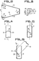
- the arm 10 has the general shape of a stirrup with two branches 12 and 13 which diverge from a base 14 (FIG. 2) and however terminate in parallel ends 12a and 13a crossed by rods of bolts 14a and 15 whose axes are in extension and which also cross branches 16 and 17 of brackets whose other branches are fixed to, and applied against, the rear face of the stiffener 9. In this way when the nuts cooperating with the bolts 14a and 15 the branches 12 and 13 are not tightened and are articulated to the branches 16 and 17 of the brackets fixed to the reflector 1.
- the base 14, the test length of which is greater than the diameter of the tube 3, is introduced into a slot 19 (FIGS. 4 and 5), inclined at 43 ° relative to the horizontal, which has the upper end 7 of the mast 3.
- the ends 20 and 21 of this slot are, in the example, diametrically opposite.
- the central part of the base 14 includes a slot 22 in the form of an arc of a circle limiting a tab or tongue 23 attached to the rest of the base 14 along the fictitious line 24 connecting the ends of the slot 22.
- An edge 25 of the base 14 has two notches 26 and 27 into which penetrate the parts of the wall of the tube 3 adjoining the ends 20 and 21 of the slot 19. In this way the arm 10 has a very precise position relative to the mast .
- the fixing of the stirrup 10 to the mast is obtained by moving away from the base 14, opposite the branches 12 and 13, the tongue 23 after introduction of the base into the slot 19 (FIG. 6). Under these conditions, the end 28 opposite the line 24 is in abutment against the internal surface of the tube 3. The attachment of the arm 10 to the tube 3 is thus carried out in a particularly simple manner using a cut tongue.
- a tool is inserted through the upper opening 7a of the tube and a vertical thrust is directed downwards.
- the arm 11 ends in a slot into which is inserted a branch 30 projecting from a base applied against, and fixed to, the external face of the stiffener 9.
- the threaded rod of a bolt 31 passes through this end of the arm 11 and the branch 30.
- the arm 11 which is like the mast 3 constituted by a tube, ends in a curved part 32 constituting in the example an arc of a circle whose concavity is turned towards the reflector.
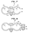
- This curved part 32 is sliding inside a first part 33 of a collar 34 having a second part 35 mounted around the mast 3 (FIG. 7).
- the central part of the collar 34 is crossed by a rod 36 of horizontal axis of a bolt 36a cooperating with a nut 37 outside the collar and separated from the latter by a washer 37a.
- the collar 34 comprises a single metal blade shaped to present at its ends two cylindrical bulges forming the parts 33 and 35.
- the end edges 38 and 39 of this blade are on the side of the part 33.
- the intermediate part, crossed by the rod 36 of the bolt 36a, has facing sections 40 and 41 which are substantially planar.
- the diameter R 1 of the part 35 and the external diameter of the mast 3 as well as the diameter R 2 of the part 33 and the external diameter of the curved end 32 of the arm 11 are such that before tightening the clearance between the mast 3 and the part 35 is less than the clearance between the curved end 32 and the part -33 of the collar. In this way, when the nut 37 is screwed onto the rod 36, the collar 34 is first blocked on the mast 3 before being blocked on the curved end 32.
- the nut 37 and the nuts cooperating with the bolts 14a, 15 and 31 are in a position such that the corresponding connections are joints and that the collar 34 can slide on the mast 3 and that the butt 32 at the end of the arm 11 can slide inside said collar 34.
- an approximate adjustment of the site is then carried out by sliding the collar 34 on the mast 3 between the flanges 4 and 5.
- the site is thus adjusted to within a few degrees.
- the nut 37 is tightened so that the collar is tightened on the mast 3 without, however, the butt 32 itself being blocked in the collar.
- the fine adjustment is obtained by sliding the stock 32 inside the part 33 of the collar 34.
- the reflector 1 can tilt around the axis of the bolts 14a and 15 and the axis 31 moves according to the circle 45 in broken lines in FIG. 1.
- the nut 37 is turned so that the collar is tightened on the stock 32 and the nuts on the support joints on the rear side of the reflector are also tightened so that the assembly is rigid.
- the two adjustments mentioned above allow the site to be varied by an angle of approximately 90 "or more.
- the fine adjustment, by actuation of the stock 32, allows, in the example, a variation of the site of the order of 20 °.
- the internal surface of the part 33 of the collar 34 has, instead of the cylindrical shape, substantially the shape of a torus segment which constitutes the part of the stock 32 housed in the part 33 of the collar 34.
- the embodiment shown in Figure 8 differs from that shown in Figure 7 in that the collar 34 1 , also formed by a single metal blade, has lips 46 and 47 extending part 33 1 and which are crossed by a bolt rod 48 cooperating with a nut 49 to perfect the tightening of this collar on the stock 32.
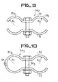
- the collar 34 2 shown in FIG. 9 is formed by two separate blades 50 and 51, the part 35 2 thus being open at its end, like the part 33 2 or the part 33 of FIG. 7.
- the collar 34 3 has two blades 52 and 53, but these are linked to each other by a hinge 54 in the part 35 3 opposite the rod 36 3 of bolt.
- the mast 3 is planted in the ground or is secured to a base.
Landscapes
- Aerials With Secondary Devices (AREA)
Abstract
Description
L'invention est relative à un support d'antenne destinée à capter des émissions, notamment de télévision, provenant d'un satellite géostationnaire ainsi qu'à l'ensemble formé par un tel support et son antenne.The invention relates to an antenna support intended to receive emissions, in particular from television, coming from a geostationary satellite as well as to the assembly formed by such a support and its antenna.
Les émissions de télévision seront, dans un proche avenir, transmises par l'intermédiaire d'un satellite géostationnaire. Ces émissions sont captées à l'aide d'un réflecteur qui diffère d'une antenne réceptrice habituelle, car il est en forme de paraboloide dont l'axe est dirigé vers le satellite.Television broadcasts will, in the near future, be transmitted via a geostationary satellite. These emissions are received using a reflector which differs from a usual receiving antenna, since it is in the form of a paraboloid whose axis is directed towards the satellite.
Le satellite étant géostationnaire le réflecteur parabolique doit avoir une position bien déterminée, réglée une fois pour toute. Le réglage qui doit être effectué lors de l'installation d'une telle antenne doit être simple afin qu'il puisse être mis en oeuvre par des personnes ne possédant pas de connaissances particulières en mécanique.The satellite being geostationary the parabolic reflector must have a well-determined position, adjusted once and for all. The adjustment which must be carried out during the installation of such an antenna must be simple so that it can be implemented by persons not having particular knowledge of mechanics.
Dans la demande de brevet européen n° 35930 du 27 février 1981 au nom de la demanderesse pour "support d'antenne de réception d'émissions d'un satellite géostationnaire, et antenne comportant un tel support" on a déjà proposé un support répondant à ces conditions. Ce support comprend un poteau de direction fixée par rapport au sol, notamment la direction verticale, qui peut tourner autour de son axe longitudinal pour régler l'azimut de l'antenne et un quadrilatère articulé dont un côté constitue une partie de l'antenne et un autre côté est une partie du poteau, la longueur de cette partie de poteau étant réglable et déterminant le site de l'antenne.In European patent application No. 35930 of February 27, 1981 in the name of the applicant for "antenna support for receiving transmissions from a geostationary satellite, and antenna comprising such a support", a support has already been proposed corresponding to These conditions. This support comprises a steering post fixed relative to the ground, in particular the vertical direction, which can rotate around its longitudinal axis to adjust the azimuth of the antenna and an articulated quadrilateral of which one side constitutes a part of the antenna and another side is a part of the pole, the length of this part of the pole being adjustable and determining the site of the antenna.
Un tel support est aisément réglable et peut être fabriqué à bon marché.Such a support is easily adjustable and can be manufactured inexpensively.
L'invention vise à perfectionner le support décrit dans cette demande de brevet de manière que son installation soit encore plus aisée sans en compliquer la fabrication.The invention aims to improve the support described in this patent application so that its installation is even easier without complicating its manufacture.
. Le support selon l'invention est donc du type de celui de la demande de brevet 35930, c'est-à-dire comprenant un quadrilatère ou autre polygône articulé dont un côté constitue une partie de l'antenne et un autre côté, de longueur réglable, est une partie du . poteau, et il est caractérisé en ce que l'un des autres côtés, se trouvant entre le poteau et l'antenne, a également une longueur réglable de façon à permettre un réglage supplémentaire du site de l'antenne.. The support according to the invention is therefore of the type of that of patent application 35930, that is to say comprising a quadrilateral or other articulated polygon of which one side constitutes a part of the antenna and another side, of length adjustable, is part of the. pole, and it is characterized in that one of the other sides, lying between the pole and the antenna, also has an adjustable length so as to allow additional adjustment of the antenna site.
De cette manière le réglage de la longueur du côté faisant partie du poteau peut constituer un réglage approché du site de l'antenne tandis que le réglage fin est obtenu par le réglage de la longueur de l'autre côté.In this way the adjustment of the length of the side forming part of the post can constitute an approximate adjustment of the antenna site while the fine adjustment is obtained by adjusting the length of the other side.
Dans une réalisation le côté de longueur réglable entre l'antenne et le poteau comprend un bras articulé par une de ses extrémités à l'antenne et, pour permettre le réglage de longueur, l'autre extrémité de ce bras est incurvée et coulissante dans une bague ou un collier solidaire du poteau. Ainsi le réglage fin est obtenu par un simple mouvement de coulissement.In one embodiment the side of adjustable length between the antenna and the post comprises an arm articulated by one of its ends to the antenna and, to allow the length adjustment, the other end of this arm is curved and sliding in a ring or necklace secured to the post. Thus the fine adjustment is obtained by a simple sliding movement.
De préférence ladite bague, dans laquelle coulisse l'extrémité incurvée du côté de longueur réglable, est également coulissante sur le poteau. Dans ce cas on peut prévoir le même moyen de commande pour bloquer la bague, ainsi en deux parties, respectivement sur le poteau et sur le bras à extrémité incurvée; pour que le réglage approché précède le réglage fin il est alors préférable que la bague double soit telle que le blocage sur le poteau soit obtenu avant le blocage sur l'extrémité incurvée. A cet effet le jeu entre la bague et le poteau est inférieur au jeu entre cette bague et l'extrémité incurvée.Preferably said ring, in which slides the curved end on the side of adjustable length, is also sliding on the post. In this case, the same control means can be provided to block the ring, thus in two parts, respectively on the post and on the arm with curved end; so that the approximate adjustment precedes the fine adjustment it is then preferable for the double ring to be such that the blocking on the post is obtained before the blocking on the curved end. For this purpose the clearance between the ring and the post is less than the clearance between this ring and the curved end.
L'invention vise également le cas où seul le côté entre le poteau et le réflecteur est de longueur variable, le réglage du site n'étant ainsi obtenu que par le réglage de la longueur de ce côté.The invention also relates to the case where only the side between the post and the reflector is of variable length, the adjustment of the site being thus obtained only by adjusting the length of this side.
Ainsi, selon un autre de ses aspects, l'invention vise un support d'antenne comprenant un mât de direction fixée, notamment verticale, par rapport au sol, et pouvant tourner autour de son axe longitudinal pour régler l'azimut de l'antenne et un polygône, tel qu'un quadrilatère, articulable dont un côté constitue une partie de l'antenne et un autre côté est une partie du poteau, ce support étant caractérisé en ce qu'un côté de ce polygône entre le mât et l'antenne a une longueur réglable afin de permettre un réglage du site de l'antenne grâce à une extrémité incurvée coulissant dans un collier solidaire du mât.Thus, according to another of its aspects, the invention relates to an antenna support comprising a fixed, especially vertical, steering mast relative to the ground, and which can rotate about its axis. longitudinal to adjust the azimuth of the antenna and a polygon, such as a quadrilateral, articulated of which one side constitutes a part of the antenna and another side is a part of the pole, this support being characterized in that a side of this polygon between the mast and the antenna has an adjustable length to allow adjustment of the antenna site thanks to a curved end sliding in a collar secured to the mast.
D'autres caractéristiques et avantages de l'invention apparaîtront avec la description de certains de ses modes de réalisation, celle-ci étant effectuée en se référant aux dessins ci-annexés sur lesquels :
- - la figure 1 est une vue schématique de l'ensemble d'une antenne et de son support selon l'invention,
- - la figure 2 est une vue d'un étrier faisant partie du support de la figure 1,
- - la figure 3 est une vue selon la flèche f de la figure 2,
- - la figure 4 montre le sommet du poteau du support de la figure 1,
- - la figure 5 est une coupe selon la ligne 5-5 de la figure 4,
- - la figure 6 est une vue en coupe montrant l'assemblage du sommet du poteau du support avec l'étrier représenté sur les figures 2 et 3,
- - la figure 7 montre un collier faisant partie du support de la figure 1, et
- - les figures 8, 9 et 10 représentent des variantes du collier de la figure 7.
- FIG. 1 is a schematic view of the assembly of an antenna and of its support according to the invention,
- FIG. 2 is a view of a stirrup forming part of the support of FIG. 1,
- FIG. 3 is a view along the arrow f in FIG. 2,
- FIG. 4 shows the top of the support post of FIG. 1,
- FIG. 5 is a section along line 5-5 of FIG. 4,
- FIG. 6 is a sectional view showing the assembly of the top of the support post with the stirrup shown in FIGS. 2 and 3,
- FIG. 7 shows a collar forming part of the support of FIG. 1, and
- - Figures 8, 9 and 10 show variants of the collar of Figure 7.
L'antenne 1 (figure 1) est destinée à capter des émissions de télévision provenant d'un satellite géostationnaire. Elle comporte un réflecteur en forme de paraboloide d'axe 2 dirigé vers le satellite. Ce réflecteur réfléchit les ondes sur un capteur (non représenté) relié par câble à un ou plusieurs récepteurs de télévision.The antenna 1 (Figure 1) is intended to receive television broadcasts from a geostationary satellite. It includes a reflector in the shape of an
Le satellite émetteur ou réémetteur ayant une position fixe par rapport à la terre, le réflecteur 1 garde toujours la même position lorsqu'il doit capter les émissions provenant d'un satellite déterminé. L'orientation de l'axe 2 est donc effectuée une fois pour toute au cours de l'installation de l'antenne. Ce réglage de la direction de l'axe 2 doit cependant pouvoir être modifié pour tenir compte d'un éventuel changement de position du satellite ou du remplacement de ce satellite par un autre.The transmitting or re-transmitting satellite having a fixed position relative to the earth, the
Ce réglage doit pouvoir être effectué de façon aisée. C'est ce que permet le support selon l'invention.This adjustment must be easy to make. This is what the support according to the invention allows.
Dans l'exemple le support comprend un mât ou poteau vertical 3 constitué par un tube métallique de section circulaire fixé par deux brides respectivement inférieure 4 et supérieure 5 à un mur 6 ou un autre élément fixe. L'extrémité supérieure 7 du mât 3 est en saillie au-dessus de la bride 5.In the example, the support comprises a vertical mast or
Les brides 4 et 5 sont pourvues de boulons et d'écrous de serrage 8 pour maintenir le mât 3 dans ces brides. Ainsi, avant le serrage, le mât peut tourner autour de son axe vertical 3a pour régler l'azimut du réflecteur 1.The
Le mât 3 est raccordé à un raidisseur 9 solidaire de la face arrière du réflecteur 1 par l'intermédiaire d'un bras 10 incliné à environ 45° par rapport à l'horizontale et en forme d'étrier et d'un bras tubulaire 11. Ces deux bras sont articulés au raidisseur 9.The
Le bras 10 a la forme générale d'un étrier à deux branches 12 et 13 qui divergent à partir d'une base 14 (figure 2) et se terminent cependant par des extrémités parallèles 12a et 13a traversées par des tiges de boulons 14a et 15 dont les axes sont en prolongement et qui traversent également des branches 16 et 17 d'équerres dont les autres branches sont fixées à, et appliquées contre, la face arrière du raidisseur 9. De cette manière lorsque les écrous coopérant avec les boulons 14a et 15 ne sont pas serrés les branches 12 et 13 sont articulées aux branches 16 et 17 des équerres fixées au réflecteur 1.The
La base 14, dont la longueur test supérieure au diamètre du tube 3, est introduite dans une fente 19 (figures 4 et 5), inclinée à 43° par rapport à l'horizontale, que présente l'extrémité supérieure 7 du mât 3. Les extrémités 20 et 21 de cette fente sont, dans l'exemple, diamétralement opposées.The
La partie centrale de la basé 14 comporte une fente 22 en forme d'arc de cercle limitant une patte ou languette 23 rattachée au reste de la base 14 selon la ligne fictive 24 reliant les extrémités de la fente 22.The central part of the
Une arête 25 de la base 14 présente deux échancrures 26 et 27 dans lesquelles pénètrent les parties de la paroi du tube 3 avoisinant les extrémités 20 et 21 de la fente 19. De cette manière le bras 10 a une position bien précise par rapport au mât.An
La fixation de l'étrier 10 au mât est obtenue en écartant de la base 14, à l'opposé des branches 12 et 13, la languette 23 après introduction de la base dans la fente 19 (figure 6). Dans ces conditions l'extrémité 28 opposée à la ligne 24 est en appui contre la surface interne du tube 3. La fixation du bras 10 au tube 3 est ainsi effectuée de façon particulièrement simple à l'aide d'une languette découpée.The fixing of the
Pour écarter la languette 23 du plan de la base 14 on introduit un outil par l'ouverture supérieure 7a du tube et on exerce une poussée verticale dirigée vers le bas.To separate the
Le bras 11 se termine par une fente dans laquelle est introduite une branche 30 en saillie d'une embase appliquée contre, et fixée à, la face externe du raidisseur 9. La tige filetée d'un boulon 31 traverse cette extrémité du bras 11 et la branche 30. Ainsi, avant serrage de l'écrou coopérant avec le boulon 31, le bras 11 est articulé à la branche 30 et donc au réflecteur 1.The
A son extrémité opposée le bras 11, qui est comme le mât 3 constitué par un tube, se termine par une partie incurvée 32 constituant dans l'exemple un arc de cercle dont la concavité est tournée vers le réflecteur.At its opposite end, the
Cette partie incurvée 32 est coulissante à l'intérieur d'une première partie 33 d'un collier 34 présentant une deuxième partie 35 montée autour du mât 3 (figure 7).This
La partie centrale du collier 34 est traversée par une tige 36 d'axe horizontal d'un boulon 36a coopérant avec un écrou 37 à l'extérieur du collier et séparé de ce dernier par une rondelle 37a.The central part of the
Dans l'exemple représenté sur la figure 7 le collier 34 comprend une unique lame métallique conformée pour présenter à ses extrémités deux renflements cylindriques formant les parties 33 et 35. Les arêtes d'extrémité 38 et 39 de cette lame sont du côté de la partie 33. La partie intermédiaire, traversée par la tige 36 du boulon 36a, présente des sections 40 et 41 en regard qui sont sensiblement planes.In the example shown in Figure 7 the
Le diamètre R1 de la partie 35 et le diamètre externe du mât 3 ainsi que le diamètre R2 de la partie 33 et le diamètre externe de l'extrémité recourbée 32 du bras 11 sont tels qu'avant serrage le jeu entre le mât 3 et la partie 35 est inférieur au jeu entre l'extrémité recourbée 32 et la partie -33 du collier. De cette manière lorsque l'écrou 37 est vissé sur la tige 36 le collier 34 est d'abord bloqué sur le mât 3 avant d'être bloqué sur l'extrémité incurvée 32.The diameter R 1 of the
Le réglage s'effectue de la façon suivante :
- Après réglage de l'azimut par rotation du mât 3 autour de son axe vertical 3a les brides 4
et 5 sont serrées sur le mât 3 grâce aux boulons et écrous 8.
- After adjusting the azimuth by rotating the
mast 3 around its vertical axis 3a, theflanges 4 and 5 are tightened on themast 3 using the bolts and nuts 8.
Pour le réglage du site l'écrou 37 ainsi que les écrous coopérant avec les boulons 14a, 15 et 31 sont dans une position telle que les liaisons correspondantes sont des articulations et que le collier 34 peut coulisser sur le mât 3 et que la crosse 32 à l'extrémité du bras 11 peut coulisser à l'intérieur dudit collier 34.For site adjustment, the
On effectue alors en premier lieu un réglage approché du site en faisant coulisser le collier 34 sur le mât 3 entre les brides 4 et 5. Le site est ainsi réglé à quelques degrés près. Dans cette condition on serre l'écrou 37 de façon que le collier soit serré sur le mât 3 sans cependant que la crosse 32 soit elle-même bloquée dans le collier. Le réglage fin est obtenu en faisant coulisser la crosse 32 à l'intérieur de la partie 33 du collier 34. Dans cette condition le réflecteur 1 peut basculer autour de l'axe des boulons 14a et 15 et l'axe 31 se déplace selon le cercle 45 en traits interrompus sur la figure 1. Lorsque le réglage convenable a été obtenu l'écrou 37 est tourné de manière que le collier soit serré sur la crosse 32 et les écrous aux articulations du support à la face arrière du réflecteur sont également serrés de manière que l'ensemble soit rigide.First, an approximate adjustment of the site is then carried out by sliding the
Les deux réglages mentionnés ci-dessus permettent de faire varier le site d'un angle d'environ 90" ou plus. Le réglage fin, par actionnement de la crosse 32, autorise, dans l'exemple, une variation du site de l'ordre de 20°.The two adjustments mentioned above allow the site to be varied by an angle of approximately 90 "or more. The fine adjustment, by actuation of the
En variante la surface interne de la partie 33 du collier 34 a, au lieu de la forme cylindrique, sensiblement la forme d'un segment de tore que constitue la partie de la crosse 32 logée dans la partie 33 du collier 34.As a variant, the internal surface of the
Le mode de réalisation représenté sur la figure 8 se distingue de celui représenté sur la figure 7 par le fait que le collier 341, également formé par une seule lame métallique, présente des lèvres 46 et 47 prolongeant la partie 331 et qui sont traversées par une tige 48 de boulon coopérant avec un écrou 49 pour parfaire le serrage de ce collier sur la crosse 32.The embodiment shown in Figure 8 differs from that shown in Figure 7 in that the
Le collier 342 représenté sur la figure 9 est formé de deux lames séparées 50 et 51, la partie 352 étant ainsi ouverte à son extrémité, comme la partie 332 ou la partie 33 de la figure 7.The
Dans l'exemple de la figure 10 le collier 343 présente deux lames 52 et 53 mais celles-ci sont liées l'une à l'autre par une articulation 54 dans la partie 353 à l'opposé de la tige 363 de boulon.In the example of FIG. 10, the
En variante le mât 3 est planté dans le sol ou est solidaire d'un socle.As a variant, the
Claims (21)
Applications Claiming Priority (2)
| Application Number | Priority Date | Filing Date | Title |
|---|---|---|---|
| FR8119077A FR2514570A1 (en) | 1981-10-09 | 1981-10-09 | ANTENNA CARRIER FOR CAPTURING TELEVISION TRANSMISSIONS FROM A GEOSTATIONARY SATELLITE AND ASSEMBLY FORMED BY SUCH A SUPPORT AND ITS ANTENNA |
| FR8119077 | 1981-10-09 |
Publications (1)
| Publication Number | Publication Date |
|---|---|
| EP0077250A1 true EP0077250A1 (en) | 1983-04-20 |
Family
ID=9262911
Family Applications (1)
| Application Number | Title | Priority Date | Filing Date |
|---|---|---|---|
| EP82401799A Withdrawn EP0077250A1 (en) | 1981-10-09 | 1982-10-01 | Mount for an antenna for satellite television reception and unit formed by such a support with its antenna |
Country Status (3)
| Country | Link |
|---|---|
| EP (1) | EP0077250A1 (en) |
| AU (1) | AU8925582A (en) |
| FR (1) | FR2514570A1 (en) |
Cited By (2)
| Publication number | Priority date | Publication date | Assignee | Title |
|---|---|---|---|---|
| FR2536591A1 (en) * | 1982-11-23 | 1984-05-25 | Thomson Brandt | GEOSTATIONARY SATELLITE TELECOMMUNICATION ANTENNA SUPPORT AND ASSEMBLY FORMED BY SUCH A SUPPORT AND ITS ANTENNA |
| US5402139A (en) * | 1991-02-21 | 1995-03-28 | Sony Corporation | Antenna and mounting arrangement |
Families Citing this family (1)
| Publication number | Priority date | Publication date | Assignee | Title |
|---|---|---|---|---|
| CN111082199B (en) * | 2020-03-09 | 2021-04-23 | 祁爱军 | Satellite pot with cleaning function |
Citations (5)
| Publication number | Priority date | Publication date | Assignee | Title |
|---|---|---|---|---|
| US3623115A (en) * | 1968-12-07 | 1971-11-23 | Telefunken Patent | Directional antenna |
| DE2204448A1 (en) * | 1972-01-31 | 1973-08-09 | Rohde & Schwarz | DEVICE FOR BIAXIAL PIVOTING OF THE REFLECTOR OF A DIRECTIONAL ANTENNA, IN PARTICULAR OF A MOBILE SATELLITE TRACKING SYSTEM |
| US4126865A (en) * | 1975-11-11 | 1978-11-21 | The Secretary Of State For Defence In Her Britannic Majesty's Government Of The United Kingdom Of Great Britain And Northern Ireland | Satellite tracking dish antenna |
| FR2471058A3 (en) * | 1979-12-07 | 1981-06-12 | Thomson Brandt | Antenna support for TV reception via satellite - comprises curved tube with graduations onto which slides collar with blocking mechanism and antenna attachment |
| EP0035930A1 (en) * | 1980-03-11 | 1981-09-16 | Société S E R E L | Mounting for an antenna for the reception of signals from a geostationary satellite, and antenna comprising such a mounting |
-
1981
- 1981-10-09 FR FR8119077A patent/FR2514570A1/en active Granted
-
1982
- 1982-10-01 EP EP82401799A patent/EP0077250A1/en not_active Withdrawn
- 1982-10-11 AU AU89255/82A patent/AU8925582A/en not_active Abandoned
Patent Citations (5)
| Publication number | Priority date | Publication date | Assignee | Title |
|---|---|---|---|---|
| US3623115A (en) * | 1968-12-07 | 1971-11-23 | Telefunken Patent | Directional antenna |
| DE2204448A1 (en) * | 1972-01-31 | 1973-08-09 | Rohde & Schwarz | DEVICE FOR BIAXIAL PIVOTING OF THE REFLECTOR OF A DIRECTIONAL ANTENNA, IN PARTICULAR OF A MOBILE SATELLITE TRACKING SYSTEM |
| US4126865A (en) * | 1975-11-11 | 1978-11-21 | The Secretary Of State For Defence In Her Britannic Majesty's Government Of The United Kingdom Of Great Britain And Northern Ireland | Satellite tracking dish antenna |
| FR2471058A3 (en) * | 1979-12-07 | 1981-06-12 | Thomson Brandt | Antenna support for TV reception via satellite - comprises curved tube with graduations onto which slides collar with blocking mechanism and antenna attachment |
| EP0035930A1 (en) * | 1980-03-11 | 1981-09-16 | Société S E R E L | Mounting for an antenna for the reception of signals from a geostationary satellite, and antenna comprising such a mounting |
Non-Patent Citations (1)
| Title |
|---|
| FUNKSCHAU, vol. 52, no. 14, juillet 1980, pages 45-48, Munich (DE); * |
Cited By (3)
| Publication number | Priority date | Publication date | Assignee | Title |
|---|---|---|---|---|
| FR2536591A1 (en) * | 1982-11-23 | 1984-05-25 | Thomson Brandt | GEOSTATIONARY SATELLITE TELECOMMUNICATION ANTENNA SUPPORT AND ASSEMBLY FORMED BY SUCH A SUPPORT AND ITS ANTENNA |
| EP0112205A1 (en) * | 1982-11-23 | 1984-06-27 | Thomson-Brandt | Support for an antenna for satellite broadcast reception, and combination of the support and its antenna |
| US5402139A (en) * | 1991-02-21 | 1995-03-28 | Sony Corporation | Antenna and mounting arrangement |
Also Published As
| Publication number | Publication date |
|---|---|
| AU8925582A (en) | 1983-04-14 |
| FR2514570B1 (en) | 1983-12-02 |
| FR2514570A1 (en) | 1983-04-15 |
Similar Documents
| Publication | Publication Date | Title |
|---|---|---|
| EP0194951B1 (en) | Device to adjust the angle of a roller blind or the like | |
| FR2815477A1 (en) | Supports for more than one relay antennas of a cellular telecommunication radio on a mast and device to tune the orientation of such an antenna. | |
| EP2248717A1 (en) | Cycle arm with adjustable length | |
| FR2945022A1 (en) | ADJUSTABLE TILT CYCLE POTENTIAL | |
| EP0035930B1 (en) | Mounting for an antenna for the reception of signals from a geostationary satellite, and antenna comprising such a mounting | |
| EP0077250A1 (en) | Mount for an antenna for satellite television reception and unit formed by such a support with its antenna | |
| FR2756334A1 (en) | Fastening device e.g. for hook of vehicle sun visor | |
| WO2004095630A1 (en) | Antenna mounting enabling fine adjustment of the orientation of the antenna | |
| EP0114543A2 (en) | Omnidirectional orientating device for an antenna | |
| EP1050919A1 (en) | Device for supporting and adjusting a radiocommunication antenna | |
| FR2898180A1 (en) | Wave receiving and transmitting telecommunication antenna suspending device for building, has crank integrated in rotation with one part of arm and actuated by actuator articulated on support unit, where actuator controls rotation of pole | |
| EP0364974A2 (en) | Antenna support adjustable in azimuth and elevation | |
| WO2004109845A1 (en) | Antenna mount for fine adjustment of the antenna azimuth orientation | |
| EP4194647A1 (en) | Post for mounting a fence panel | |
| FR2595510A1 (en) | Reception antenna support | |
| FR2823014A1 (en) | DEVICE FOR MOUNTING AN ANTENNA ON A WALL WITH ANTENNA SUSPENSION ALONG THIS WALL | |
| EP0112205A1 (en) | Support for an antenna for satellite broadcast reception, and combination of the support and its antenna | |
| FR2842653A1 (en) | Antenna support mast, has antenna support arm pivotally mounted on vertical post via adjustable length connection | |
| EP1813740A1 (en) | Shelter | |
| FR2612968A1 (en) | ASSEMBLY FOR THE CONFECTION OF BUILDING WALLS | |
| FR3092895A1 (en) | EQUIPMENT SUSPENSION DEVICE FROM A PLATFORM | |
| FR2913285A1 (en) | Supplementary microwave frequency head adding device for satellite reception antenna, has fixing unit to fix supplementary microwave frequency head directly to microwave frequency head of antenna, and to hold microwave frequency head | |
| EP4455497A1 (en) | Continuously adjustable connecting rod and method for mounting the adjustable connecting rod | |
| FR2516576A1 (en) | Bracket for fitting gutter to roof - has cane and jaw parts bolted together with swivel joint | |
| FR2689611A1 (en) | Device for mounting a motor vehicle headlight part |
Legal Events
| Date | Code | Title | Description |
|---|---|---|---|
| PUAI | Public reference made under article 153(3) epc to a published international application that has entered the european phase |
Free format text: ORIGINAL CODE: 0009012 |
|
| AK | Designated contracting states |
Designated state(s): BE CH DE GB IT LI NL SE |
|
| 17P | Request for examination filed |
Effective date: 19830427 |
|
| STAA | Information on the status of an ep patent application or granted ep patent |
Free format text: STATUS: THE APPLICATION IS DEEMED TO BE WITHDRAWN |
|
| 18D | Application deemed to be withdrawn |
Effective date: 19850326 |
|
| RIN1 | Information on inventor provided before grant (corrected) |
Inventor name: REPUSSARD, JEAN-YVES |