EP0077335B1 - Isolierelement, sowie verfahren zu dessen herstellung und verwendung - Google Patents
Isolierelement, sowie verfahren zu dessen herstellung und verwendung Download PDFInfo
- Publication number
- EP0077335B1 EP0077335B1 EP82901026A EP82901026A EP0077335B1 EP 0077335 B1 EP0077335 B1 EP 0077335B1 EP 82901026 A EP82901026 A EP 82901026A EP 82901026 A EP82901026 A EP 82901026A EP 0077335 B1 EP0077335 B1 EP 0077335B1
- Authority
- EP
- European Patent Office
- Prior art keywords
- insulation
- metal foil
- foam plastic
- parts
- insulation element
- Prior art date
- Legal status (The legal status is an assumption and is not a legal conclusion. Google has not performed a legal analysis and makes no representation as to the accuracy of the status listed.)
- Expired
Links
Images


Classifications
-
- F—MECHANICAL ENGINEERING; LIGHTING; HEATING; WEAPONS; BLASTING
- F17—STORING OR DISTRIBUTING GASES OR LIQUIDS
- F17C—VESSELS FOR CONTAINING OR STORING COMPRESSED, LIQUEFIED OR SOLIDIFIED GASES; FIXED-CAPACITY GAS-HOLDERS; FILLING VESSELS WITH, OR DISCHARGING FROM VESSELS, COMPRESSED, LIQUEFIED, OR SOLIDIFIED GASES
- F17C13/00—Details of vessels or of the filling or discharging of vessels
- F17C13/001—Thermal insulation specially adapted for cryogenic vessels
-
- F—MECHANICAL ENGINEERING; LIGHTING; HEATING; WEAPONS; BLASTING
- F16—ENGINEERING ELEMENTS AND UNITS; GENERAL MEASURES FOR PRODUCING AND MAINTAINING EFFECTIVE FUNCTIONING OF MACHINES OR INSTALLATIONS; THERMAL INSULATION IN GENERAL
- F16L—PIPES; JOINTS OR FITTINGS FOR PIPES; SUPPORTS FOR PIPES, CABLES OR PROTECTIVE TUBING; MEANS FOR THERMAL INSULATION IN GENERAL
- F16L59/00—Thermal insulation in general
- F16L59/12—Arrangements for supporting insulation from the wall or body insulated, e.g. by means of spacers between pipe and heat-insulating material; Arrangements specially adapted for supporting insulated bodies
- F16L59/13—Resilient supports
-
- F—MECHANICAL ENGINEERING; LIGHTING; HEATING; WEAPONS; BLASTING
- F17—STORING OR DISTRIBUTING GASES OR LIQUIDS
- F17C—VESSELS FOR CONTAINING OR STORING COMPRESSED, LIQUEFIED OR SOLIDIFIED GASES; FIXED-CAPACITY GAS-HOLDERS; FILLING VESSELS WITH, OR DISCHARGING FROM VESSELS, COMPRESSED, LIQUEFIED, OR SOLIDIFIED GASES
- F17C2201/00—Vessel construction, in particular geometry, arrangement or size
- F17C2201/01—Shape
- F17C2201/0104—Shape cylindrical
- F17C2201/0109—Shape cylindrical with exteriorly curved end-piece
-
- F—MECHANICAL ENGINEERING; LIGHTING; HEATING; WEAPONS; BLASTING
- F17—STORING OR DISTRIBUTING GASES OR LIQUIDS
- F17C—VESSELS FOR CONTAINING OR STORING COMPRESSED, LIQUEFIED OR SOLIDIFIED GASES; FIXED-CAPACITY GAS-HOLDERS; FILLING VESSELS WITH, OR DISCHARGING FROM VESSELS, COMPRESSED, LIQUEFIED, OR SOLIDIFIED GASES
- F17C2201/00—Vessel construction, in particular geometry, arrangement or size
- F17C2201/01—Shape
- F17C2201/0128—Shape spherical or elliptical
-
- F—MECHANICAL ENGINEERING; LIGHTING; HEATING; WEAPONS; BLASTING
- F17—STORING OR DISTRIBUTING GASES OR LIQUIDS
- F17C—VESSELS FOR CONTAINING OR STORING COMPRESSED, LIQUEFIED OR SOLIDIFIED GASES; FIXED-CAPACITY GAS-HOLDERS; FILLING VESSELS WITH, OR DISCHARGING FROM VESSELS, COMPRESSED, LIQUEFIED, OR SOLIDIFIED GASES
- F17C2201/00—Vessel construction, in particular geometry, arrangement or size
- F17C2201/03—Orientation
- F17C2201/035—Orientation with substantially horizontal main axis
-
- F—MECHANICAL ENGINEERING; LIGHTING; HEATING; WEAPONS; BLASTING
- F17—STORING OR DISTRIBUTING GASES OR LIQUIDS
- F17C—VESSELS FOR CONTAINING OR STORING COMPRESSED, LIQUEFIED OR SOLIDIFIED GASES; FIXED-CAPACITY GAS-HOLDERS; FILLING VESSELS WITH, OR DISCHARGING FROM VESSELS, COMPRESSED, LIQUEFIED, OR SOLIDIFIED GASES
- F17C2203/00—Vessel construction, in particular walls or details thereof
- F17C2203/03—Thermal insulations
- F17C2203/0304—Thermal insulations by solid means
- F17C2203/0308—Radiation shield
- F17C2203/032—Multi-sheet layers
-
- F—MECHANICAL ENGINEERING; LIGHTING; HEATING; WEAPONS; BLASTING
- F17—STORING OR DISTRIBUTING GASES OR LIQUIDS
- F17C—VESSELS FOR CONTAINING OR STORING COMPRESSED, LIQUEFIED OR SOLIDIFIED GASES; FIXED-CAPACITY GAS-HOLDERS; FILLING VESSELS WITH, OR DISCHARGING FROM VESSELS, COMPRESSED, LIQUEFIED, OR SOLIDIFIED GASES
- F17C2203/00—Vessel construction, in particular walls or details thereof
- F17C2203/03—Thermal insulations
- F17C2203/0304—Thermal insulations by solid means
- F17C2203/0329—Foam
-
- F—MECHANICAL ENGINEERING; LIGHTING; HEATING; WEAPONS; BLASTING
- F17—STORING OR DISTRIBUTING GASES OR LIQUIDS
- F17C—VESSELS FOR CONTAINING OR STORING COMPRESSED, LIQUEFIED OR SOLIDIFIED GASES; FIXED-CAPACITY GAS-HOLDERS; FILLING VESSELS WITH, OR DISCHARGING FROM VESSELS, COMPRESSED, LIQUEFIED, OR SOLIDIFIED GASES
- F17C2205/00—Vessel construction, in particular mounting arrangements, attachments or identifications means
- F17C2205/01—Mounting arrangements
- F17C2205/0153—Details of mounting arrangements
- F17C2205/018—Supporting feet
-
- F—MECHANICAL ENGINEERING; LIGHTING; HEATING; WEAPONS; BLASTING
- F17—STORING OR DISTRIBUTING GASES OR LIQUIDS
- F17C—VESSELS FOR CONTAINING OR STORING COMPRESSED, LIQUEFIED OR SOLIDIFIED GASES; FIXED-CAPACITY GAS-HOLDERS; FILLING VESSELS WITH, OR DISCHARGING FROM VESSELS, COMPRESSED, LIQUEFIED, OR SOLIDIFIED GASES
- F17C2221/00—Handled fluid, in particular type of fluid
- F17C2221/03—Mixtures
- F17C2221/032—Hydrocarbons
- F17C2221/033—Methane, e.g. natural gas, CNG, LNG, GNL, GNC, PLNG
-
- F—MECHANICAL ENGINEERING; LIGHTING; HEATING; WEAPONS; BLASTING
- F17—STORING OR DISTRIBUTING GASES OR LIQUIDS
- F17C—VESSELS FOR CONTAINING OR STORING COMPRESSED, LIQUEFIED OR SOLIDIFIED GASES; FIXED-CAPACITY GAS-HOLDERS; FILLING VESSELS WITH, OR DISCHARGING FROM VESSELS, COMPRESSED, LIQUEFIED, OR SOLIDIFIED GASES
- F17C2223/00—Handled fluid before transfer, i.e. state of fluid when stored in the vessel or before transfer from the vessel
- F17C2223/01—Handled fluid before transfer, i.e. state of fluid when stored in the vessel or before transfer from the vessel characterised by the phase
- F17C2223/0146—Two-phase
- F17C2223/0153—Liquefied gas, e.g. LPG, GPL
- F17C2223/0161—Liquefied gas, e.g. LPG, GPL cryogenic, e.g. LNG, GNL, PLNG
-
- F—MECHANICAL ENGINEERING; LIGHTING; HEATING; WEAPONS; BLASTING
- F17—STORING OR DISTRIBUTING GASES OR LIQUIDS
- F17C—VESSELS FOR CONTAINING OR STORING COMPRESSED, LIQUEFIED OR SOLIDIFIED GASES; FIXED-CAPACITY GAS-HOLDERS; FILLING VESSELS WITH, OR DISCHARGING FROM VESSELS, COMPRESSED, LIQUEFIED, OR SOLIDIFIED GASES
- F17C2223/00—Handled fluid before transfer, i.e. state of fluid when stored in the vessel or before transfer from the vessel
- F17C2223/03—Handled fluid before transfer, i.e. state of fluid when stored in the vessel or before transfer from the vessel characterised by the pressure level
- F17C2223/033—Small pressure, e.g. for liquefied gas
Definitions
- the present Invention relates to an insulation element, preferably for thermal insulation of tanks for liquified gases or the like, comprising at least a first and a second substantially sheet- formed layer of foam plastic which are attached to a flexible reinforcement layer therebetween, said element at least on one side being coated with a metal foil or the like and being pliable in at least one part to be able to attain a curved form.
- Such insulation elements are currently being used in the form of long bars for insulating spherical tanks for LNG.
- the bars are joined together to a long string which is wound on the tank so as to form two approximate semispherical continuous insulation bodies.
- the string of insulation elements is on its external side provided with aluminum foil acting as vapour barrier and protecting the insulating material against external damage.
- Such spherical tanks are often supported by a cylindrical skirt in the equatorial area. Near the transition between sphere and skirt a very narrow space is formed, which is difficult to cover with insulating material. Furthermore, substantial thermally dependent movements will occur at this point because the spherical tank contracts relatively much during cooling while the skirt generally remains at ambient temperature. Therefore, cracks are prone to occur in the insulation near the transition between tank and skirt.
- the invention aims at providing an insulation element which will facilitate insulating the above-mentioned critical areas and concurrently avoid the danger of crack formation and other reduction of the properties of the insulation.
- This, according to the invention is obtained by an insulation element of the type defined above, it being characterized in that the metal foil or the like is only partly fixed to the element, the loose part or parts of the metal foil being located on the areas which after binding form a concave shape.
- the metal foil may be fixed to those parts of the element which are essentially straight after bending.
- the metal foil will provide relatively high stiffness in these parts of the element and thus provide good control of the part or parts of the element to be bent.
- the final form of the element in installed condition may therefore be more closely determined, thus making is simpler to join such elements side by side to a tarqer y nii,
- the metal foil may lie double in at least one of the parts which are curved after bending. This will make it easier to bend the element strongly without wrinkling or damaging the metal foil.
- polystyrene is a material which is very well suited as cryogenic insulation, but which in non-treated condition is too brittle and stiff to be subjected to the bending contemplated by the invention without rupturing.
- the two layers of foam plastic material may advantageously be staggered with respect to each other in at least one direction, preferably transversely of the main dimension of the element.
- this form will provide overlapping between the flexible reinforcement layers of the elements, so that these may be glued to each other and form a continuous reinforcement layer through the elements.
- the invention also relates to a method for manufacturing an insulation element, where at least a first and a second layer of foam plastic is attached to a flexible reinforcement layer therebetween and is coated by a metal foil or the like, whereupon the element may be bent to curved form.
- the metal foil is fixed to the respective foam plastic layer substantially only in those parts which are not to be bent. Those parts of the foam plastic to which the metal foil is fixed, become stiff enough as compared to the remaining parts that the element automatically will bend in these remaining parts when it is subjected to a bending moment. Therefore, one obtains good control of the final shape of the element without having to use complicated manufacturing methods or apparatus to effect the bending.
- the element may advantageously be provided with a permanently curved form by holding it in bent condition during a predetermined time period sufficient to cause permanent deformation of the foam plastic material.
- a permanently curved form by holding it in bent condition during a predetermined time period sufficient to cause permanent deformation of the foam plastic material.
- the invention also relates to the use of an insulation element of the type described above for thermally insulating a tank in the area of its support.
- Such use of the insulation is particularly advantageous in insulating relatively large tanks for cryogenic liquids due to the great ability of the insulation element to accommodate relative movements without being damaged.
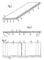
- the insulation element shown in Fig. 1 comprises two generally sheet-like layers 1 and 2 of foam plastic, which are glued to a flexible reinforcement layer 3 therebetween.
- the foam plastic has a closed cell structure and is preferably constituted by polystyrene which has been flexibilized in the longitudinal direction of the element.
- the foam plastic layer 1 has chamferred longitudinal edges and is shifted somewhat with respect to the foam plastic layer 2, so that the longitudinal edges of the element will have a stepped shape which facilitates overlapping joints between insulation elements placed side by side.
- the reinforcement layer 3 extends all the way out to the longitudinal edges of the insulation element, so that the exposed parts 3', 3" may be glued directly to corresponding parts of adjacent insulation elements and thus provide a continuous reinforcement layer through all the elements.
- the foam plastic layer 2 is on its outwardly facing side provided with an aluminum foil 4 which is glued to the foam plastic on the major part of its area.
- the aluminum foil 4 is split in the middle and has four parts 5, 6, 7 and 8, which limits are indicated in broken lines in Fig. 3, which are not glued to the foam plastic layer 2. The parts 6 and 7 thus form loose flaps of the aluminum foil 4.
- Fig. 4 shows the insulation element in bent condition. This condition is obtained by gripping the element by its ends, which then are bent towards each other on the aluminum foil side, as indicated with arrows in Fig. 2.
- the element By holding the element in bent condition for a suitable period of time, for instance in a jig overnight, the element will be subjected to a permanent deformation and therefore retain its U-shape after being taken out of the jig.
- the loose flaps 6, 7 of the aluminum foil have overlapped due to the compression of the foam plastic layer 2.
- the overlapping parts of the loose flaps 6, 7 are then glued to each other in order for the aluminum foil 4 to form a continuous entity in the finished bent insulation element.
- Fig. 5 shows the bent insulation element installed in a space being limited by parallel surfaces.
- the element is also bent in those places where the parts 5 and 8 of the aluminum foil 4 are not fixed to the foam plastic layer 2.
- the lacking connection between the aluminum foil and the foam plastic makes the element particularly flexible at these points making it bend there rather than at some other point of the legs of the U. The element will be able to accommodate such movements as indicated with arrows in the figure.
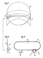
- Fig. 6 shows the element installed between two surfaces which extend at an angle. Also in this case the arrows indicate the relative movements the element can accommodate.
- Fig. 7 is shown how the insulation element according to the invention is installed in the same way as in Fig. 6 in order to close the space 9 between a spherical tank 4 and its supporting skirt 11.
- Fig. 8 shows how two rows of insulation elements according to the invention may be used in order to provide especially good insulation of this part of the tank structure. It will appear from these figures that in use of insulation elements according to the invention, one does not have to work in the uppermost part of the narrow space 9 between tank and skirt. The invention thus provides substantial simplification and rationalization of the insulation work and concurrently gives a more reliable and effective resu It.
- Fig. 9 shows a generally cylindrical, lying tank 12 resting on fixed supports, for example saddle supports 13 and 14. Due to the thermally dependent movements of the tank with respect to the foundation, the tank is supported slidably on the support 14, as indicated by the arrow. In order that the insulation 15 of the tank is not damaged at the support 14 during such movements, elements 16 according to the invention are installed between the tank insulation 15 and the support insulation 17.
- Figs. 10 and 11 show the invention used in insulating pipes where relative movements are to be expected.
- the pipe is designated 18 and the insulation 19.
- a flexible ring consisting of elements 20 according to the invention is introduced.
- Fig. 11 shows how the elements 20 may be put together to a half ring which may be joined to a corresponding half ring and closed around the pipe.
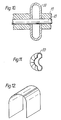
- Figs. 12-15 show some different embodiments of the insulation element according to the invention.
- the embodiments in Figs. 12 and 13 will be particularly advantageous in erecting flexible insulation membranes, for instance for large tanks for cryogenic materials, while one can envisage other appliances of the insulation element where embodiments as in Figs. 14 and 15 will be more suitable.
Landscapes
- Engineering & Computer Science (AREA)
- General Engineering & Computer Science (AREA)
- Mechanical Engineering (AREA)
- Filling Or Discharging Of Gas Storage Vessels (AREA)
- Ceramic Capacitors (AREA)
- Thermistors And Varistors (AREA)
- Networks Using Active Elements (AREA)
- Electronic Switches (AREA)
- Photoreceptors In Electrophotography (AREA)
- Apparatuses And Processes For Manufacturing Resistors (AREA)
- Fixed Capacitors And Capacitor Manufacturing Machines (AREA)
- Formation Of Insulating Films (AREA)
- Control Of Vending Devices And Auxiliary Devices For Vending Devices (AREA)
- Inorganic Insulating Materials (AREA)
- Laminated Bodies (AREA)
- Thermal Insulation (AREA)
Claims (10)
Priority Applications (1)
| Application Number | Priority Date | Filing Date | Title |
|---|---|---|---|
| AT82901026T ATE15936T1 (de) | 1981-04-28 | 1982-04-13 | Isolierelement, sowie verfahren zu dessen herstellung und verwendung. |
Applications Claiming Priority (2)
| Application Number | Priority Date | Filing Date | Title |
|---|---|---|---|
| NO811451A NO148721C (no) | 1981-04-28 | 1981-04-28 | Isolasjonselement samt fremgangsmaate for fremstilling og anvendelse av dette |
| NO811451 | 1981-04-28 |
Publications (2)
| Publication Number | Publication Date |
|---|---|
| EP0077335A1 EP0077335A1 (de) | 1983-04-27 |
| EP0077335B1 true EP0077335B1 (de) | 1985-10-02 |
Family
ID=19886046
Family Applications (1)
| Application Number | Title | Priority Date | Filing Date |
|---|---|---|---|
| EP82901026A Expired EP0077335B1 (de) | 1981-04-28 | 1982-04-13 | Isolierelement, sowie verfahren zu dessen herstellung und verwendung |
Country Status (9)
| Country | Link |
|---|---|
| EP (1) | EP0077335B1 (de) |
| JP (1) | JPS57186699A (de) |
| AT (1) | ATE15936T1 (de) |
| AU (1) | AU8330582A (de) |
| DE (1) | DE3266630D1 (de) |
| DK (1) | DK574382A (de) |
| FI (1) | FI824438L (de) |
| NO (1) | NO148721C (de) |
| WO (1) | WO1982003904A1 (de) |
Families Citing this family (5)
| Publication number | Priority date | Publication date | Assignee | Title |
|---|---|---|---|---|
| FR2854940B1 (fr) * | 2003-05-16 | 2005-07-15 | A T I | Isolant multicouche |
| DE102004043201A1 (de) * | 2004-09-03 | 2006-03-09 | Heinz Woitzel | Verfahren und Einrichtung zur Herstellung von Sandwichelementen |
| JP2014210379A (ja) * | 2013-04-18 | 2014-11-13 | 太陽工業株式会社 | 積層シート、及び、積層シートの接合方法 |
| CN105822899A (zh) * | 2016-05-11 | 2016-08-03 | 悌埃保温制品(上海)有限公司 | 具有弯曲特性的用于液化气低温储罐的保温板 |
| CN105805540A (zh) * | 2016-05-11 | 2016-07-27 | 悌埃保温制品(上海)有限公司 | 具有弯曲特性的用于液化气低温储罐的倒u型保温板 |
Family Cites Families (4)
| Publication number | Priority date | Publication date | Assignee | Title |
|---|---|---|---|---|
| US1748575A (en) * | 1928-10-19 | 1930-02-25 | Ind Welded Alloys Inc | Lined tank or pressure vessel |
| CH448651A (de) * | 1965-12-24 | 1967-12-15 | J Kauffmann Eduard | Verschalungselement |
| JPS5021004B1 (de) * | 1970-03-13 | 1975-07-19 | ||
| FR2304509A1 (fr) * | 1975-03-21 | 1976-10-15 | Pittsburgh Des Moines Steel | Dispositif de support et de fixation de reservoirs pour des liquides a basse temperature, notamment pour le transport maritime |
-
1981
- 1981-04-28 NO NO811451A patent/NO148721C/no unknown
-
1982
- 1982-04-13 DE DE8282901026T patent/DE3266630D1/de not_active Expired
- 1982-04-13 AU AU83305/82A patent/AU8330582A/en not_active Abandoned
- 1982-04-13 FI FI824438A patent/FI824438L/fi not_active Application Discontinuation
- 1982-04-13 WO PCT/NO1982/000020 patent/WO1982003904A1/en not_active Ceased
- 1982-04-13 AT AT82901026T patent/ATE15936T1/de not_active IP Right Cessation
- 1982-04-13 EP EP82901026A patent/EP0077335B1/de not_active Expired
- 1982-04-23 JP JP57068560A patent/JPS57186699A/ja active Pending
- 1982-12-27 DK DK574382A patent/DK574382A/da not_active Application Discontinuation
Also Published As
| Publication number | Publication date |
|---|---|
| FI824438A0 (fi) | 1982-12-23 |
| WO1982003904A1 (en) | 1982-11-11 |
| FI824438A7 (fi) | 1982-10-29 |
| NO811451L (no) | 1982-10-29 |
| FI824438L (fi) | 1982-12-23 |
| ATE15936T1 (de) | 1985-10-15 |
| NO148721C (no) | 1983-11-30 |
| AU8330582A (en) | 1982-11-24 |
| DE3266630D1 (en) | 1985-11-07 |
| EP0077335A1 (de) | 1983-04-27 |
| NO148721B (no) | 1983-08-22 |
| DK574382A (da) | 1982-12-27 |
| JPS57186699A (en) | 1982-11-17 |
Similar Documents
| Publication | Publication Date | Title |
|---|---|---|
| FI113083B (fi) | Vedenpitävä ja lämpöeristetty säiliö, jossa on parannetut pitkittäiset leikkauksen avaruuskulmat | |
| KR102090266B1 (ko) | 극저온 단열 구조 및 이의 시공 방법 | |
| US4366917A (en) | Cryogenic tank | |
| US4442585A (en) | Method of construction for thermal and acoustic insulation blankets | |
| CN110088522B (zh) | 密封且热绝缘的罐的角部结构及其组装方法 | |
| JP7382975B2 (ja) | 液体ドームの組み立て方法 | |
| CN104870882B (zh) | 密封绝热罐 | |
| JP6480073B1 (ja) | 密閉断熱タンク用の固定装置の取付方法 | |
| JP2016513226A (ja) | 貫通要素を備えたタンク壁 | |
| KR101375262B1 (ko) | 액화천연가스 저장탱크의 1차 방벽의 보강 부재용 고정 구조체 | |
| AU2021335915A1 (en) | Tank feasible for cryogenic service | |
| US5657594A (en) | Heat insulation covering structure of a low temperature cargo tank | |
| EP0077335B1 (de) | Isolierelement, sowie verfahren zu dessen herstellung und verwendung | |
| EP3798495B1 (de) | Isoliervorrichtung für tieftemperaturrohr | |
| TW202408878A (zh) | 包括貫通導管的槽壁 | |
| KR102614343B1 (ko) | 복수의 영역을 갖는 밀폐 및 단열 탱크 | |
| US7854241B2 (en) | Metal-clad insulating complex for a pipe | |
| AU2014252951A1 (en) | Insulating block for producing a sealed and insulated tank wall | |
| KR102883950B1 (ko) | 액화가스 저장탱크의 단열층 및 멤브레인 고정장치 | |
| AU2008233375A1 (en) | Pipe Insulation | |
| JP2016524679A (ja) | 流体貯蔵容器の断熱のための自立型ケースを製造する方法及び該方法によって製造された自立型ケース | |
| JP2024082266A (ja) | 密閉断熱タンク | |
| KR101225168B1 (ko) | 액화천연가스 화물창의 단열구조 및 이를 구비한 선박 | |
| US4004394A (en) | Method for insulation of curved surfaces | |
| KR20230081968A (ko) | 하중 지지 구조체에 내장된 밀폐 단열 탱크의 조립 방법 |
Legal Events
| Date | Code | Title | Description |
|---|---|---|---|
| PUAI | Public reference made under article 153(3) epc to a published international application that has entered the european phase |
Free format text: ORIGINAL CODE: 0009012 |
|
| AK | Designated contracting states |
Designated state(s): AT BE CH DE FR GB LI LU NL SE |
|
| 17P | Request for examination filed |
Effective date: 19830429 |
|
| GRAA | (expected) grant |
Free format text: ORIGINAL CODE: 0009210 |
|
| AK | Designated contracting states |
Designated state(s): AT BE CH DE FR GB LI LU NL SE |
|
| PG25 | Lapsed in a contracting state [announced via postgrant information from national office to epo] |
Ref country code: LI Effective date: 19851002 Ref country code: CH Effective date: 19851002 Ref country code: AT Effective date: 19851002 |
|
| REF | Corresponds to: |
Ref document number: 15936 Country of ref document: AT Date of ref document: 19851015 Kind code of ref document: T |
|
| PG25 | Lapsed in a contracting state [announced via postgrant information from national office to epo] |
Ref country code: SE Effective date: 19851030 |
|
| REF | Corresponds to: |
Ref document number: 3266630 Country of ref document: DE Date of ref document: 19851107 |
|
| ET | Fr: translation filed | ||
| REG | Reference to a national code |
Ref country code: CH Ref legal event code: PL |
|
| PG25 | Lapsed in a contracting state [announced via postgrant information from national office to epo] |
Ref country code: LU Free format text: LAPSE BECAUSE OF NON-PAYMENT OF DUE FEES Effective date: 19860430 |
|
| PLBE | No opposition filed within time limit |
Free format text: ORIGINAL CODE: 0009261 |
|
| STAA | Information on the status of an ep patent application or granted ep patent |
Free format text: STATUS: NO OPPOSITION FILED WITHIN TIME LIMIT |
|
| 26N | No opposition filed | ||
| GBPC | Gb: european patent ceased through non-payment of renewal fee | ||
| PGFP | Annual fee paid to national office [announced via postgrant information from national office to epo] |
Ref country code: NL Payment date: 19870430 Year of fee payment: 6 |
|
| PG25 | Lapsed in a contracting state [announced via postgrant information from national office to epo] |
Ref country code: GB Effective date: 19881121 |
|
| PG25 | Lapsed in a contracting state [announced via postgrant information from national office to epo] |
Ref country code: BE Effective date: 19890430 |
|
| BERE | Be: lapsed |
Owner name: A/S TEKNISK ISOLERING Effective date: 19890430 |
|
| PG25 | Lapsed in a contracting state [announced via postgrant information from national office to epo] |
Ref country code: NL Effective date: 19891101 |
|
| NLV4 | Nl: lapsed or anulled due to non-payment of the annual fee | ||
| PG25 | Lapsed in a contracting state [announced via postgrant information from national office to epo] |
Ref country code: FR Free format text: LAPSE BECAUSE OF NON-PAYMENT OF DUE FEES Effective date: 19891228 |
|
| PG25 | Lapsed in a contracting state [announced via postgrant information from national office to epo] |
Ref country code: DE Effective date: 19900103 |
|
| REG | Reference to a national code |
Ref country code: FR Ref legal event code: ST |