EP0077402A1 - Fluorescent discharge lamp - Google Patents
Fluorescent discharge lamp Download PDFInfo
- Publication number
- EP0077402A1 EP0077402A1 EP82901159A EP82901159A EP0077402A1 EP 0077402 A1 EP0077402 A1 EP 0077402A1 EP 82901159 A EP82901159 A EP 82901159A EP 82901159 A EP82901159 A EP 82901159A EP 0077402 A1 EP0077402 A1 EP 0077402A1
- Authority
- EP
- European Patent Office
- Prior art keywords
- phosphor
- layer
- trivalent
- fluorescent
- discharge lamp
- Prior art date
- Legal status (The legal status is an assumption and is not a legal conclusion. Google has not performed a legal analysis and makes no representation as to the accuracy of the status listed.)
- Granted
Links
Images

Classifications
-
- H—ELECTRICITY
- H01—ELECTRIC ELEMENTS
- H01J—ELECTRIC DISCHARGE TUBES OR DISCHARGE LAMPS
- H01J61/00—Gas-discharge or vapour-discharge lamps
- H01J61/02—Details
- H01J61/12—Selection of substances for gas fillings; Specified operating pressure or temperature
-
- H—ELECTRICITY
- H01—ELECTRIC ELEMENTS
- H01J—ELECTRIC DISCHARGE TUBES OR DISCHARGE LAMPS
- H01J61/00—Gas-discharge or vapour-discharge lamps
- H01J61/02—Details
- H01J61/38—Devices for influencing the colour or wavelength of the light
- H01J61/42—Devices for influencing the colour or wavelength of the light by transforming the wavelength of the light by luminescence
- H01J61/48—Separate coatings of different luminous materials
Definitions
- This invention relates to a fluorescent discharge lamp having a plurality of phosphor layers.
- the phosphor layer is provided on the inner surface of a galss tube for low pressure type fluorescent discharge lamps and on the inner surface of an outer glass tube having a light'emitting tube accommodated therein for the high pressure type.
- fluorescent lamps which are representative of low pressure type fluorescent discharge lamps a greater part of ultraviolet rays generated by means of an electric discharge of a mercury vapor is absorbed by the phosphor layer to be converted to light of a long wavelength and one part thereof passes through the phosphor layer to be absorbed by glass resulting in a loss (an absorption loss), while also one part thereof is reflected from the phosphor layer and absorbed by the electric discharge resulting in a loss (a reflection loss).
- the high pressure type fluorescent discharge lamps such as high pressure mercury fluorescent lamps there exist members for abosrbing ultraviolet rays such as glass and the light emitting tube other than the fluorescent layer to cause an absorbtion and a reflection loss such as described above.
- a phosphor powder normally synthesized has a small proportion of particles having the large and small mean particle diameters required for said constitution, and when it is separated by means such as elutriation or the like, there is provided what has undersirable intermediate mean particle diameters in a large amount.
- Nonuse of those undesirable ones is not considered in mass production systems and therefore when it is attempted to pulverize them by a grinder such as a ball mill and use them as what has a small mean particle diameter, the destruction of the phosphor moves on by means of the so-called pressure disruption in the pulverizing step to decrease a quantum yeild (a ratio of the number of emitting quanta to that of absorbed quanta, that is, a quantum yield upon a conversion of a wavelength). Thereby a loss in energy increases. Thus it has been found that, even if the phosphor layers were stacked into the abovementioned construction, the desired lamp efficiency is not obtained.
- Phosphors used with electric discharge lamps are, in many causes, composed of the matrix and the activator.
- the yttrium silicate (Y 2 SiO 5 ) is a matrix and the terbium (Tb) is an activator.
- the Table takes that trivalent activated yttrium silicate posphor as an example and indicates changes in reflection factor to a ultraviolet ray and quantum yield (relative value) when a concentration of the activator, terbium (Tb) is changed in concentration.
- This phosphor provides the highest luminesence output with ultraviolet excitation when it includes 0.16 gram atom of termium (Tb) with respect to substantially 0.84 gram atom of yttrium.
- this concentration of the activator is normally adopted.
- Nos. 1 to 5 have the mean particle diameter (10 microns) in the order of a normally used extent and are merely changed in concentration of the activator, terbium (Tb). No.
- the reflection factor to the ultraviolet ray designates its value when MgO in made 1.00.
- the present invention is arranged to dispose a phosphor excited with a ultraviolet ray to emit light in plurality of layers on a glass substrate so that the phosphor layers high in reflection factor to the ultraviolet ray are located on the side of the glass substrate and the phosphor layers low in reflection factor to the ultraviolet ray are located on the side of an electric discharge while a concentration of an activator for the phosphor is successively high starting with that phosphor layer located near to the glass substitute thereby to improve a light output.
- Figure 1 is a longitudinal sectional view of a fluorescent lamp illustrating the mode of one embodiment of the present invention
- Figure 2 is an enlarged view of the A part in Figure 1.
- FIG. 1 is a schematic longitudinal sectional view of the fluorescent lamp of the present invention wherein (1) is a glass tube and (2) is an electrode sealed through either end thereof, a space within the glass tube being charged with mercury and not less than one of rare gases. Stacked on the inner surface of the glass tube (1) are two phosphor layers (3) and (4) composed of a phosphor having different concentration of an activatior respectively so that one (3) of the phosphor layers is formed to occupy a position near to the inner surface of the glass tube and also the other phosphor layer (4) is formed to occupy a position on the side of an electric discharge.
- the phosphor of the one phosphor layer (3) has a low concentration of the activator as compared with that of the other phosphor layer (4) and therefore has a reflection factor to a ultraviolet ray higher than that of the other phosphor layer (4).
- an electric discharge occurs in the space within the galss tube to generate an ultraviolet ray principally at a wavelength of 254nm. This stimulates the phsphor layers (3) and (4) to produce a light ray having a longer wavelength.
- the optical operation of what has the phosphor layers (3) and (4) thus formed will be outlined.
- a greater part of the ultraviolet ray is first absorbed by the phosphor layer (4) located at its position remote from the glass tube (1) and low in reflection factor to the ultraviolet ray and be converted to light of a long wavelength.
- one part is not absorbed by that phosphor layer (4) and some part of the ultraviolet ray passed through this layer (4) to reach the phosphor layer (3) high in reflection factor to the ultraviolet ray and at the position near to the glass tube (1) is converted to light of a long wavelength by the phosphor having a high quantum efficiency with a high conversion efficiency.
- some part is again reflected to be returned back to the phosphor layer (4) where it is converted to light of a long wavelength.
- the phosphor layer (4) low in reflection factor to the ultraviolet ray on the discharge side and the phosphor layer (3) high in reflection factor to the ultraviolet ray and enhanced in quantum efficiency on the side of the glass substrate an absorption loss and a reflection loss are decreased and also a loss in energy upon the conversion of the wavelength of light by the phosphor is decreased.
- To form the phosphor layers (3) and (4) by stacking in the present invention can be carried out by a conventional process such as comprising mixing each phosphor with butyl acetate or another solvent along with a binder such as nitrocellulose, coating the inner surface with a suspension and removing the binder by dry heating.
- the heating step of removing the binder may be interposed between the steps of forming the layer (3) and the layer (4) (the formation of the layer (3) ⁇ the heating ⁇ the formation of the layer (4) ⁇ the heating).
- it may be executed only once after the stacking of the layer (4) on the layer (3) (The formation of the layer (3) ⁇ the formation of the layer (4) + the heating).
- Still more not less than three phosphor layers may be stacked.
- the concentration of the activator is successively increased starting with the layer located at the position near to the glass substrate.
- an yttrium silicate phosphor (Y0.96Tb0.04) 2 SiO 5 of the mean particle diameter of 10 ⁇ having a low concentration of an activator was used to form the phosphor layer (3) on the inner surface of a glass tube with an attached amount of 2.8mg/cm 2 and then an yttrium silicate phosphor (Y0.84Tb0.16) 2 Si0 5 of the mean particle diameter of 10 ⁇ having a high concentration of the activator was used to form the phosphor layer (4) thereon with an attached amount of 2.4 g/cm 2 to produce a fluorescent lamp having a maximum luminescence at 543nm and emitting green light.
- a light output had a luminous flux of 5200 lumens.
- the yttrium silicate phosphor (0.84Tb0.16) 2 Si0 5 of the mean particle diameter of 10 ⁇ having said high concentration of the activator was used to form a phosphor layer consisting of a single layer with an attached amount of 5.2mg/cm 2 into a 40 watt fluorescent lamp having a luminous flux of 4990 lumens that was as low as about 4%.
- a phosphor layer was formed on the inner surface of a glass tube of an yttrium silicate phosphor (Y0.84 TbO.16) having a high concentration of the activator by reducing the mean particle diameter to 2.7 microns through the pulverization with an attached amount of 1.7mg/cm , and then a phosphor layer was formed thereon of an yttrium silicate phosphor (Y0.84Tb0.16) 2 SiO 3 of the mean particle diameter of 10 ⁇ having a high concentration of the activator with an attached amount of 2.4mg/cm 2 .
- the resulting 40 watt fluorescent lamp had a luminous flux of 4950 lumens that was as low as about 5%.
- the mixture (1) was used to first form the phosphor layer (3) on the inner surface of a glass tube with an attached amount of 2.5mg/cm 2 and the mixture (2) was used to form the phosphor layer (4) thereon with an attached amount of 2.5mg/cm to produce a 40 watt fluorescent lamp.
- a luminous flux of the lamp is of 3800 lumens and an improvement of 4% has been recognized as compared with 3650 lumens of a lamp consisting of a single layer having an attached amount of 4.8 mg/cm 2 by using only the mixture (2) and produced for comparison purpose. Also 4% improved as compared with 3610 lumens of a lamp having formed thereon a phosphor layer with an attached amount of 5mg/cm 2 by using a mixture of the mean particle diameter of 2.0 microns provided through the pulverization of the mixture (2) and stacked thereon a phosphor layer with an attached amount of 2.3mg/cm 2 by using the mixture (2) without the pulverization.
- the mixture (1) described in Example 2 was pulverized to make the mean particle diameter 2.0 microns and used to form the phosphor layer (3) with an attached amount of 1.2mg/cm on the inner surface of a glass tube and the mixture (2) with the mean particle diameter of 7 microns described in Example 2 was used without the pulverization to form the phosphor layer (4) with an attached amount of 2.5mg/cm 2 thereon to produce a 40 watt fluorescent lamp.
- a luminous flux of the lamp is of 3720 lumens and about 2 to 3% improved as compared with the comparison lamp described in
- the effect of the present invention is obtained even in the presence of a difference in mean particle diameter between the phosphor layers (3) and (4). That is to say, while the effect of improvement of a light output decreases by, a decrease in quantum efficiency due to the pulverization, there exists still an extent of improvement of the quantum efficiency due to an decrease in concentration of the activator so that the effect of improvement of the light output is yet maintained. And in this case against some sacrifice of the effect of improvement of the light output a weight of the attached phosphor is reduced originating from the decrease in mean particle diameter resulting in the provision of the effect of saving of the phosphors.
- the present invention is applicable to electric discharge lamps using phsophors varied in reflection factor to an ultraviolet ray (excited light) with concentrations of activators other than those described above and also applicable to the use of a phosphor including two types of the activator.
- a green luminescent phosphor having trivalent cerium (Ce) and trivalent terbium (Tb) as activators and lanthanum phosphate, magnesium borate, yttrium silicate or the like as a matrix
- Cerium absorb an ultraviolet ray and transmits its energy to terbium to enhance the green luminescence of terbium
- the cerium may be also called a sensitizer.
- the reflection factor to the ultraviolet ray may be changed by adjusting the concentration of the cerium.
- the concentrations of the cerium and terbium may be adjusted.
- a ratio of the concentration of the cerium to that of the terbium is not suitable then the transmission of energy from the cerium to the terbium is not perfect and the luminescence resulting from the cerium to lie in a range of ultraviolet through blue wavelengths becomes enhanced to decrease the quantum efficiency concerning the desired green luminescence resulting from the terbium.
- the essential part of the present invention as left intact may be carried out with other types of electric discharge lamps such as high pressure type fluorescent discharge lamp,.for example, fluorescent high pressure mercury lamps or fluorescent lamps comprising the member for controlling an electric discharge path therein.
- high pressure type fluorescent discharge lamp for example, fluorescent high pressure mercury lamps or fluorescent lamps comprising the member for controlling an electric discharge path therein.
Landscapes
- Vessels And Coating Films For Discharge Lamps (AREA)
Abstract
Description
- This invention relates to a fluorescent discharge lamp having a plurality of phosphor layers.
- As well known, the phosphor layer is provided on the inner surface of a galss tube for low pressure type fluorescent discharge lamps and on the inner surface of an outer glass tube having a light'emitting tube accommodated therein for the high pressure type.
- In fluorescent lamps which are representative of low pressure type fluorescent discharge lamps a greater part of ultraviolet rays generated by means of an electric discharge of a mercury vapor is absorbed by the phosphor layer to be converted to light of a long wavelength and one part thereof passes through the phosphor layer to be absorbed by glass resulting in a loss (an absorption loss), while also one part thereof is reflected from the phosphor layer and absorbed by the electric discharge resulting in a loss (a reflection loss). Also in the high pressure type fluorescent discharge lamps such as high pressure mercury fluorescent lamps there exist members for abosrbing ultraviolet rays such as glass and the light emitting tube other than the fluorescent layer to cause an absorbtion and a reflection loss such as described above.
- In order to improve the light output from such fluorescent discharge lamps, it is desirable to decrease the absorption and reflection losses and absorb ultraviolet rays generated with electric discharges by the phosphor layer as much as possible. As a method of decreasing the absorption and reflection losses, it has been already known to stack a plurality of phosphor layers on a glass substrate and compose the layer located nearer to the electric discharge side of phosphor particles low in reflection factor to ultraviolet rays. According to Japanese patent publication No. 32,956/1975 there is disclosed the fact that, upon stacking a plurality of phosphor layers different in reflection factor to ultraviolet rays from one another, phosphor low in reflection factor to ultraviolet rays uses those large in mean particle diameter while phosphors high in reflection factor to ultraviolet rays use those small in means particle diameter.
- In order to constitute the phosphor layers in this way, it is necessary to separately provide a phosphor having a small mean particle diameter and that having a large mean particle diameter in substantially equal amounts and also it is required that there is a large difference in mean particle diameter between the two. According to follow-up experiments of the inventors, however, a phosphor powder normally synthesized has a small proportion of particles having the large and small mean particle diameters required for said constitution, and when it is separated by means such as elutriation or the like, there is provided what has undersirable intermediate mean particle diameters in a large amount. Nonuse of those undesirable ones is not considered in mass production systems and therefore when it is attempted to pulverize them by a grinder such as a ball mill and use them as what has a small mean particle diameter, the destruction of the phosphor moves on by means of the so-called pressure disruption in the pulverizing step to decrease a quantum yeild (a ratio of the number of emitting quanta to that of absorbed quanta, that is, a quantum yield upon a conversion of a wavelength). Thereby a loss in energy increases. Thus it has been found that, even if the phosphor layers were stacked into the abovementioned construction, the desired lamp efficiency is not obtained.
- Thus so far as the present inventors have examined into the provision of phosphors high in reflection factor to ultraviolet rays and also high in quantum yield, it has been brought to light that if a concentration of an activator is changed to adjust a reflection factor to ultraviolet rays then a quantum yield can be improved.
- This phenomenon will be described as follows: Phosphors used with electric discharge lamps are, in many causes, composed of the matrix and the activator. For example, in trivalent terbium activated yttrium silicate [(Y · Tb)2SiO5] described in Japanes patent publication No. 37,670/1973, the yttrium silicate (Y2SiO5) is a matrix and the terbium (Tb) is an activator.
- The Table takes that trivalent activated yttrium silicate posphor as an example and indicates changes in reflection factor to a ultraviolet ray and quantum yield (relative value) when a concentration of the activator, terbium (Tb) is changed in concentration. This phosphor provides the highest luminesence output with ultraviolet excitation when it includes 0.16 gram atom of termium (Tb) with respect to substantially 0.84 gram atom of yttrium. Thus for use with electric discharge lamps, this concentration of the activator is normally adopted. In the Table, Nos. 1 to 5 have the mean particle diameter (10 microns) in the order of a normally used extent and are merely changed in concentration of the activator, terbium (Tb). No. 6 has the same concentration of the activator as No. 5 but has the mean particle diameter decreased to 2.7 microns by means of a grinder such as a ball mill or the like. As shown in the Table, a reduction in concentration of the activator causes an increase in reflection factor to a ultraviolet ray (a decrease in amount of sbsorption of the ultraviolet ray) and improvent in quantum yield. Furthermore, by comparing No. 1 and No. 6 having the same reflection factors to the ultraviolet ray with each other, it is found that a far more advantageous quantum yield is obtained when the reflection factor to the ultraviolet ray is adjusted by changing the concentration of the activator than when it is done by changing the mean particle diameter through the pulverization.
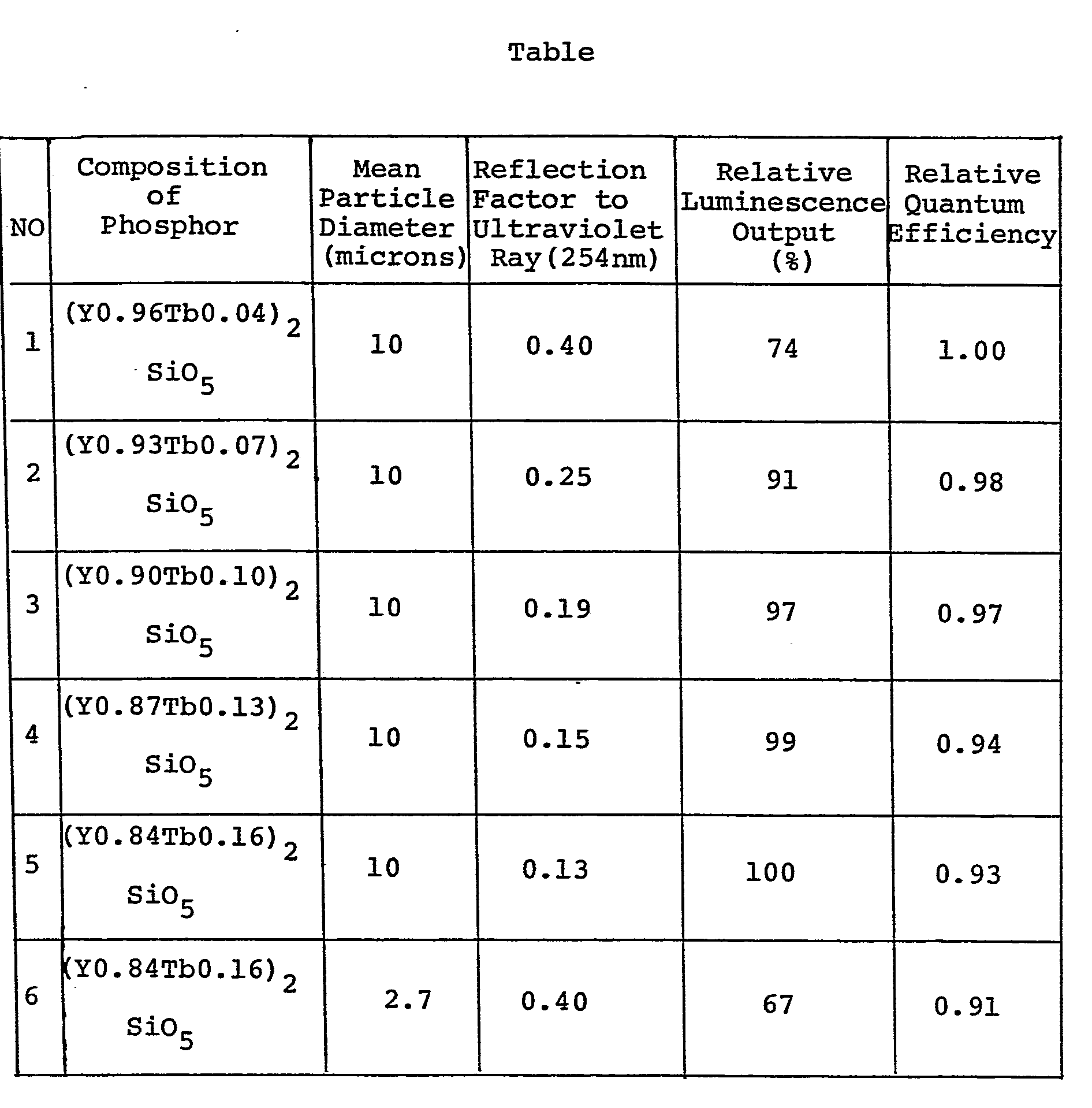
- In this Table the reflection factor to the ultraviolet ray designates its value when MgO in made 1.00.
- The present invention is arranged to dispose a phosphor excited with a ultraviolet ray to emit light in plurality of layers on a glass substrate so that the phosphor layers high in reflection factor to the ultraviolet ray are located on the side of the glass substrate and the phosphor layers low in reflection factor to the ultraviolet ray are located on the side of an electric discharge while a concentration of an activator for the phosphor is successively high starting with that phosphor layer located near to the glass substitute thereby to improve a light output.
- Figure 1 is a longitudinal sectional view of a fluorescent lamp illustrating the mode of one embodiment of the present invention; and Figure 2 is an enlarged view of the A part in Figure 1.
- An embodiment of the present invention will be described by taking a fluorescent lamp as an example. Figure 1 is a schematic longitudinal sectional view of the fluorescent lamp of the present invention wherein (1) is a glass tube and (2) is an electrode sealed through either end thereof, a space within the glass tube being charged with mercury and not less than one of rare gases. Stacked on the inner surface of the glass tube (1) are two phosphor layers (3) and (4) composed of a phosphor having different concentration of an activatior respectively so that one (3) of the phosphor layers is formed to occupy a position near to the inner surface of the glass tube and also the other phosphor layer (4) is formed to occupy a position on the side of an electric discharge. Here the phosphor of the one phosphor layer (3) has a low concentration of the activator as compared with that of the other phosphor layer (4) and therefore has a reflection factor to a ultraviolet ray higher than that of the other phosphor layer (4). Upon the application of a voltage across the electrodes, an electric discharge occurs in the space within the galss tube to generate an ultraviolet ray principally at a wavelength of 254nm. This stimulates the phsphor layers (3) and (4) to produce a light ray having a longer wavelength.
- The optical operation of what has the phosphor layers (3) and (4) thus formed will be outlined. A greater part of the ultraviolet ray is first absorbed by the phosphor layer (4) located at its position remote from the glass tube (1) and low in reflection factor to the ultraviolet ray and be converted to light of a long wavelength. And one part is not absorbed by that phosphor layer (4) and some part of the ultraviolet ray passed through this layer (4) to reach the phosphor layer (3) high in reflection factor to the ultraviolet ray and at the position near to the glass tube (1) is converted to light of a long wavelength by the phosphor having a high quantum efficiency with a high conversion efficiency. Also some part is again reflected to be returned back to the phosphor layer (4) where it is converted to light of a long wavelength. By disposing the phosphor layer (4) low in reflection factor to the ultraviolet ray on the discharge side and the phosphor layer (3) high in reflection factor to the ultraviolet ray and enhanced in quantum efficiency on the side of the glass substrate, an absorption loss and a reflection loss are decreased and also a loss in energy upon the conversion of the wavelength of light by the phosphor is decreased.
- To form the phosphor layers (3) and (4) by stacking in the present invention can be carried out by a conventional process such as comprising mixing each phosphor with butyl acetate or another solvent along with a binder such as nitrocellulose, coating the inner surface with a suspension and removing the binder by dry heating. Also the heating step of removing the binder may be interposed between the steps of forming the layer (3) and the layer (4) (the formation of the layer (3) → the heating → the formation of the layer (4) → the heating). Alternatively, it may be executed only once after the stacking of the layer (4) on the layer (3) (The formation of the layer (3) → the formation of the layer (4) + the heating).
- Still more not less than three phosphor layers may be stacked. In this case the concentration of the activator is successively increased starting with the layer located at the position near to the glass substrate.
- Concrete Examples of the present invention will be described hereinafter.
- Upon manufacturing a 40 wat fluorescent lamp, an yttrium silicate phosphor (Y0.96Tb0.04)2SiO5 of the mean particle diameter of 10µ having a low concentration of an activator was used to form the phosphor layer (3) on the inner surface of a glass tube with an attached amount of 2.8mg/cm2 and then an yttrium silicate phosphor (Y0.84Tb0.16)2Si05 of the mean particle diameter of 10µ having a high concentration of the activator was used to form the phosphor layer (4) thereon with an attached amount of 2.4 g/cm2 to produce a fluorescent lamp having a maximum luminescence at 543nm and emitting green light. A light output had a luminous flux of 5200 lumens. For comparison purposes the yttrium silicate phosphor (0.84Tb0.16)2Si05 of the mean particle diameter of 10µ having said high concentration of the activator was used to form a phosphor layer consisting of a single layer with an attached amount of 5.2mg/cm2 into a 40 watt fluorescent lamp having a luminous flux of 4990 lumens that was as low as about 4%. Also a phosphor layer was formed on the inner surface of a glass tube of an yttrium silicate phosphor (Y0.84 TbO.16) having a high concentration of the activator by reducing the mean particle diameter to 2.7 microns through the pulverization with an attached amount of 1.7mg/cm , and then a phosphor layer was formed thereon of an yttrium silicate phosphor (Y0.84Tb0.16)2SiO3 of the mean particle diameter of 10µ having a high concentration of the activator with an attached amount of 2.4mg/cm2. The resulting 40 watt fluorescent lamp had a luminous flux of 4950 lumens that was as low as about 5%.
- In order to provide a fluorescent lamp obtaing simultaneously a high efficiency and a high color reudering property by concentrating luminescence in a range of wavelengths of blue, green and red such as disclosed, for example, in Japanese patent publication No. 22,117/1973, the undermentioned phosphor mixtures (1) and (2) were prepared.
- (1) A mixture of phosphors having low concentrations of activators

- (2) A mixture of phosphors having high cencentration of activators.

- Mixing ratios of the two mixtures are adjusted respectively so that luminescent colors are substantially equal to one another and also that while light at a color temperature of 4200 K is obtained. Also the two mixtures have the mean particle diameter of about 7 microns. The mixture (1) was used to first form the phosphor layer (3) on the inner surface of a glass tube with an attached amount of 2.5mg/cm2 and the mixture (2) was used to form the phosphor layer (4) thereon with an attached amount of 2.5mg/cm to produce a 40 watt fluorescent lamp. A luminous flux of the lamp is of 3800 lumens and an improvement of 4% has been recognized as compared with 3650 lumens of a lamp consisting of a single layer having an attached amount of 4.8 mg/cm2 by using only the mixture (2) and produced for comparison purpose. Also 4% improved as compared with 3610 lumens of a lamp having formed thereon a phosphor layer with an attached amount of 5mg/cm2 by using a mixture of the mean particle diameter of 2.0 microns provided through the pulverization of the mixture (2) and stacked thereon a phosphor layer with an attached amount of 2.3mg/cm2 by using the mixture (2) without the pulverization.
- The mixture (1) described in Example 2 was pulverized to make the mean particle diameter 2.0 microns and used to form the phosphor layer (3) with an attached amount of 1.2mg/cm on the inner surface of a glass tube and the mixture (2) with the mean particle diameter of 7 microns described in Example 2 was used without the pulverization to form the phosphor layer (4) with an attached amount of 2.5mg/cm2 thereon to produce a 40 watt fluorescent lamp. A luminous flux of the lamp is of 3720 lumens and about 2 to 3% improved as compared with the comparison lamp described in
- As described in Example 3, the effect of the present invention is obtained even in the presence of a difference in mean particle diameter between the phosphor layers (3) and (4). That is to say, while the effect of improvement of a light output decreases by, a decrease in quantum efficiency due to the pulverization, there exists still an extent of improvement of the quantum efficiency due to an decrease in concentration of the activator so that the effect of improvement of the light output is yet maintained. And in this case against some sacrifice of the effect of improvement of the light output a weight of the attached phosphor is reduced originating from the decrease in mean particle diameter resulting in the provision of the effect of saving of the phosphors.
- The present invention is applicable to electric discharge lamps using phsophors varied in reflection factor to an ultraviolet ray (excited light) with concentrations of activators other than those described above and also applicable to the use of a phosphor including two types of the activator. For example in a green luminescent phosphor having trivalent cerium (Ce) and trivalent terbium (Tb) as activators and lanthanum phosphate, magnesium borate, yttrium silicate or the like as a matrix, cerium absorb an ultraviolet ray and transmits its energy to terbium to enhance the green luminescence of terbium (In this case, the cerium may be also called a sensitizer.) In such a case, however, the reflection factor to the ultraviolet ray may be changed by adjusting the concentration of the cerium. Also the concentrations of the cerium and terbium may be adjusted. In case dependent on the latter method if a ratio of the concentration of the cerium to that of the terbium is not suitable then the transmission of energy from the cerium to the terbium is not perfect and the luminescence resulting from the cerium to lie in a range of ultraviolet through blue wavelengths becomes enhanced to decrease the quantum efficiency concerning the desired green luminescence resulting from the terbium. Thus it is desirable to adjust the concentration ratio of the cerium to the terbium while being held properly so as not to cause such a phenomenon.
- From the foregoing description it is apparent that, with the use of mixed phosphors such as described in Example 2 upon carrying out the present inventon, the effect is obtained even with the adjustment of the activator's concentration(s) for a specified phosphor(s) alone among a plurality of phosphors.
- From the foregoing description it is understood that, the essential part of the present invention as left intact may be carried out with other types of electric discharge lamps such as high pressure type fluorescent discharge lamp,.for example, fluorescent high pressure mercury lamps or fluorescent lamps comprising the member for controlling an electric discharge path therein.
Claims (6)
Applications Claiming Priority (2)
| Application Number | Priority Date | Filing Date | Title |
|---|---|---|---|
| JP56060798A JPS57174847A (en) | 1981-04-22 | 1981-04-22 | Fluorescent discharge lamp |
| JP60798/81 | 1981-04-22 |
Publications (3)
| Publication Number | Publication Date |
|---|---|
| EP0077402A1 true EP0077402A1 (en) | 1983-04-27 |
| EP0077402A4 EP0077402A4 (en) | 1983-08-03 |
| EP0077402B1 EP0077402B1 (en) | 1986-02-12 |
Family
ID=13152688
Family Applications (1)
| Application Number | Title | Priority Date | Filing Date |
|---|---|---|---|
| EP82901159A Expired EP0077402B1 (en) | 1981-04-22 | 1982-04-21 | Fluorescent discharge lamp |
Country Status (6)
| Country | Link |
|---|---|
| US (1) | US4559470A (en) |
| EP (1) | EP0077402B1 (en) |
| JP (1) | JPS57174847A (en) |
| KR (1) | KR860000939B1 (en) |
| DE (1) | DE3269045D1 (en) |
| WO (1) | WO1982003726A1 (en) |
Cited By (1)
| Publication number | Priority date | Publication date | Assignee | Title |
|---|---|---|---|---|
| EP0807958A1 (en) * | 1996-05-13 | 1997-11-19 | General Electric Company | Fluorescent lamp with phosphor coating of multiple layers |
Families Citing this family (47)
| Publication number | Priority date | Publication date | Assignee | Title |
|---|---|---|---|---|
| NL8502025A (en) * | 1985-07-15 | 1987-02-02 | Philips Nv | LOW-PRESSURE MERCURY DISCHARGE LAMP. |
| US5022818A (en) | 1989-02-21 | 1991-06-11 | Westinghouse Electric Corp. | Compressor diaphragm assembly |
| CA2103366A1 (en) * | 1992-03-27 | 1993-09-28 | Gustaaf A. Wesselink | Low-pressure mercury discharge lamp and illumination panel provided with such a lamp |
| IL116092A (en) * | 1994-11-30 | 2000-06-29 | Honeywell Inc | Ultraviolet transparent binder for phosphor fluorescent light box |
| US6600175B1 (en) * | 1996-03-26 | 2003-07-29 | Advanced Technology Materials, Inc. | Solid state white light emitter and display using same |
| EP2282354B1 (en) | 1996-06-26 | 2013-09-11 | OSRAM Opto Semiconductors GmbH | Light-emitting semiconductor device with luminescence conversion element |
| US6069441A (en) * | 1996-10-31 | 2000-05-30 | Honeywell Inc. | Method for producing phospher binding materials |
| EP0935814B1 (en) * | 1997-06-11 | 2004-07-21 | Koninklijke Philips Electronics N.V. | Fluorescent lamp using special phosphor blend |
| DE10023504A1 (en) * | 2000-05-13 | 2001-11-15 | Philips Corp Intellectual Pty | Noble gas low-pressure discharge lamp, method for producing a rare gas low-pressure discharge lamp and use of a gas discharge lamp |
| US6583566B1 (en) * | 2000-10-27 | 2003-06-24 | General Electric Company | Low wattage fluorescent lamp having improved phosphor layer |
| US6853118B2 (en) * | 2001-05-03 | 2005-02-08 | General Electric Company | Control of leachable mercury in mercury vapor discharge lamps |
| US8947619B2 (en) | 2006-07-06 | 2015-02-03 | Intematix Corporation | Photoluminescence color display comprising quantum dots material and a wavelength selective filter that allows passage of excitation radiation and prevents passage of light generated by photoluminescence materials |
| US20080029720A1 (en) | 2006-08-03 | 2008-02-07 | Intematix Corporation | LED lighting arrangement including light emitting phosphor |
| US20080151143A1 (en) * | 2006-10-19 | 2008-06-26 | Intematix Corporation | Light emitting diode based backlighting for color liquid crystal displays |
| US20080192458A1 (en) | 2007-02-12 | 2008-08-14 | Intematix Corporation | Light emitting diode lighting system |
| US7972030B2 (en) | 2007-03-05 | 2011-07-05 | Intematix Corporation | Light emitting diode (LED) based lighting systems |
| US8203260B2 (en) | 2007-04-13 | 2012-06-19 | Intematix Corporation | Color temperature tunable white light source |
| US8783887B2 (en) | 2007-10-01 | 2014-07-22 | Intematix Corporation | Color tunable light emitting device |
| US7915627B2 (en) | 2007-10-17 | 2011-03-29 | Intematix Corporation | Light emitting device with phosphor wavelength conversion |
| US8567973B2 (en) | 2008-03-07 | 2013-10-29 | Intematix Corporation | Multiple-chip excitation systems for white light emitting diodes (LEDs) |
| US8740400B2 (en) | 2008-03-07 | 2014-06-03 | Intematix Corporation | White light illumination system with narrow band green phosphor and multiple-wavelength excitation |
| US8822954B2 (en) | 2008-10-23 | 2014-09-02 | Intematix Corporation | Phosphor based authentication system |
| US8390193B2 (en) * | 2008-12-31 | 2013-03-05 | Intematix Corporation | Light emitting device with phosphor wavelength conversion |
| US8651692B2 (en) | 2009-06-18 | 2014-02-18 | Intematix Corporation | LED based lamp and light emitting signage |
| US8779685B2 (en) | 2009-11-19 | 2014-07-15 | Intematix Corporation | High CRI white light emitting devices and drive circuitry |
| US20110149548A1 (en) * | 2009-12-22 | 2011-06-23 | Intematix Corporation | Light emitting diode based linear lamps |
| US8888318B2 (en) | 2010-06-11 | 2014-11-18 | Intematix Corporation | LED spotlight |
| US8807799B2 (en) | 2010-06-11 | 2014-08-19 | Intematix Corporation | LED-based lamps |
| US8946998B2 (en) | 2010-08-09 | 2015-02-03 | Intematix Corporation | LED-based light emitting systems and devices with color compensation |
| US8604678B2 (en) | 2010-10-05 | 2013-12-10 | Intematix Corporation | Wavelength conversion component with a diffusing layer |
| US8957585B2 (en) | 2010-10-05 | 2015-02-17 | Intermatix Corporation | Solid-state light emitting devices with photoluminescence wavelength conversion |
| US8614539B2 (en) | 2010-10-05 | 2013-12-24 | Intematix Corporation | Wavelength conversion component with scattering particles |
| US9546765B2 (en) | 2010-10-05 | 2017-01-17 | Intematix Corporation | Diffuser component having scattering particles |
| KR20130139938A (en) | 2010-10-05 | 2013-12-23 | 인터매틱스 코포레이션 | Solid-state light emitting devices and signage with photoluminescence wavelength conversion |
| US8610341B2 (en) | 2010-10-05 | 2013-12-17 | Intematix Corporation | Wavelength conversion component |
| US9004705B2 (en) | 2011-04-13 | 2015-04-14 | Intematix Corporation | LED-based light sources for light emitting devices and lighting arrangements with photoluminescence wavelength conversion |
| US20130088848A1 (en) | 2011-10-06 | 2013-04-11 | Intematix Corporation | Solid-state lamps with improved radial emission and thermal performance |
| US8992051B2 (en) | 2011-10-06 | 2015-03-31 | Intematix Corporation | Solid-state lamps with improved radial emission and thermal performance |
| US9115868B2 (en) | 2011-10-13 | 2015-08-25 | Intematix Corporation | Wavelength conversion component with improved protective characteristics for remote wavelength conversion |
| US9365766B2 (en) | 2011-10-13 | 2016-06-14 | Intematix Corporation | Wavelength conversion component having photo-luminescence material embedded into a hermetic material for remote wavelength conversion |
| WO2013163573A1 (en) | 2012-04-26 | 2013-10-31 | Intematix Corporation | Methods and apparatus for implementing color consistency in remote wavelength conversion |
| US8994056B2 (en) | 2012-07-13 | 2015-03-31 | Intematix Corporation | LED-based large area display |
| US20140185269A1 (en) | 2012-12-28 | 2014-07-03 | Intermatix Corporation | Solid-state lamps utilizing photoluminescence wavelength conversion components |
| US9217543B2 (en) | 2013-01-28 | 2015-12-22 | Intematix Corporation | Solid-state lamps with omnidirectional emission patterns |
| TWI627371B (en) | 2013-03-15 | 2018-06-21 | 英特曼帝克司公司 | Photoluminescence wavelength conversion components |
| US9318670B2 (en) | 2014-05-21 | 2016-04-19 | Intematix Corporation | Materials for photoluminescence wavelength converted solid-state light emitting devices and arrangements |
| KR101945850B1 (en) | 2015-03-23 | 2019-02-08 | 인터매틱스 코포레이션 | Photoluminescent color display |
Family Cites Families (10)
| Publication number | Priority date | Publication date | Assignee | Title |
|---|---|---|---|---|
| US4038204A (en) * | 1968-05-03 | 1977-07-26 | Westinghouse Electric Corporation | Alkaline-earth metal halophosphate luminescent composition activated by divalent europium and method of preparing same |
| JPS4833940B1 (en) * | 1968-06-10 | 1973-10-17 | ||
| US3707642A (en) * | 1970-08-31 | 1972-12-26 | Westinghouse Electric Corp | Vapor lamp which incorporates a special phosphor coating |
| FR2151829A5 (en) * | 1971-08-31 | 1973-04-20 | Soto Burgos Jose | |
| US3741019A (en) * | 1971-09-13 | 1973-06-26 | Mallory & Co Inc P R | Shaft locking device for a timer |
| JPS516470B2 (en) * | 1972-04-18 | 1976-02-27 | ||
| JPS5619071B2 (en) * | 1972-04-18 | 1981-05-02 | ||
| JPS5032959A (en) * | 1973-07-23 | 1975-03-29 | ||
| NL179854C (en) * | 1977-08-23 | 1986-11-17 | Philips Nv | LOW-PRESSURE MERCURY DISCHARGE LAMP. |
| US4431941A (en) * | 1979-06-11 | 1984-02-14 | Gte Products Corporation | Fluorescent lamp having double phosphor layer |
-
1981
- 1981-04-22 JP JP56060798A patent/JPS57174847A/en active Granted
-
1982
- 1982-04-21 DE DE8282901159T patent/DE3269045D1/en not_active Expired
- 1982-04-21 US US06/444,392 patent/US4559470A/en not_active Expired - Lifetime
- 1982-04-21 WO PCT/JP1982/000134 patent/WO1982003726A1/en not_active Ceased
- 1982-04-21 KR KR8201763A patent/KR860000939B1/en not_active Expired
- 1982-04-21 EP EP82901159A patent/EP0077402B1/en not_active Expired
Cited By (3)
| Publication number | Priority date | Publication date | Assignee | Title |
|---|---|---|---|---|
| EP0807958A1 (en) * | 1996-05-13 | 1997-11-19 | General Electric Company | Fluorescent lamp with phosphor coating of multiple layers |
| US5731659A (en) * | 1996-05-13 | 1998-03-24 | General Electric Company | Fluorescent lamp with phosphor coating of multiple layers |
| US5944572A (en) * | 1996-05-13 | 1999-08-31 | General Electric Company | Fluorescent lamp with phosphor coating of multiple layers |
Also Published As
| Publication number | Publication date |
|---|---|
| KR860000939B1 (en) | 1986-07-19 |
| JPS6348388B2 (en) | 1988-09-28 |
| EP0077402A4 (en) | 1983-08-03 |
| EP0077402B1 (en) | 1986-02-12 |
| KR840000070A (en) | 1984-01-30 |
| WO1982003726A1 (en) | 1982-10-28 |
| US4559470A (en) | 1985-12-17 |
| DE3269045D1 (en) | 1986-03-27 |
| JPS57174847A (en) | 1982-10-27 |
Similar Documents
| Publication | Publication Date | Title |
|---|---|---|
| EP0077402B1 (en) | Fluorescent discharge lamp | |
| US5714835A (en) | Xenon excimer radiation source with fluorescent materials | |
| US4065688A (en) | High-pressure mercury-vapor discharge lamp having a light output with incandescent characteristics | |
| US3825792A (en) | Novel discharge lamp and coating | |
| JP2005108843A (en) | Light source with phosphor absorbing nanometer-sized VUV | |
| US2748303A (en) | Color-corrected light source and phosphors therefor | |
| US7205710B2 (en) | Fluorescent lamp with ultraviolet reflecting layer | |
| EP0550937B1 (en) | Low-pressure mercury discharge lamp | |
| EP0229428B1 (en) | Low-pressure mercury vapour discharge lamp | |
| US5105122A (en) | Electrodeless low-pressure mercury vapor discharge lamp | |
| US5051653A (en) | Silicon dioxide selectively reflecting layer for mercury vapor discharge lamps | |
| US3707641A (en) | Discharge device which utilizes a mixture of two fluorescent materials | |
| EP0067030B1 (en) | A fluorescent lamp | |
| US4069441A (en) | Electric gas discharge lamp having two superposed luminescent layers | |
| JP2003027051A (en) | Composite phosphor and fluorescent lamp using the same | |
| EP0331738B1 (en) | Green light emitting rare gas discharge lamp | |
| US20130134863A1 (en) | Phosphor blends for fluorescent lamps | |
| EP0057026B1 (en) | Luminescent screen | |
| US4171501A (en) | Light emitting devices based on the excitation of phosphor screens | |
| JP2002348571A (en) | Vacuum ultraviolet excitation ultraviolet phosphor and light emitting device using the same | |
| JPS6168854A (en) | Fluorescent high pressure mercury arc lamp | |
| JPS6049553A (en) | Fluorescent lamp | |
| JPS6346955B2 (en) | ||
| JPH0719579B2 (en) | Fluorescent high pressure mercury lamp | |
| JPH0719578B2 (en) | Fluorescent high pressure mercury lamp |
Legal Events
| Date | Code | Title | Description |
|---|---|---|---|
| PUAI | Public reference made under article 153(3) epc to a published international application that has entered the european phase |
Free format text: ORIGINAL CODE: 0009012 |
|
| 17P | Request for examination filed |
Effective date: 19821119 |
|
| AK | Designated contracting states |
Designated state(s): DE GB NL |
|
| GRAA | (expected) grant |
Free format text: ORIGINAL CODE: 0009210 |
|
| AK | Designated contracting states |
Designated state(s): DE GB NL |
|
| REF | Corresponds to: |
Ref document number: 3269045 Country of ref document: DE Date of ref document: 19860327 |
|
| PLBE | No opposition filed within time limit |
Free format text: ORIGINAL CODE: 0009261 |
|
| STAA | Information on the status of an ep patent application or granted ep patent |
Free format text: STATUS: NO OPPOSITION FILED WITHIN TIME LIMIT |
|
| 26N | No opposition filed | ||
| PGFP | Annual fee paid to national office [announced via postgrant information from national office to epo] |
Ref country code: DE Payment date: 20010326 Year of fee payment: 20 |
|
| PGFP | Annual fee paid to national office [announced via postgrant information from national office to epo] |
Ref country code: GB Payment date: 20010418 Year of fee payment: 20 |
|
| PGFP | Annual fee paid to national office [announced via postgrant information from national office to epo] |
Ref country code: NL Payment date: 20010430 Year of fee payment: 20 |
|
| REG | Reference to a national code |
Ref country code: GB Ref legal event code: IF02 |
|
| PG25 | Lapsed in a contracting state [announced via postgrant information from national office to epo] |
Ref country code: GB Free format text: LAPSE BECAUSE OF EXPIRATION OF PROTECTION Effective date: 20020420 |
|
| PG25 | Lapsed in a contracting state [announced via postgrant information from national office to epo] |
Ref country code: NL Free format text: LAPSE BECAUSE OF EXPIRATION OF PROTECTION Effective date: 20020421 |
|
| REG | Reference to a national code |
Ref country code: GB Ref legal event code: PE20 Effective date: 20020420 |
|
| NLV7 | Nl: ceased due to reaching the maximum lifetime of a patent |
Effective date: 20020421 |