EP0077416B1 - Table à grain pour moissonneuses - Google Patents
Table à grain pour moissonneuses Download PDFInfo
- Publication number
- EP0077416B1 EP0077416B1 EP19810108620 EP81108620A EP0077416B1 EP 0077416 B1 EP0077416 B1 EP 0077416B1 EP 19810108620 EP19810108620 EP 19810108620 EP 81108620 A EP81108620 A EP 81108620A EP 0077416 B1 EP0077416 B1 EP 0077416B1
- Authority
- EP
- European Patent Office
- Prior art keywords
- feed
- feed floor
- air
- nozzles
- feed tray
- Prior art date
- Legal status (The legal status is an assumption and is not a legal conclusion. Google has not performed a legal analysis and makes no representation as to the accuracy of the status listed.)
- Expired
Links
- 241001124569 Lycaenidae Species 0.000 title claims description 5
- 238000004140 cleaning Methods 0.000 claims description 26
- 238000003306 harvesting Methods 0.000 claims description 3
- 230000007704 transition Effects 0.000 claims description 2
- 239000010902 straw Substances 0.000 description 5
- 239000000203 mixture Substances 0.000 description 3
- 241001272996 Polyphylla fullo Species 0.000 description 1
- 230000006872 improvement Effects 0.000 description 1
- 230000009467 reduction Effects 0.000 description 1
- 238000000926 separation method Methods 0.000 description 1
- 239000002689 soil Substances 0.000 description 1
- 230000007480 spreading Effects 0.000 description 1
Images

Classifications
-
- A—HUMAN NECESSITIES
- A01—AGRICULTURE; FORESTRY; ANIMAL HUSBANDRY; HUNTING; TRAPPING; FISHING
- A01F—PROCESSING OF HARVESTED PRODUCE; HAY OR STRAW PRESSES; DEVICES FOR STORING AGRICULTURAL OR HORTICULTURAL PRODUCE
- A01F12/00—Parts or details of threshing apparatus
- A01F12/44—Grain cleaners; Grain separators
- A01F12/444—Fanning means
Definitions
- the invention relates to a feed tray for harvesting machines, in particular combine harvesters, with numerous slope strips arranged parallel to one another in the conveying direction of the crop and arranged in a frame, between which floors are provided, the feed tray being arranged below a concave and cleaning air can be applied to it via a blower .
- a combine harvester is already known (US-A-3049129), which has a feed floor underneath a threshing basket and a hay shaker pressurized with compressed air, which is equipped with hanging strips which extend in the conveying direction of the crop and run parallel to one another and via which the crop is passed to a cleaning device which can be acted upon by a blower.
- feed trays have the disadvantage that the spreading mixture is released onto the sieves together with the separated crop, so that the necessary cleaning, ie. H. the separation of the crop from the chaff-straw mixture takes place and thus no satisfactory cleaning of the crop takes place with such an arrangement.
- a combine harvester with a transverse threshing and separating drum (GB-A-2056242), under which an inclined height conveyor for receiving the threshed crop is arranged, which feeds the crop to a downstream horizontally extending feed tray, which is in the region of the Feed point of the feed tray is supplied with cleaning air via a blower. Since the feed tray is designed to be relatively short with regard to the height conveyor arranged below the threshing and separating drum, such an application of wind to the feed tray is sufficient. In the case of a longer feed tray, such exposure to cleaning air is unsatisfactory.
- a feed tray for a combine harvester of the type mentioned at the outset is known (GB-A-2055540), which is arranged below a threshing and separating drum which operates according to the axial flow principle and which is equipped with numerous mutually parallel hanging strips which are at least partially via a cleaning fan with cleaning air.
- the outlet opening of the cleaning fan is arranged in the region of the feed side of the feed tray, the main direction of the cleaning fan pointing in the direction of the threshing and separating drum, so that the rear part of the feed tray cannot be adequately supplied with cleaning air.
- the object of the invention is to design and arrange the slats of the feed tray in such a way that the crop can be pre-sorted on the feed tray before the crop hits the sieves connected downstream of the feed tray.
- This object has been achieved in that several slope strips are each individually designed as air supply ducts, have an outlet opening to the side or in the area of the upper edge of the slope strip for outlet of the cleaning air and are connected to the blower via a supply duct.
- the advantageous design of the slope ledges which are part of an air supply device, results in an advantageous wind application of the feed soil and thus a better pre-cleaning or pre-sorting of the crop, since part of the chaff-straw mixture can already be separated from the crop. This ensures relief of the downstream sieves.
- the slope strips are connected to the supply duct of a blower and have a corresponding outlet opening in the area of the upper edge of the slope strip.
- additional piping systems or nozzles can be dispensed with, since the slope strips can perform two functions at the same time.
- they serve to guide the cleaning air and, on the other hand, to ensure that the crop is properly conveyed to the feed floor, even when the combine is tilted.
- the feed tray consists of at least two feed tray parts which are offset with respect to one another and the air outlet openings in the region of the transition point between the two feeders bottom parts are provided and that the feed bottom parts of the feed bottom are connected to one another via web parts which are designed as nozzles pointing in the direction of the surface of the subsequent feed bottom.
- the side-by-side slope strips or their nozzles can be acted upon together with compressed air via a supply line. It is also advantageous that nozzles for supplying compressed air to a downstream cleaning device are provided in the region of the end of the rear feed base part.
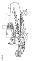
- 2 denotes a combine harvester which is equipped with a harvesting device 4 below a driver's cab 5 and which has two front drivable wheels 6 and two rear controllable wheels 8.
- a threshing drum 12 with a concave 14 to which a tray shaker 16 is connected.
- a feed tray 18 and a cleaning device 20 are provided beneath the tray shaker 16 and can be pressurized with compressed air via a blower 22.
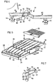
- FIG. 5 only shows a front feed bottom part 38 of a two-part feed bottom 18 according to FIGS. 1, 2, 3, and 4.
- web parts 42 are connected to the hanging strips 34, which are rigidly connected to the front cross frame of the downstream feed bottom part 40.
- the feed tray 18 formed from the two feed tray parts 38 and 40 is swingably supported on front rockers 44 and rear rockers 46, which are continuously driven by a drive device, not shown in the drawing.
- the rear end of the slope strips 34 of the feed bottom part 38 is designed in the form of a nozzle 58 (FIG. 5), which consists of two parallel side parts 48 and 50, an approximately horizontal bottom 52 and a straight one (FIG. 7) or one curved (Fig. 4) rear wall 54 may be formed.
- the end of the upper part of the nozzle 58 is provided with a longitudinal slot 56.
- the nozzle 58 formed from the side parts 48 and 50 of the rear wall 54 and the base 52 can be equipped with a front wall 60 at its front end.
- a feed channel 64 which extends over the entire width of the feed tray 18.
- the feed channel 64 is equipped with one or more inlet connections 66, which is connected to a blower 71 (FIG. 1) via an elastic hose 68, which allows the movement of the feed floor 18.
- Each slope ledge 34 is equipped with the same nozzle 58, which is also connected to the feed channel 64, so that all the nozzles 58 can be acted upon together with compressed air via a single feed channel.
- the feed channel 64 can be made of a circular tube (Fig. 1-4) or a square tube (Fig. 5, 7) may be formed.
- a finger rake 70 is provided, which can be detachably connected to the surface of the slope strips 34 or to the side members 26 and 28. The crop is guided over the finger rake 70 and fed to the subsequent feed bottom part 40.
- the nozzles 58 are integrated in each slope rail 34 and are provided at the rear end of the slope rail. However, it is also possible to equip every second slope ledge 34 with only one nozzle 58.
- the nozzles 58 ' are not located in the hanging strips 34 but in webs 72 which connect the rear end of the feed bottom part 38 to the front end of the feed bottom part 40.
- the webs 72 consist of two parallel side parts 74 and 76, which are delimited by the lower edge of the front slope rail 36 and the upper edge of the subsequent slope rail.
- a nozzle 80 Connected to the side parts 74 and 76 is a nozzle 80 which, as can be seen in FIG. 3, is designed to be inclined to the rear, so that the air jet is directed somewhat upwards and the finger rake 70 and the surface of the nozzle 80 adjoining slope strips 34 are pressurized with compressed air.
- the nozzles 80 of each web 72 are jointly acted upon by compressed air via a feed channel 82, which, as in the exemplary embodiment according to FIG. 4, is connected to the blower 71 via a connecting piece 84 and an elastic hose 86.
- numerous nozzles 88 arranged next to one another are provided below the rear end of the front feed bottom part 38, which act on the surface of the subsequent feed bottom part 40 with compressed air.
- the rear end of the cross member 32 of the front feed bottom part 38 is directly connected to the front cross member 30 of the rear feed bottom part 40.
- the nozzles 88 can be provided between the individual slope strips 34.
- the nozzles 88 like the nozzles 58 already described, are connected together via a feed channel 90 which is connected to the blower 71 via an inlet connection 92 and a hose 94.
- the crop is largely excreted via the concave 14 and passed through a basket splash panel 96 to the front feed bottom part 38. Since the feed tray 18 is brought into a swinging motion via the rockers 44 and 46, the crop that is delivered to the surface of the feed tray part 38 and is still mixed with straw or chaff is directed backwards over the feed tray part until it reaches the area of influence Air nozzles 58 and 80, 88 arrives. Compressed air is applied to the crop in this area, so that the chaff can be separated from the crop on the feed tray 18, which is moved further over the rear feed tray part 40.
- the chaff is blown over the surface of the feed bottom part 40 and gripped by the following blower 22 and then passed over the subsequent cleaning device 20 so that it can then be discharged to the rear.
- a pre-sorting of the harvested crop can take place in the area of the feed bottom 18, so that the subsequent cleaning device 20 is loaded less, which ensures a more effective cleaning of the harvested crop.
Landscapes
- Life Sciences & Earth Sciences (AREA)
- Environmental Sciences (AREA)
- Threshing Machine Elements (AREA)
Claims (6)
Priority Applications (2)
| Application Number | Priority Date | Filing Date | Title |
|---|---|---|---|
| DE8181108620T DE3173652D1 (en) | 1981-10-21 | 1981-10-21 | Grain pan for harvesters |
| EP19810108620 EP0077416B1 (fr) | 1981-10-21 | 1981-10-21 | Table à grain pour moissonneuses |
Applications Claiming Priority (1)
| Application Number | Priority Date | Filing Date | Title |
|---|---|---|---|
| EP19810108620 EP0077416B1 (fr) | 1981-10-21 | 1981-10-21 | Table à grain pour moissonneuses |
Publications (2)
| Publication Number | Publication Date |
|---|---|
| EP0077416A1 EP0077416A1 (fr) | 1983-04-27 |
| EP0077416B1 true EP0077416B1 (fr) | 1986-01-29 |
Family
ID=8187966
Family Applications (1)
| Application Number | Title | Priority Date | Filing Date |
|---|---|---|---|
| EP19810108620 Expired EP0077416B1 (fr) | 1981-10-21 | 1981-10-21 | Table à grain pour moissonneuses |
Country Status (2)
| Country | Link |
|---|---|
| EP (1) | EP0077416B1 (fr) |
| DE (1) | DE3173652D1 (fr) |
Cited By (1)
| Publication number | Priority date | Publication date | Assignee | Title |
|---|---|---|---|---|
| CN102668805A (zh) * | 2011-12-16 | 2012-09-19 | 河南科技大学 | 组合便携式谷物联合收割机 |
Families Citing this family (4)
| Publication number | Priority date | Publication date | Assignee | Title |
|---|---|---|---|---|
| US8651927B1 (en) * | 2012-09-13 | 2014-02-18 | Cnh America Llc | Combine harvester sieve assembly with an integrated air cleaning system |
| GB201221347D0 (en) | 2012-11-28 | 2013-01-09 | Agco As | Crop processing apparatus in a combine harvester |
| US10257983B2 (en) | 2014-12-17 | 2019-04-16 | Agco International Gmbh | Crop processing apparatus in a combine harvester |
| US10806086B2 (en) | 2018-04-18 | 2020-10-20 | Deere & Company | Multi-fan agricultural harvester cleaning system |
Family Cites Families (8)
| Publication number | Priority date | Publication date | Assignee | Title |
|---|---|---|---|---|
| US2228228A (en) * | 1938-10-05 | 1941-01-07 | Ferguson Donald Sinclair | Threshing machine |
| US2694493A (en) * | 1952-02-08 | 1954-11-16 | Carl O Odegarden | Blower attachment for combines |
| US3116236A (en) * | 1960-08-01 | 1963-12-31 | Claas Helmut | Grills of combine harvesters |
| FR1541478A (fr) * | 1966-10-26 | 1968-10-04 | Texas Industries Inc | Batteuse, en particulier moissonneuse-batteuse |
| US3603063A (en) * | 1969-12-10 | 1971-09-07 | Clark E Stroburg | Combine |
| US4265077A (en) * | 1979-08-03 | 1981-05-05 | Deere & Company | Blower system for an axial flow rotary combine cleaning shoe |
| GB2056242B (en) * | 1979-08-14 | 1983-01-19 | Massey Ferguson Services Nv | Crop threshing separating and cleaning apparatus |
| GB2063036B (en) * | 1979-11-14 | 1983-06-29 | Sperry Nv | Combine harvesters |
-
1981
- 1981-10-21 DE DE8181108620T patent/DE3173652D1/de not_active Expired
- 1981-10-21 EP EP19810108620 patent/EP0077416B1/fr not_active Expired
Cited By (1)
| Publication number | Priority date | Publication date | Assignee | Title |
|---|---|---|---|---|
| CN102668805A (zh) * | 2011-12-16 | 2012-09-19 | 河南科技大学 | 组合便携式谷物联合收割机 |
Also Published As
| Publication number | Publication date |
|---|---|
| DE3173652D1 (en) | 1986-03-13 |
| EP0077416A1 (fr) | 1983-04-27 |
Similar Documents
| Publication | Publication Date | Title |
|---|---|---|
| DE60013249T2 (de) | Anpassungsfähigkeit bei axialflussmähdreschern | |
| DE2842702C2 (de) | Reinigungsvorrichtung für Mähdrescher | |
| EP0121094B1 (fr) | Dispositif de nettoyage pour moissonneuse-batteuse | |
| EP2298061B1 (fr) | Procédé de répartition d'un flux de matière sur un champ et dispositif de hachage et de répartition | |
| DE69813696T2 (de) | Reinigungsvorrichtung für Mähdrescher | |
| EP0514820B1 (fr) | Dent, support, dispositif de fixation des dents et séparateur axial | |
| EP0282736B1 (fr) | Dispositif de retour pour moissonneuse-batteuse | |
| EP0694250A1 (fr) | Dispositif de nettoyage | |
| EP0077416B1 (fr) | Table à grain pour moissonneuses | |
| EP1559306B1 (fr) | Distributeur pour améliorer la distribution de produit sur un filtre d'un système de nettoyage | |
| EP3903557B1 (fr) | Moissonneuse-batteuse autonome, ainsi que procédé de récolte | |
| DE60009702T2 (de) | Verbesserung der Fördermittel einer Fruchterntemaschine | |
| EP1378161B1 (fr) | Dispositif pneumatique de tamisage | |
| DE3932945A1 (de) | Reinigungseinrichtung fuer maehdrescher | |
| EP0087488B1 (fr) | Dispositif de nettoyage pour moissonneuses-batteuses | |
| DE2913657A1 (de) | Erntemaschine zur gewinnung von tierfutter (corn-cop-mix) aus maiskolben | |
| EP1820390B1 (fr) | Moissonneuse-batteuse avec zone de séparation multi-étagée | |
| DE3503950C2 (fr) | ||
| EP1820389B1 (fr) | Moissonneuse-batteuse avec zone de séparation multi-étagée | |
| DE19846790A1 (de) | Mähdrescher | |
| DE19815730A1 (de) | Abscheideelement, Abscheidevorrichtung und Erntemaschine | |
| EP2103204B1 (fr) | Moissonneuse-batteuse | |
| DE3804348A1 (de) | Mehrebenen-reinigungseinrichtung fuer maehdrescher | |
| DE1053848B (de) | Anordnung zum Nachdreschen in einer Dreschmaschine | |
| DE102022123506A1 (de) | Mähdrescher mit einer Reinigungsvorrichtung |
Legal Events
| Date | Code | Title | Description |
|---|---|---|---|
| PUAI | Public reference made under article 153(3) epc to a published international application that has entered the european phase |
Free format text: ORIGINAL CODE: 0009012 |
|
| 17P | Request for examination filed |
Effective date: 19821020 |
|
| AK | Designated contracting states |
Designated state(s): AT BE CH DE FR GB IT LI LU NL SE |
|
| EL | Fr: translation of claims filed | ||
| TCNL | Nl: translation of patent claims filed | ||
| ITCL | It: translation for ep claims filed |
Representative=s name: LENZI & C. |
|
| RBV | Designated contracting states (corrected) |
Designated state(s): BE DE FR GB IT SE |
|
| ITF | It: translation for a ep patent filed | ||
| GRAA | (expected) grant |
Free format text: ORIGINAL CODE: 0009210 |
|
| AK | Designated contracting states |
Designated state(s): BE DE FR GB IT SE |
|
| REF | Corresponds to: |
Ref document number: 3173652 Country of ref document: DE Date of ref document: 19860313 |
|
| ET | Fr: translation filed | ||
| PLBE | No opposition filed within time limit |
Free format text: ORIGINAL CODE: 0009261 |
|
| STAA | Information on the status of an ep patent application or granted ep patent |
Free format text: STATUS: NO OPPOSITION FILED WITHIN TIME LIMIT |
|
| 26N | No opposition filed | ||
| PGFP | Annual fee paid to national office [announced via postgrant information from national office to epo] |
Ref country code: GB Payment date: 19890930 Year of fee payment: 9 |
|
| PGFP | Annual fee paid to national office [announced via postgrant information from national office to epo] |
Ref country code: FR Payment date: 19891018 Year of fee payment: 9 |
|
| PGFP | Annual fee paid to national office [announced via postgrant information from national office to epo] |
Ref country code: SE Payment date: 19891019 Year of fee payment: 9 |
|
| PG25 | Lapsed in a contracting state [announced via postgrant information from national office to epo] |
Ref country code: GB Effective date: 19901021 |
|
| PG25 | Lapsed in a contracting state [announced via postgrant information from national office to epo] |
Ref country code: SE Effective date: 19901022 |
|
| GBPC | Gb: european patent ceased through non-payment of renewal fee | ||
| PG25 | Lapsed in a contracting state [announced via postgrant information from national office to epo] |
Ref country code: FR Effective date: 19910628 |
|
| REG | Reference to a national code |
Ref country code: FR Ref legal event code: ST |
|
| PGFP | Annual fee paid to national office [announced via postgrant information from national office to epo] |
Ref country code: BE Payment date: 19921028 Year of fee payment: 12 |
|
| ITTA | It: last paid annual fee | ||
| PGFP | Annual fee paid to national office [announced via postgrant information from national office to epo] |
Ref country code: DE Payment date: 19921211 Year of fee payment: 12 |
|
| PG25 | Lapsed in a contracting state [announced via postgrant information from national office to epo] |
Ref country code: BE Effective date: 19931031 |
|
| BERE | Be: lapsed |
Owner name: DEERE & CY Effective date: 19931031 |
|
| PG25 | Lapsed in a contracting state [announced via postgrant information from national office to epo] |
Ref country code: DE Effective date: 19940701 |
|
| EUG | Se: european patent has lapsed |
Ref document number: 81108620.6 Effective date: 19910603 |