EP0077468A2 - Pressing device for the manufacture of compacts for nuclear fuel - Google Patents
Pressing device for the manufacture of compacts for nuclear fuel Download PDFInfo
- Publication number
- EP0077468A2 EP0077468A2 EP82108684A EP82108684A EP0077468A2 EP 0077468 A2 EP0077468 A2 EP 0077468A2 EP 82108684 A EP82108684 A EP 82108684A EP 82108684 A EP82108684 A EP 82108684A EP 0077468 A2 EP0077468 A2 EP 0077468A2
- Authority
- EP
- European Patent Office
- Prior art keywords
- attachment part
- die
- starting material
- opening
- filling
- Prior art date
- Legal status (The legal status is an assumption and is not a legal conclusion. Google has not performed a legal analysis and makes no representation as to the accuracy of the status listed.)
- Granted
Links
Images

Classifications
-
- B—PERFORMING OPERATIONS; TRANSPORTING
- B30—PRESSES
- B30B—PRESSES IN GENERAL
- B30B15/00—Details of, or accessories for, presses; Auxiliary measures in connection with pressing
- B30B15/30—Feeding material to presses
- B30B15/302—Feeding material in particulate or plastic state to moulding presses
- B30B15/304—Feeding material in particulate or plastic state to moulding presses by using feed frames or shoes with relative movement with regard to the mould or moulds
Definitions
- the invention relates to a pressing device for producing compacts from powdery starting material, in particular powdered nuclear reactor fuel, with a die which is located in a die table and which has a die hole associated with a press ram for receiving powdery starting material, and with a die attached to a movable arm, Filling shoe, which can be moved over the die table and is in contact with the die table, for filling powdered starting material into the die hole, which has an outlet opening facing the die table with a filling aid device and which is connected with a hose to a storage container for powdered starting material provided with a metering device.
- powdery starting material in particular powdered nuclear reactor fuel
- a vibrating grid is arranged in the filling shoe of this commercially available pressing device, which supports the filling of the powdered starting material into the die hole as a filling auxiliary device.
- the storage container for powdered starting material is an open funnel with a flat slide as a metering device for metering the powdered starting material supplied to the filling shoe.
- the vibrating grid in the filling shoe of this pressing device ver However, causes the leakage of substantial amounts of powdery starting material at the seal, which the filling shoe has towards the die table. Furthermore, the transfer of powdered starting material from a storage or transport can into the open funnel causes a strong dust development, which also leads to losses of powdered starting material. Such losses also occur on the slide with which the open funnel is equipped for metering the powdery starting material fed to the filling shoe. '
- the invention is based on the object, remedy here to create and largely avoid dust and powder losses on the pressing device when producing compacts from powdered starting material.
- a pressing device of the type mentioned at the outset is characterized in that a passing wheel is arranged in the outlet opening of the filling shoe as a filling auxiliary device, that a tube is connected between the hose and the storage container as a metering device, in which there is a screw which is coaxial to the tube that the storage container has a base part with a can-like attachment part and with an outlet hole that is arranged eccentrically in the floor with respect to the longitudinal axis of the can-like attachment part and leads to the tube with the screw, that a coupling part sits at the opening of the can-like attachment part, which has a coupling part for opening the can-like attachment part leading, eccentrically arranged to the longitudinal axis of the can-like attachment part is provided and which is assigned a cover part located between the base part and coupling part, which also has an eccentric to the longitudinal axis of the do Sen-like attachment part arranged passage opening is provided, and that the coupling part and the cover part are rotatable relative to each
- the impeller can, for example, be provided with bristles on its circumference, with which it, when it is rotating, passes the powdered starting material into the die hole in the outlet opening of the filling shoe. This prevents vibrations in the filling shoe, which can lead to losses due to the escape of powdered starting material between the filling shoe and matrix table occur.
- the tube with coaxial feed screw connected as a dosing device between the hose and the storage container completely covers this coaxial feed screw and thus also prevents losses of powdered starting material from occurring on the dosing device.
- the can-like attachment part can be, for example, a hollow cylindrical transport or storage box for powdery starting material with a screw cap. After unscrewing the screw cap, the coupling part is screwed onto the box and closed with the cover part. Then the box with the coupling and the lid part is placed on the base part. If the through-hole in the coupling part, the through-hole in the cover part and the outlet hole in the base part are aligned, powdered starting material can get from the transport or storage box into the tube with the coaxial screw to this conveyor screw without the formation of dust and thus without loss of powdery starting material .
- This pressing device also has the advantage that the impeller can be driven without vibrations, so that a renewal of the seal, which is located on the filling shoe towards the die table, is only very rarely required. Furthermore, the impeller and its bearings are subject to much less wear than guides for vibrating grids, so that time-consuming and expensive repair work, which can be associated with a high radiation exposure for the operating personnel, can be avoided with this pressing device.
- the impeller is an impeller that has an axis of rotation that coincides with that of the outlet opening certain plane forms an angle of 90 ° or at least approximately 90 °.
- Such an impeller smashes powder bridges which form in the outlet opening of the filling shoe on the die table and can lead to the die bore not being filled uniformly with powdered starting material.
- the die 1 has a die table 2 and a stand 3.
- the die table 2 there is a die 4 with an open die hole 5 perpendicular to the die table 2.
- the tube 6 is provided with an attachment part 30, into which the interior of the tube 6 opens and which has a vertically downwardly directed pipe socket 11.
- an attachment part 30 into which the interior of the tube 6 opens and which has a vertically downwardly directed pipe socket 11.
- On this pipe socket 11 sits one end of a deformable hose 12 made of polyvinyl chloride, the other end of which sits on a pipe socket 13 of a filling shoe 14.
- This filling shoe 14 rests on the die table 2 and is attached to a two-part arm 15, with which it can be moved over the die table 2 in FIG. 1 from right to left and left to right, i.e. H. back and forth, can be moved.
- the filling shoe 14 has a frustoconical interior, which tapers towards an outlet opening 20, which is directed towards the die table 2.
- the nozzle 13 of the filling shoe 14 opens into this interior.
- An impeller 16 with an axis of rotation is arranged in the outlet opening 20 as a passing wheel, which forms an angle of 90 ° with the plane defined by the outlet opening 20.
- the edges of the impeller 16 facing the die table 2 are flat and flat and lie in the same plane with the flat and flat contact surfaces 14a with which the filling shoe 14 rests on the die table 2.
- the outlet opening 20 is enclosed by an annular felt seal 17 which is embedded in the likewise annular contact surface 14a.
- the impeller 16 is connected to a flexible shaft 18 which is coupled to the shaft of an electric motor, not shown.
- a sleeve 21 On the other end of the tube 6 with the flexible shaft 10 sits a sleeve 21, the cross section of which has a rectangular outer circumference.
- the jacket of this sleeve 21 is provided on the top with a bushing 21a, which is aligned with a bushing 6a in the jacket of the tube 6, which leads to the conveying path of the screw 9.
- On the outside of the sleeve 21 sits at the top a base 22 of a storage container for powdered starting material with a can-like attachment part 23 belonging to the storage container the sleeve 21 and 6a in the casing of the tube 6 are aligned.
- a hollow cylindrical coupling part 24 is screwed to the attachment part 23, which tapers in the shape of a funnel to a passage bore 24a, which is arranged eccentrically to the longitudinal axis 23a of the can-like attachment part 23 on the bottom of the coupling part 24.
- a pot-like cover part 25 which in its bottom also has a passage opening 25a arranged eccentrically to the longitudinal axis 23a of the can-like attachment part 23.
- the cover part 25 closes the through bore 24a in the coupling part 24, as long as the can-like attachment part 23 is not placed on the base part 22.
- Appropriate guiding and locking devices such as punctures, axially directed grooves and associated pins on the base part 22, on the cover part 25 and on the coupling part 24, can achieve that the can-like attachment part 23 can only be placed on the base part 22 such that the outlet bore 22a in the base part 22 is aligned with the passage opening 25a in the cover part 25.
- the locking devices ensure that the can-like attachment part 23 with the coupling part 24 can only be rotated about the longitudinal axis 23a of the can-like attachment part 23 relative to the cover part 25a to such an extent that the outlet bore 24a in the base part 24 is aligned with the passage opening 25a and the outlet bore 22a, when the coupling part 24 with the cover part 25 is placed on the base part 22.
- an upper press ram 31 is indicated in FIG. 1, with the one being filled in the die hole 5 powdery starting material is compacted into a compact.
- a can-like attachment part 23 which contains, for example, UO 2 / PuO 2 powder, is opened with the opening 23 b directed vertically upwards.
- the coupling part 24, on which the cover part 25 is located, is hereby screwed tightly onto the opening 23b.
- the outlet bore 24a in the coupling part 24 is closed by the cover part 25.
- the can-like attachment part 23 with the vertically downward opening 23b and the coupling part 24 together with the cover part 25 is placed on the base part 22, so that the passage opening 25a in the cover part 25 is aligned with the outlet bore 22a in the base part 22.
- the through hole 24a in the coupling part 24 is brought into alignment with the passage opening 25a in the cover part 25.
- the U0 2 / Pu0 2 powder flows loss-free from the can-like attachment part 23 to the feed screw 9 in the tube 6, through which it is also conveyed to the attachment part 30 without loss. From the attachment part 30, the powder again flows loss-free through the hose 12 into the interior of the filling shoe 14 located above the die hole 5, from where it is passed into the die hole 5 with the help of the impeller 16 which is rotating.
- the compact formed in the matrix bore 5 is ejected from the latter onto the die table 2 by a relative movement between the die 4 and the lower ram located in the die bore 5, from which die it is pushed into a storage container, not shown, by the filling shoe 14, which is moved again from right to left, ie from the back to the front, in FIG. 1 on the die table 2.
- the filling shoe 14 In the end position of this movement from right to left, ie from the back to the front, the filling shoe 14 is again above the die hole 5, which is filled again with UO 2 / PuO 2 powder.
- a particularly favorable passing effect is achieved if the blades on the circumference of the impeller 16 form an angle of inclination which is not equal to 90 ° with the plane determined by the outlet opening 15 of the filling shoe 14 and thus also with the plane determined by the die table 2.
- the filling level of the U0 2 / Pu0 2 powder in the filling shoe 14 is always the same, so that the filling quantity of powder in the die bore 5 always has the same value. It is thereby achieved that the height and weight of all compacts, which are compacted to a uniform density by the upper punch 30, are always the same. It is therefore advantageous if an electrical capacitor electrode is arranged in the filling shoe 14. Such an electrical capacitor electrode is advantageously the metal bearing 19 of the impeller 16 located in the interior of the filling shoe 14, which is in contact with the metals NEN die table 2 forms a capacitive level indicator as a counter electrode. This capacitive level indicator can be connected as a sensor to a controller, not shown, with which the speed of the electric motor, which is also not shown and which is coupled to the flexible shaft 10 of the feed screw 9, is regulated.
- the tube 6 and the hose 12 made of plastic, for. B. polyethylene, while the screw 6 located in the tube 9 is made of stainless steel.
- the housing of the filling shoe 14 is also made of plastic, preferably polyethylene.
- the filling shoe 14 is pneumatically pressed against the die table 2 by means of a lever 32 articulated on the arm 15 with a constant contact pressure. As a result, uniform wear of the felt seal 17 in the filling shoe 14 is achieved without any manual adjustment of this seal 17. It is expedient if the filling shoe 14 is mounted on the movable arm 15 via ball bearings 28 about an axis of rotation 29 transversely to its direction of displacement on the die table 2. As a result, the filler shoe 14 can better follow the oscillating movements of the die table 2, so that the felt seal 17 in the filler shoe 14 fits well on the die table even during such swinging movements 2 is present and any losses of powdered starting material which penetrates this seal 17 can be avoided.
Landscapes
- Engineering & Computer Science (AREA)
- Mechanical Engineering (AREA)
- Basic Packing Technique (AREA)
- Powder Metallurgy (AREA)
Abstract
Preßvorrichtung zum Herstellen von Preßlingen aus pulverförmigem Ausgangsstoff, insbesondere pulverförmigem Kernreaktorbrennstoff, mit einer Matrize, die sich in einem Matrizentisch befindet und die eine einem Preßstempel zugeordnete Matrizenbohrung zur Aufnahme von pulverförmigem Ausgangsstoff aufweist, sowie mit einem an einem beweglichen Arm angebrachten, über den Matrizentisch verschiebbaren, am Matrizentisch anliegenden Füllschuh zum Einfüllen von pulverförmigem Ausgangsstoff in die Matrizenbohrung, welcher eine zum Matrizentisch gerichtete Auslauföffnung mit einer Einfüllhilfseinrichtung aufweist und weicher mit einem Schlauch an einem mit einer Dosiereinrichtung versehenen Vorratsbehälter für pulverförmigen Ausgangsstoff angeschlossen ist. Es ist vorgesehen, daß in der Auslauföffnung (20) des Füllschuhes (14) als Einfüllhilfseinrichtung ein Passierrad (16) angeordnet ist, daß zwischen Schlauch (12) und Vorratsbehälter als Dosiereinrichtung ein Rohr (6) geschaltet ist, in dem sich eine zum Rohr (6) koaxiale Förderschraube (9) befindet, daß der Vorratsbehälter ein Grundteil (22) mit dosenartigem Aufsetzteil (23) und mit im Boden bezüglich der Längsachse (23a) des dosenartigen Aufsetzteiles (23) exzentrisch angeordneter, zum Rohr (6) mit der Förderschraube (9) führender Auslaufbohrung (22a) aufweist, daß an der Öffnung (23b) des dosenartigen Aufsetzteiles (23) ein Kupplungsteil (24) sitzt, welches mit einer zur Öffnung (23b) des dosenartigen Aufsetzteiles (23) führenden, exzentrisch zur Längsachse (23a) des dosenartigen Aufsetzteiles (23) angeordneten Durchtrittsbohrung (24a) versehen ist und dem ein zwischen Grundteil (22) und Kupplungsteil (24) befindliches Deckelteil (25) zugeordnet ist, das ebenfalls mit einer exzentrisch zur Längsachse (23a) des dosenartigen Aufsetzteiles (23) angeordneten Durchtrittsöffnung (25a) versehen ist, und daß das Kupplungsteil (24) und das Deckelteil (25) relativ zueinander um die Längsachse (23a) des dosenartigen Aufsetzteiles (23) in eine Position verdrehbar sind, in der die Durchtrittsöffnung (25a) im Deckelteil (25) und die Auslaufbohrung (22a) im Grundteil (22) fluchten.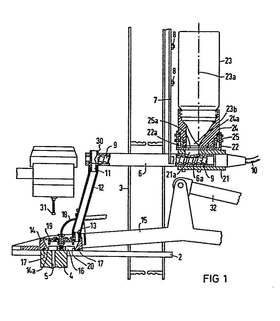
Description
Die Erfindung betrifft eine Preßvorrichtung zum Herstellen von Preßlingen aus pulverförmigem Ausgangsstoff, insbesondere pulverförmigem Kernreaktorbrennstoff, mit einer Matrize, die sich in einem Matrizentisch befindet und die eine einem Preßstempel zugeordnete Matrizenbohrung zur Aufnahme von pulverförmigem Ausgangsstoff aufweist, sowie mit einem an einem beweglichen Arm angebrachten, über den Matrizentisch verschiebbaren, am Matrizentisch anliegenden Füllschuh zum Einfüllen von pulverförmigem Ausgangsstoff in die Matrizenbohrung, welcher eine zum Matrizentisch gerichtete Auslauföffnung mit einer Einfüllhilfseinrichtung aufweist und welcher mit einem Schlauch an einem mit einer Dosiereinrichtung versehenen Vorratsbehälter für pulverförmigen Ausgangsstoff angeschlossen ist.-.The invention relates to a pressing device for producing compacts from powdery starting material, in particular powdered nuclear reactor fuel, with a die which is located in a die table and which has a die hole associated with a press ram for receiving powdery starting material, and with a die attached to a movable arm, Filling shoe, which can be moved over the die table and is in contact with the die table, for filling powdered starting material into the die hole, which has an outlet opening facing the die table with a filling aid device and which is connected with a hose to a storage container for powdered starting material provided with a metering device.
Eine derartige Preßvorrichtung ist bereits im Handel. Im Füllschuh dieser im Handel befindlichen Preßvorrichtung ist ein Rüttelgitter angeordnet, das als Einfüllhilfseinrichtung das Einfüllen des pulverförmigen Ausgangsstoffes in die Matrizenbohrung unterstützt. Ferner ist der Vorratsbehälter für pulverförmigen Ausgangsstoff ein offener Trichter mit einem flachen Schieber als Dosiereinrichtung zum Dosieren des dem Füllschuh zugeführten pulverförmigen Ausgangsstoffes.Such a pressing device is already on the market. A vibrating grid is arranged in the filling shoe of this commercially available pressing device, which supports the filling of the powdered starting material into the die hole as a filling auxiliary device. Furthermore, the storage container for powdered starting material is an open funnel with a flat slide as a metering device for metering the powdered starting material supplied to the filling shoe.
Das Rüttelgitter im Füllschuh dieser Preßvorrichtung verursacht jedoch das Austreten erheblicher'Verlustmengen pulverförmigen Ausgangsstoffes an der Dichtung, die der Füllschuh zum Matrizentisch hin aufweist. Ferner verursacht das Umfüllen von pulverförmigem Ausgangsstoff aus einer Lager- oder Transportdose in den offenen Trichter eine starke Staubentwicklung, die ebenfalls zu Verlusten an pulverförmigem Ausgangsstoff führt. Derartige Verluste treten überdies auch am Schieber auf, mit dem der offene Trichter zum Dosieren des dem Füllschuh zugeführten pulverförmigen Ausgangsstoffes ausgerüstet ist.' The vibrating grid in the filling shoe of this pressing device ver However, causes the leakage of substantial amounts of powdery starting material at the seal, which the filling shoe has towards the die table. Furthermore, the transfer of powdered starting material from a storage or transport can into the open funnel causes a strong dust development, which also leads to losses of powdered starting material. Such losses also occur on the slide with which the open funnel is equipped for metering the powdery starting material fed to the filling shoe. '
Die besagten Verluste sind insbesondere beim Verarbeiten von pulverförmigem Kernreaktorbrennstoff wie U02- oder UO2/PuO2-Pulver von besonderer Bedeutung, da diese pulverförmigen Kernreaktorbrennstoffe nicht nur sehr teuer, sondern auch toxisch und radioaktiv sind.The losses mentioned are particularly important when processing powdered nuclear reactor fuel such as U0 2 or UO 2 / PuO 2 powder, since these powdered nuclear reactor fuels are not only very expensive, but also toxic and radioactive.
Dies gilt insbesondere für plutoniümhaltige pulverförmige Kernreaktorbrennstoffe, die zur Vermeidung von toxischer und radioaktiver Belastung von Bedienungspersonal grundsätzlich in sogenannten Handschuhkästen verarbeitet wer- den, deren Innenraum von der äußeren Umgebung staubdicht abgeschlossen ist.This applies in particular to powdered nuclear reactor fuels containing plutonium, which are generally processed in so-called glove boxes to avoid toxic and radioactive contamination of the operating personnel, the interior of which is dust-tight from the outside environment.
Da die im Handel befindliche Preßvorrichtung eine Staubentwicklung und einen Pulveraustritt am Füllschuh zeigt, die für die Verarbeitung pulverförmiger Kernbrennstoffe zu groß sind, verursacht diese Preßvorrichtung bei Aufstellung und Betrieb in einem Handschuhkasten erhebliche Reinigungsarbeiten in diesem Handschuhkasten, die regelmäßig wiederkehren und die z. B. beim Verarbeiten plutoniumhaltiger pulverförmiger Kernreaktorbrennstoffe zu einer hohen Strahlenbelastung-des Bedienungspersonals führen können.Since the press device on the market shows a dust development and a powder discharge on the filling shoe, which are too large for the processing of powdered nuclear fuels, this pressing device causes considerable cleaning work in this glove box during installation and operation in a glove box, which regularly recur and the z. B. when processing plutonium-containing powdered nuclear reactor fuels can lead to high radiation exposure - the operating personnel.
Der Erfindung liegt die Aufgabe zugrunde, hier Abhilfe zu schaffen und Staubentwicklung und Pulververluste an der Preßvorrichtung beim Herstellen von Preßlingen aus pulverförmigen Ausgangsstoff weitgehend zu vermeiden.The invention is based on the object, remedy here to create and largely avoid dust and powder losses on the pressing device when producing compacts from powdered starting material.
Zur Lösung der dieser Aufgabe ist eine Preßvorrichtung der eingangs erwähnten Art erfindungsgemäß dadurch gekennzeichnet, daß in der Auslauföffnung des Füllschuhs als Einfüllhilfseinrichtung ein Passierrad angeordnet ist, daß zwischen Schlauch und Vorratsbehälter als Dosiereinrichtung ein Rohr geschaltet ist, in dem sich eine zum Rohr koaxiale Förderschraube befindet, daß der Vorratsbehälter ein Grundteil mit dosenartigem Aufsetzteil und mit im Boden bezüglich der Längsachse des dosenartigen Aufsetzteiles exzentrisch angeordneter, zum Rohr mit der Förderschraube führender Auslaufbohrung aufweist, daß an der Öffnung des dosenartigen Aufsetzteiles ein Kupplungsteil sitzt, welches mit einer zur Öffnung des dosenartigen Aufsetzteiles führenden, exzentrisch zur Längsachse des dosenartigen Aufsetzteiles angeordneten Durchtrittsbohrung versehen ist und dem ein zwischen Grundteil und Kupplungsteil befindliches Deckelteil zugeordnet ist, das ebenfalls mit einer exzentrisch zur Längsachse des dosenartigen Aufsetzteiles angeordneten Durchtrittsöffnung versehen ist, und daß das Kupplungsteil und das Deckelteil relativ zueinander um die Längsachse des dosenartigen Aufsetzteiles in eine Position verdrehbar sind, in der die Durchtrittsbohrung im Kupplungsteil mit der Durchtrittsöffnung im Deckelteil und der Auslaufbohrung im Grundteil fluchten.To achieve this object, a pressing device of the type mentioned at the outset is characterized in that a passing wheel is arranged in the outlet opening of the filling shoe as a filling auxiliary device, that a tube is connected between the hose and the storage container as a metering device, in which there is a screw which is coaxial to the tube that the storage container has a base part with a can-like attachment part and with an outlet hole that is arranged eccentrically in the floor with respect to the longitudinal axis of the can-like attachment part and leads to the tube with the screw, that a coupling part sits at the opening of the can-like attachment part, which has a coupling part for opening the can-like attachment part leading, eccentrically arranged to the longitudinal axis of the can-like attachment part is provided and which is assigned a cover part located between the base part and coupling part, which also has an eccentric to the longitudinal axis of the do Sen-like attachment part arranged passage opening is provided, and that the coupling part and the cover part are rotatable relative to each other about the longitudinal axis of the can-like attachment part in a position in which the through hole in the coupling part with the through opening in the cover part and the outlet bore in the base part are aligned.
Das Passierrad kann beispielsweise auf seinem Umfang mit Borsten versehen sein, mit denen es, wenn es sich in Umdrehung befindet, in der Auslauföffnung des Füllschuhes den pulverförmigen Ausgangsstoff in die Matrizenbohrung passiert. Hierbei werden Rüttelbewegungen im Füllschuh vermieden, die dazu führen können, daß Verluste durch Austritt von pulverförmigem Ausgangsstoff zwischen Füllschuh und Matrizentisch auftreten.The impeller can, for example, be provided with bristles on its circumference, with which it, when it is rotating, passes the powdered starting material into the die hole in the outlet opening of the filling shoe. This prevents vibrations in the filling shoe, which can lead to losses due to the escape of powdered starting material between the filling shoe and matrix table occur.
Das als Dosiereinrichtung zwischen Schlauch und Vorratsbehälter geschaltete Rohr mit koaxialer Förderschraube deckt diese koaxiale Förderschraube vollkommen ab und verhindert so ebenfalls, daß an der Dosiereinrichtung Verluste an pulverförmigem Ausgangsstoff auftreten.The tube with coaxial feed screw connected as a dosing device between the hose and the storage container completely covers this coaxial feed screw and thus also prevents losses of powdered starting material from occurring on the dosing device.
Bei dem dosenartigen Aufsetzteil kann es sich beispielsweise um eine hohlzylinderförmige Transport- oder Lagerdose für pulverförmigen Ausgangsstoff mit einem Schraubdeckel handeln. Nach dem Abschrauben des Schraubdeckels wird das Kupplungsteil an der Dose festgeschraubt und mit dem Deckelteil verschlossen. Sodann wird die Dose mit dem Kupplungs- und dem Deckelteil auf das Grundteil aufgesetzt. Sind die Durchtrittsbohrung im Kupplungsteil, die Durchtrittsöffnung im Deckelteil und die Auslaufbohrung im Grundteil zum Fluchten gebracht, kann pulverförmiger Ausgangsstoff ohne Staubbildung und damit ohne Verluste an pulverförmigem Ausgangsstoff aus der Transport- oder Lagerdose in das Rohr mit der koaxialen Förderschraube zu dieser Fördersclir-aube gelangen.The can-like attachment part can be, for example, a hollow cylindrical transport or storage box for powdery starting material with a screw cap. After unscrewing the screw cap, the coupling part is screwed onto the box and closed with the cover part. Then the box with the coupling and the lid part is placed on the base part. If the through-hole in the coupling part, the through-hole in the cover part and the outlet hole in the base part are aligned, powdered starting material can get from the transport or storage box into the tube with the coaxial screw to this conveyor screw without the formation of dust and thus without loss of powdery starting material .
Diese Preßeinrichtung hat ferner den Vorteil, daß das Passierrad rüttelfrei angetrieben werden kann, so daß ein Erneuern der Dichtung, die sich am Füllschuh zum Matrizentisch hin befindet, nur sehr selten erforderlich ist. Ferner unterliegen das Passierrad und seine Lager sehr viel weniger dem Verschleiß als Führungen für Rüttelgitter, so daß mit dieser Preßeinrichtung zeitraubende und aufwendige Reparaturarbeiten, die mit einer hohen Strahlenbelastung für das Bedienungspersonal verbunden sein können, vermieden werden.This pressing device also has the advantage that the impeller can be driven without vibrations, so that a renewal of the seal, which is located on the filling shoe towards the die table, is only very rarely required. Furthermore, the impeller and its bearings are subject to much less wear than guides for vibrating grids, so that time-consuming and expensive repair work, which can be associated with a high radiation exposure for the operating personnel, can be avoided with this pressing device.
Von Vorteil ist es, wenn das Passierrad ein Flügelrad ist, das eine Drehachse hat, die mit der von der Auslauföffnung bestimmten Ebene einen Winkel von 90° oder wenigstens annähernd von 90° bildet. Ein derartiges Flügelrad zerschlägt Pulverbrücken, die sich in der Auslauföffnung des Füllschuhs auf dem Matrizentisch ausbilden und dazu führen können, daß die Matrizenbohrung nicht gleichmäßig mit pulverförmigem Ausgangsstoff gefüllt wird.It is advantageous if the impeller is an impeller that has an axis of rotation that coincides with that of the outlet opening certain plane forms an angle of 90 ° or at least approximately 90 °. Such an impeller smashes powder bridges which form in the outlet opening of the filling shoe on the die table and can lead to the die bore not being filled uniformly with powdered starting material.
Die Erfindung und ihre Vorteile seien anhand der Zeichnung an einem Ausführungsbeispiel näher erläutert:
- Fig. 1 zeigt einen Ausschnitt aus einer erfindungsgemäßen Preßvorrichtungmit zum Teil in Längsrichtung geschnittenen Einzelteilen.
- Fig. 2 zeigt die Draufsicht auf ein Einzelteil nach Fig. 1.
- Fig. 1 shows a section of a pressing device according to the invention with parts cut partly in the longitudinal direction.
- FIG. 2 shows the top view of an individual part according to FIG. 1.
Die Preßvorrichtung nach Fig. 1 weist einen Matrizentisch 2 und ein Stativ 3 auf. Im Matrizentisch 2 befindet sich eine Matrize 4 mit einer zum Matrizentisch 2 senkrechten offenen Matrizenbohrung 5.1 has a die table 2 and a
Am Stativ 3 ist eini:waagerecht angeordnetes Rohr 6 über einen Rahmen 7 mit Schrauben 8 gehaltert. In diesem Rohr 6 befindet sich eine koaxiale Förderschraube 9, mit der das Rohr 6 zusammen eine Dosiereinrichtung bildet. An einem Ende dieser Förderschraube 9 ist eine biegsame Welle 10 angeschlossen, die mit.der Welle eines nicht dargestellten Elektromotors gekoppelt ist.On the
An einem Ende ist das Rohr 6 mit einem Ansatzteil 30 versehen, in den der Innenraum des Rohres 6 mündet und der einen vertikal nach unten gerichteten Rohrstutzen 11 aufweist. Auf diesem Rohrstutzen 11 sitzt das eine Ende eines verformbaren Schlauches 12 aus Polivinylchlorid, dessen anderes Ende auf einem Rohrstutzen 13 eines Füllschuhes 14 sitzt.At one end, the tube 6 is provided with an
Dieser Füllschuh 14 liegt am Matrizentisch 2 an und ist an einem zweiteiligen Arm 15 angebracht, mit dem er über den Matrizentisch 2 in der Fig. 1 von rechts nach links und von links nach rechts,d. h. vor und zurück,verschoben werden kann.This filling
Der Füllschuh 14 weist einen kegelstumpfförmigen Innenraum auf, welcher sich zu einer Auslauföffnung 20 hin verjüngt, die zum Matrizentisch 2 gerichtet ist. In diesen Innenraum mündet der Stutzen 13 des Füllschuhes 14. In der Auslauföffnung 20 ist als Passierrad ein Flügelrad 16 mit einer Drehachse angeordnet, die mit der von der Auslauföffnung 20 bestimmten Ebene einen Winkel von 90° bildet. Die dem Matrizentisch 2 zugewandten-Kanten des Flügelrades 16 sind flach und eben und liegen mit den flachen und ebenen Anlageflächen 14a, mit denen der Füllschuh 14 am Matrizentisch 2 anliegt, in derselben Ebene. Die Auslauföffnung 20 ist von einer ringförmigen Filzdichtung 17 umschlossen, die in der ebenfalls ringförmigen Anlagefläche 14a eingebettet ist. Das Flügelrad 16 ist an einer biegsamen Welle 18 angeschlossen, die mit der Welle eines nicht dargestellten Elektromotors gekoppelt ist.The
Auf dem anderen Ende des Rohres 6 mit der biegsamen Welle 10 sitzt eine Hülse 21, deren Querschnitt einen rechteckigen Außenumfang hat. Der Mantel dieser Hülse 21 ist auf der Oberseite mit einer Durchführung 21a versehen,.die mit einer Durchführung 6a im Mantel des Rohres 6 fluchtet, die zu dem Fördergang der Förderschraube 9 führt. Auf der Außenseite der Hülse 21 sitzt oben ein Grundteil 22 eines Vorratsbehälters für pulverförmigen Ausgangsstoff mit einem zum Vorratsbehälter gehörenden dosenartigen Aufsetzteil 23. Im Boden des Grundteils-22 befindet sich exzentrisch zur Längsachse 23a des Aufsetzteiles 23 eine Auslaufbohrung 22a, die mit den Durchführungen 21a in der Hülse 21 und 6a im Mantel des Rohres 6 fluchtet.On the other end of the tube 6 with the
An der Öffnung 23b des dosenartigen Aufsetzteiles 23 ist ein hohlzylinderförmiges Kupplungsteil 24 am Aufsetzteil 23 festgeschraubt, welches sich innen trichterförmig zu einer Durchtrittsbohrung 24a verjüngt, die exzentrisch zur Längsachse 23a des dosenartigen Aufsetzteiles 23 am Boden des Kupplungsteiles 24 angeordnet ist.At the opening 23b of the can-
Zwischen dem Kupplungsteil 24 und dem Grundteil 22 befindet sich ein topfartiges Deckelteil 25, das in seinem Boden ebenfalls eine zur Längsachse 23a des dosenartigen Aufsetzteiles 23 exzentrisch angeordnete Durchtrittsöffnung 25a aufweist.Between the
Das Deckelteil 25 verschließt die Durchtrittsbohrung 24a im Kupplungsteil 24, so lange das dosenartige Aufsetzteil 23 nicht auf dem Grundteil 22 aufgesetzt ist.The
Durch entsprechende Führungs- und Verriegelungseinrichtungen, wie Einstiche, axial gerichtete Nuten und zugeordnete Stifte am Grundteil 22, am Deckelteil 25 und am Kupplungsteil 24 kann erreicht werden, daß das dosenartige Aufsetzteil 23 nur so auf das Grundteil 22 aufgesetzt werden kann, daß die Auslaufbohrung 22a im Grundteil 22 mit der.Durchtrittsöffnung 25a im Deckelteil 25 fluchtet. Die Verriegelungseinrichtungen sorgen dafür, daß das dosenartige Aufsetzteil 23 mit dem Kupplungsteil 24 nur dann um die Längsachse 23a des dosenartigen Aufsetzteiles 23 relativ zum Deckelteil 25a soweit verdreht werden kann, daß die Auslaufbohrung 24a im Grundteil 24 mit der Durchtrittsöffnung 25a und der Auslaufbohrung 22a fluchtet, wenn das Kupplungsteil 24 mit dem Deckelteil 25 auf dem Grundteil 22 aufgesetzt ist.Appropriate guiding and locking devices, such as punctures, axially directed grooves and associated pins on the
Ober der Matrizenbohrung 5 in der Matrize 4 im Matrizentisch 2 ist in Fig. 1 noch ein oberer Preßstempel 31 angedeutet, mit dem in der Matrizenbohrung 5 eingefüllter pulverförmiger Ausgangsstoff zu einem Preßling kompaktiert wird.Above the die hole 5 in the die 4 in the die table 2, an
Zum Betreiben der Preßvorrichtung nach Fig. 1 und Fig. 2 wird ein dosenartiges Aufsetzteil 23, welches beispielsweise UO2/PuO2-Pulver enthält, mit vertikal nach oben gerichteter Öffnung 23b geöffnet. Hiermit wird an der öffnung 23b das Kupplungsteil 24, an dem sich das Deckelteil 25 befindet, festgeschraubt. Hierbei ist die Auslaufbohrung 24a im Kupplungsteil 24 durch das Deckelteil 25 verschlossen.1 and 2, a can-
Sodann wird das dosenartige Aufsetzteil 23 mit vertikal nach unten gerichteter Öffnung 23b und dem Kupplungsteil 24 samt Deckelteil 25 auf das Grundteil 22 aufgesetzt, so daß die Durchtrittsöffnung 25a im Deckelteil 25 mit der Auslaufbohrung 22a im Grundteil 22 fluchtet. Durch Verdrehen des dosenartigen Aufsetzteiles 23 mit dem Kupplungsteil 24 um die Längsachse 23a des dosenartigen Aufsetzteiles 23 bezüglich des Deckelteiles 25 wird die Durchtrittsbohrung 24a im Kupplungsteil 24 zum Fluchten mit der Durchtrittsöffnung 25a im Deckelteil 25 gebracht. Dadurch rieselt das U02/Pu02-Pulver verlustfrei aus dem dosenartigen Aufsetzteil 23 zur Förderschraube 9 im Rohr 6, durch die es ebenfalls verlustfrei zum Ansatzteil 30 gefördert wird. Aus dem Ansatzteil 30 rieselt das Pulver wiederum verlustfrei durch den Schlauch 12 in den Innenraum des über der Matrizenbohrung 5 befindlichen Füllschuhs 14, von wo es mit Hilfe des in Umdrehung befindlichen Flügelrades 16 in die Matrizenbohrung 5 passiert wird.Then the can-
Sodann wird der Füllschuh 14 mit dem Arm 15 in der Fig. 1 auf dem Matrizentisch 2 nach rechts d. h. nach hinten geschoben, so daß die bis zum oberen Rand mit pulverförmigem Ausgangsstoff gefüllte Matrizenbohrung 5 freigegeben wird.Anschließend wird der obere Preßstempel 31 in die Matrizenbohrung 5 hineingeschoben und das in der Matrizenbohrung 5 befindliche Pulver unter Ausbildung eines Preßlings gegen einen in der Matrizenbohrung 5 befindlichen, in Fig. 1 nicht dargestellten unteren Preßstempel gepreßt. Nach rlem Rückfahren des oberen Preßstempels 31 in seine in Fig. 1 dargestellte Ausgangsstellung wird durch eine Relativbewegung zwischen der Matrize 4 und dem in der Matrizenbohrung 5 befindlichen,unteren Preßstempel der in der Matrizenbohrung 5 ausgebildete Preßling aus dieser auf den Matrizentisch 2 ausgestoßen, von dem er durch den Füllschuh 14, der in Fig. 1 auf dem Matrizentisch 2 wieder von rechts nach links d. h. von hinten nach vorn bewegt wird, in einen nicht dargestellten Vorratsbehälter geschoben wird. In der Endlage dieser von rechts nach links d. h. von hinten nach vorn geführten Bewegung befindet sich der Füllschuh 14 wieder über der Matrizenbohrung 5, die von neuem mit UO2/PuO2-Pulver gefüllt wird.Then the
Eine besonders günstige Passierwirkung wird erzielt., wenn die Flügel am Umfang des Flügelrades 16 mit der von der Auslauföffnung 15 des Füllschuhes 14 und damit auch mit der vom Matrizentisch 2 bestimmten Ebene einen Neigungswinkel bilden, der ungleich 90° ist.A particularly favorable passing effect is achieved if the blades on the circumference of the
Es ist vorteilhaft, wenn der Füllstand des U02/Pu02-Pulvers im Füllschuh 14 stets gleich hoch ist, so daß die Füllmenge an Pulver in der Matrizenbohrung 5 auch stets den gleichen Wert hat. Dadurch wird erreicht, daß Höhe und Gewicht aller Preßlinge, die durch den Oberstempel 30 auf eine gleichmäßige Dichte kompaktiert werden, stets gleich sind. Deshalb ist es vorteilhaft, wenn im Füllschuh 14 eine elektrische Kondensatorelektrode angeordnet ist. Eine solche elektrische Kondensatorelektrode ist günstigerweise das im Innenraum des Füllschuhes 14 befindliche metallene Lager 19 des Flügelrades 16, das mit dem metallenen Matrizentisch 2 als Gegenelektrode einen kapazitiven Füllstandsanzeiger bildet. Dieser kapazitive Füllstandsanzeiger kann als Meßfühler mit einem nicht dargestellten Regler verbunden sein, mit dem die Drehzahl des ebenfalls nicht dargestellten, mit der biegsamen Welle 10 der Förderschraube 9 gekoppelten Elektromotors geregelt wird.It is advantageous if the filling level of the U0 2 / Pu0 2 powder in the
Zur Vermeidung von metallischem Abrieb, der in den pulverförmigen Ausgangsstoff gelangen und dort eventuell stören könnte, ist es günstig, wenn das Rohr 6 und der Schlauch 12 aus Kunststoff, z. B. Polyäthylen bestehen, während die im Rohr 6 befindliche Förderschraube 9 aus Edelstahl gefertigt ist.To avoid metallic abrasion that could get into the powdered starting material and possibly interfere there, it is advantageous if the tube 6 and the
Ebenfalls zur Vermeidung von metallischem Abrieb und zur erleichterten Ausbildung eines kapazitiven Füllstandsanzeigers ist es günstig, wenn das Gehäuse des Füllschuhes 14 ebenfalls aus Kunststoff, vorzugsweise Polyäthylen, besteht.Also to avoid metallic abrasion and to facilitate the formation of a capacitive level indicator, it is advantageous if the housing of the filling
Der Füllschuh 14 wird durch einen am Arm 15 angelenkten Hebel 32 pneumatisch mit stets gleichbleibendem Anpreßdruck gegen den Matrizentisch 2 gepreßt. Hierdurch wird eine gleichmäßige Abnutzung der Filzdichtung 17 im Füllschuh 14 ohne irgendeine manuelle Nachstellung dieser Dichtung 17 erzielt. Günstig ist es, wenn der Füllschuh 14 über Kugellager.28 um eine Drehachse 29 quer zu seiner Verschieberichtung auf dem Matrizentisch 2 drehbar am beweglichen Arm 15 gelagert ist. Hierdurch kann der Füllschuh 14 Schwingbewegungen des Matrizentisches 2 besser folgen, so daß auch während solcher Schwingbewegungen die Filzdichtung 17 im Füllschuh 14 satt am Matrizentisch 2 anliegt und irgendwelche Verluste an pulverförmigem Ausgangsmaterial, das diese Dichtung 17 durchdringt, vermieden werden.The filling
Claims (7)
Applications Claiming Priority (2)
| Application Number | Priority Date | Filing Date | Title |
|---|---|---|---|
| DE3139150A DE3139150C1 (en) | 1981-10-01 | 1981-10-01 | Pressing device for producing compacts from powdery starting material, in particular powdery nuclear reactor fuel |
| DE3139150 | 1981-10-01 |
Publications (3)
| Publication Number | Publication Date |
|---|---|
| EP0077468A2 true EP0077468A2 (en) | 1983-04-27 |
| EP0077468A3 EP0077468A3 (en) | 1983-07-06 |
| EP0077468B1 EP0077468B1 (en) | 1986-02-05 |
Family
ID=6143203
Family Applications (1)
| Application Number | Title | Priority Date | Filing Date |
|---|---|---|---|
| EP82108684A Expired EP0077468B1 (en) | 1981-10-01 | 1982-09-20 | Pressing device for the manufacture of compacts for nuclear fuel |
Country Status (5)
| Country | Link |
|---|---|
| US (1) | US4443174A (en) |
| EP (1) | EP0077468B1 (en) |
| JP (1) | JPS5870996A (en) |
| BR (1) | BR8205720A (en) |
| DE (2) | DE3139150C1 (en) |
Cited By (3)
| Publication number | Priority date | Publication date | Assignee | Title |
|---|---|---|---|---|
| EP0151770A3 (en) * | 1984-02-13 | 1985-10-09 | Alkem Gmbh | Pressing device for the manufacture of compacts for nuclear fuel |
| DE3545494A1 (en) * | 1985-12-20 | 1987-07-02 | Alkem Gmbh | Conveyor device for nuclear fuel powder |
| DE4125935A1 (en) * | 1991-08-05 | 1993-02-11 | Siemens Ag | METHOD AND DEVICE FOR PROCESSING POWDER FROM A DISPENSING STATION TO A RECEPTION STATION |
Family Cites Families (9)
| Publication number | Priority date | Publication date | Assignee | Title |
|---|---|---|---|---|
| GB191226668A (en) * | 1912-11-20 | 1913-09-18 | Wesley Hazard Holmes | Improvements in and relating to Measuring Faucets. |
| US2839787A (en) * | 1954-07-19 | 1958-06-24 | Western Electric Co | Apparatus for molding powdered granular material into preformed articles |
| US4005956A (en) * | 1973-04-11 | 1977-02-01 | Inoue-Japax Research Incorporated | Powder activation and integrated powder metallurgy system |
| US3832107A (en) * | 1973-06-29 | 1974-08-27 | United Aircraft Corp | Apparatus for making articles from particulate matter |
| IT1006262B (en) * | 1974-02-04 | 1976-09-30 | Bras Spa | FLUID DOSER DISTRIBUTOR |
| DE2544609C3 (en) * | 1975-10-06 | 1984-11-08 | Kautex Werke Reinold Hagen Gmbh, 5300 Bonn | Device for influencing the length of a preform made of thermoplastic material |
| GB1556827A (en) * | 1976-08-13 | 1979-11-28 | British Nuclear Fuels Ltd | Powder compacting presses |
| DE2646910A1 (en) * | 1976-10-18 | 1978-04-20 | Albrecht Bruno Kg | Sealing cap for tubes and bottles - is in two parts moved in relation to each other to open outlet |
| US4174938A (en) * | 1977-02-04 | 1979-11-20 | Westinghouse Electric Corp. | Remote nuclear green pellet processing apparatus |
-
1981
- 1981-10-01 DE DE3139150A patent/DE3139150C1/en not_active Expired
-
1982
- 1982-09-20 DE DE8282108684T patent/DE3268969D1/en not_active Expired
- 1982-09-20 EP EP82108684A patent/EP0077468B1/en not_active Expired
- 1982-09-23 US US06/422,180 patent/US4443174A/en not_active Expired - Fee Related
- 1982-09-30 BR BR8205720A patent/BR8205720A/en unknown
- 1982-09-30 JP JP57172509A patent/JPS5870996A/en active Pending
Cited By (3)
| Publication number | Priority date | Publication date | Assignee | Title |
|---|---|---|---|---|
| EP0151770A3 (en) * | 1984-02-13 | 1985-10-09 | Alkem Gmbh | Pressing device for the manufacture of compacts for nuclear fuel |
| DE3545494A1 (en) * | 1985-12-20 | 1987-07-02 | Alkem Gmbh | Conveyor device for nuclear fuel powder |
| DE4125935A1 (en) * | 1991-08-05 | 1993-02-11 | Siemens Ag | METHOD AND DEVICE FOR PROCESSING POWDER FROM A DISPENSING STATION TO A RECEPTION STATION |
Also Published As
| Publication number | Publication date |
|---|---|
| BR8205720A (en) | 1983-09-06 |
| US4443174A (en) | 1984-04-17 |
| JPS5870996A (en) | 1983-04-27 |
| DE3268969D1 (en) | 1986-03-20 |
| DE3139150C1 (en) | 1983-05-19 |
| EP0077468B1 (en) | 1986-02-05 |
| EP0077468A3 (en) | 1983-07-06 |
Similar Documents
| Publication | Publication Date | Title |
|---|---|---|
| DE2456298C2 (en) | Device for lubricating press dies for press dies for compacts made of powder | |
| DE2720342A1 (en) | SYSTEM FOR FILLING WASTE CONTAINERS WITH RADIOACTIVE WASTE AND FOR THE SYSTEM EQUIPPED WITH WASTE CONTAINERS | |
| DE2659691C2 (en) | Plant for pressing radioactive waste in a barrel | |
| DE1646030C3 (en) | Powder conveyance for a flame spray gun | |
| EP0151770B1 (en) | Pressing device for the manufacture of compacts for nuclear fuel | |
| DE2021080B2 (en) | DEVICE FOR SUPPLYING ACCURATELY DOSED BATCHES OF A POWDERY MATERIAL | |
| EP0077468B1 (en) | Pressing device for the manufacture of compacts for nuclear fuel | |
| EP0600887B1 (en) | Device and method for filling core-shooting heads with mould-core material | |
| DE2944328C2 (en) | ||
| DE3413757A1 (en) | Process and apparatus for feeding a container with powdery materials | |
| DE1752695B2 (en) | PROCESS FOR MANUFACTURING TABLETS FROM A PULP AND DEVICE FOR CARRYING OUT THE PROCESS | |
| DE2025709A1 (en) | Method and apparatus for making blocks | |
| DE10046127A9 (en) | Filling device for micro-powder has dosing device with rotary dosing supplied from region of supply chamber with uniform distribution of micro-powder | |
| EP0453870A2 (en) | Apparatus for compacting compressible waste | |
| EP0484705A1 (en) | Device for filling sausages | |
| DE3607352C2 (en) | Device for compacting waste consisting of packaging material and easily compressible waste | |
| DE102018204440A1 (en) | Filling unit and method for filling cavities of a tablet press with a filling material to be pressed | |
| DE7535875U (en) | DEVICE FOR FEEDING A PRESS FOR COMPRESSING POWDER | |
| DE2456169A1 (en) | Shear machine scrap charging box - has compression chamber near charging box in which scram is compressed into cylinder | |
| DE8904402U1 (en) | Device for filling filling bags with bulk material to be compacted, in particular consisting of bark mulch or peat | |
| DE3342187A1 (en) | Device for compacting refuse made up of packaging material and easily compressible waste | |
| DE7904660U1 (en) | DEVICE FOR CONSTRUCTION AND REPAIRING THE FIRE-RESISTANT LINING OF INDUSTRIAL FURNACES AND HOT-ROTATING POTS | |
| DE3809647C2 (en) | ||
| DE102023116934A1 (en) | Rotary press and method for pre-cleaning the press housing of a rotary press | |
| DE2409964C3 (en) | Concrete spraying machine |
Legal Events
| Date | Code | Title | Description |
|---|---|---|---|
| PUAI | Public reference made under article 153(3) epc to a published international application that has entered the european phase |
Free format text: ORIGINAL CODE: 0009012 |
|
| AK | Designated contracting states |
Designated state(s): BE DE FR GB |
|
| PUAL | Search report despatched |
Free format text: ORIGINAL CODE: 0009013 |
|
| RHK1 | Main classification (correction) |
Ipc: G21C 21/04 |
|
| AK | Designated contracting states |
Designated state(s): BE DE FR GB |
|
| 17P | Request for examination filed |
Effective date: 19830826 |
|
| GRAA | (expected) grant |
Free format text: ORIGINAL CODE: 0009210 |
|
| AK | Designated contracting states |
Designated state(s): BE DE FR GB |
|
| REF | Corresponds to: |
Ref document number: 3268969 Country of ref document: DE Date of ref document: 19860320 |
|
| ET | Fr: translation filed | ||
| PLBE | No opposition filed within time limit |
Free format text: ORIGINAL CODE: 0009261 |
|
| STAA | Information on the status of an ep patent application or granted ep patent |
Free format text: STATUS: NO OPPOSITION FILED WITHIN TIME LIMIT |
|
| 26N | No opposition filed | ||
| PGFP | Annual fee paid to national office [announced via postgrant information from national office to epo] |
Ref country code: DE Payment date: 19931119 Year of fee payment: 12 |
|
| PGFP | Annual fee paid to national office [announced via postgrant information from national office to epo] |
Ref country code: GB Payment date: 19940815 Year of fee payment: 13 |
|
| PGFP | Annual fee paid to national office [announced via postgrant information from national office to epo] |
Ref country code: BE Payment date: 19940912 Year of fee payment: 13 |
|
| PG25 | Lapsed in a contracting state [announced via postgrant information from national office to epo] |
Ref country code: DE Effective date: 19950601 |
|
| PGFP | Annual fee paid to national office [announced via postgrant information from national office to epo] |
Ref country code: FR Payment date: 19950821 Year of fee payment: 14 |
|
| PG25 | Lapsed in a contracting state [announced via postgrant information from national office to epo] |
Ref country code: GB Effective date: 19950920 |
|
| PG25 | Lapsed in a contracting state [announced via postgrant information from national office to epo] |
Ref country code: BE Effective date: 19950930 |
|
| BERE | Be: lapsed |
Owner name: ALKEM G.M.B.H. Effective date: 19950930 |
|
| GBPC | Gb: european patent ceased through non-payment of renewal fee |
Effective date: 19950920 |
|
| PG25 | Lapsed in a contracting state [announced via postgrant information from national office to epo] |
Ref country code: FR Effective date: 19960830 |
|
| REG | Reference to a national code |
Ref country code: FR Ref legal event code: ST |