EP0077475A2 - Process and apparatus for the pressureless production of alpha-calcium sulphate-hemihydrate - Google Patents
Process and apparatus for the pressureless production of alpha-calcium sulphate-hemihydrate Download PDFInfo
- Publication number
- EP0077475A2 EP0077475A2 EP82108897A EP82108897A EP0077475A2 EP 0077475 A2 EP0077475 A2 EP 0077475A2 EP 82108897 A EP82108897 A EP 82108897A EP 82108897 A EP82108897 A EP 82108897A EP 0077475 A2 EP0077475 A2 EP 0077475A2
- Authority
- EP
- European Patent Office
- Prior art keywords
- calcination
- dispersion
- calcining
- medium
- path
- Prior art date
- Legal status (The legal status is an assumption and is not a legal conclusion. Google has not performed a legal analysis and makes no representation as to the accuracy of the status listed.)
- Withdrawn
Links
Images


Classifications
-
- C—CHEMISTRY; METALLURGY
- C01—INORGANIC CHEMISTRY
- C01F—COMPOUNDS OF THE METALS BERYLLIUM, MAGNESIUM, ALUMINIUM, CALCIUM, STRONTIUM, BARIUM, RADIUM, THORIUM, OR OF THE RARE-EARTH METALS
- C01F11/00—Compounds of calcium, strontium, or barium
- C01F11/46—Sulfates
- C01F11/466—Conversion of one form of calcium sulfate to another
-
- B—PERFORMING OPERATIONS; TRANSPORTING
- B01—PHYSICAL OR CHEMICAL PROCESSES OR APPARATUS IN GENERAL
- B01J—CHEMICAL OR PHYSICAL PROCESSES, e.g. CATALYSIS OR COLLOID CHEMISTRY; THEIR RELEVANT APPARATUS
- B01J6/00—Heat treatments such as Calcining; Fusing ; Pyrolysis
- B01J6/001—Calcining
-
- C—CHEMISTRY; METALLURGY
- C04—CEMENTS; CONCRETE; ARTIFICIAL STONE; CERAMICS; REFRACTORIES
- C04B—LIME, MAGNESIA; SLAG; CEMENTS; COMPOSITIONS THEREOF, e.g. MORTARS, CONCRETE OR LIKE BUILDING MATERIALS; ARTIFICIAL STONE; CERAMICS; REFRACTORIES; TREATMENT OF NATURAL STONE
- C04B11/00—Calcium sulfate cements
- C04B11/02—Methods and apparatus for dehydrating gypsum
- C04B11/028—Devices therefor characterised by the type of calcining devices used therefor or by the type of hemihydrate obtained
- C04B11/032—Devices therefor characterised by the type of calcining devices used therefor or by the type of hemihydrate obtained for the wet process, e.g. dehydrating in solution or under saturated vapour conditions, i.e. to obtain alpha-hemihydrate
Definitions
- the invention relates to a process for pressure-free calcination of by-product and / or mineral calcium sulfate dihydrate in dispersion with a calcining medium, e.g. Sulfuric acid and / or suitable salt solutions, in a heated caicination room to ⁇ -calcium sulfate hemihydrate.
- a calcining medium e.g. Sulfuric acid and / or suitable salt solutions
- a known method of this type (DE-AS 1 274 488) is directed to the production of an ⁇ -calcium sulfate hemihydrate of sufficient purity from a calcium sulfate dihydrate obtained as a by-product.
- the invention is based on the object of continuously leading and improving the method mentioned at the outset and of optimizing the type and location of the action on the dispersion in the course of the method.
- the features of claim 2 allow a simple influence on the calcination time.
- the transport speed and thus the duration of the dispersion in the calcination space can preferably be adjusted continuously.
- the features of claim 3 allow a differentiation of the calcination time of the dispersion subsets.
- any sensitive temperature control of the partial dispersions can be achieved.
- countermeasures can be taken if too much dilution of the calcining medium occurs due to the precipitation of water of crystallization along the calcination path.
- the stirring according to claim 7 accelerates and improves the course of the reaction.
- the process control can be optimally adapted to the ideal course of calcination by means of the method according to the invention.
- the continuous process sequence facilitates process automation and enables the quality of the calcination to be evened out and the cost-effectiveness to be increased.
- the underlying object is also achieved by the device according to the invention.
- the helix according to claim 9 proves to be a particularly simple part and transport device of high functional reliability. In a simple way is diverse Influencing the partial dispersions on the calcination path allows.
- the shaft is preferably “dry”, the level of the dispersion being below a lower edge of the bearing.
- the design of the device according to claim 10 is particularly simple and maintenance-free and reduces wear due to the only local sliding contact.
- the heating medium can be liquid, but also gaseous, e.g. Flue gas or exhaust steam.
- a temperature sensor is expediently assigned to each heating chamber, which is linked to a known control or regulating circuit and ensures the desired differentiated application of heating medium.
- gaseous heating medium can be introduced directly into the relevant partial dispersions through the inlet openings.
- the features of claim 13 allow the maintenance of a desired viscosity of the dispersion and / or a desired concentration of the calcining medium.
- the inlet openings are preferably acted upon in a metered manner.
- the weir according to claim 14 maintains an even level of dispersion in the calcination space even when the part and transport device occasionally comes to a standstill.
- the bent end according to claim 15 completely clears the finished oc-calcium sulfate hemihydrate from the area of the weir.
- the drum and the helix according to claim 16 offer an absolutely liquid-tight seal of the individual dispersion subsets against each other.
- the drum can e.g. stored on pairs of rollers and be driven by them in rotation.
- Claim 17 enables the desired additions without breaking the drum jacket.
- Claim 18 also enables a zone-wise differentiated heating of the partial dispersions in the drum.
- the input device can each have a metering device and a mixer connected downstream of the metering devices for the calcium sulfate dihydrate and the calcining medium, the outlet of which opens into the calcining room. This favors the process in that already finished dispersion can be fed into the calcining room.
- a dosing device e.g. a rotary valve or a metering pump can be used.
- the input device can also each have a metering device for the calcium sulfate dihydrate and the calcining medium, the outputs of which each open into the calcining room. This has advantages in that a separate mixer is dispensed with and the mixing can be carried out in the calcining room itself.
- the stirring elements according to claim 19 are preferably attached along the calcination path where already there predominantly oc-calcium sulfate hemihydrate is present, which shows hardly any tendency to "scaling and clogging". In this way, undesired build-ups on the stirring elements and bridge formation on the helix can be avoided.
- the stirring elements according to claim 20 are structurally particularly simple and yet very effective.
- the design of the part and transport device according to claim 21 is preferred because of its constructive and structural simplicity.
- the tapers according to claims 22 and 23 serve to accelerate the partial dispersion of the dispersion in the direction of the calcination route
- the measures according to claim 24 offer operational advantages.
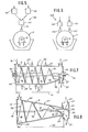
- FIG. 1 shows a calcining device in which a part and transport device 2 is arranged in a stationary vessel 1.
- the part and transport device 2 has a cylindrical helix 3, which is rotatably mounted by means of a shaft 4 in bearings 5 and 6 attached outside the vessel 1 and can be driven by a drive 7.
- the drive 7 is infinitely variable in speed adjustable gear motor.
- the direction of rotation of the helix 3 is indicated in FIG. 2 by an arrow 8.
- the vessel 1 is constructed from a lower half-shell 9 and an upper half-shell 10, which according to FIG. 2 are connected to one another along flanges with screws 11 in a plane that runs through a longitudinal axis 12 of the helix 3.
- the helix 3 is in at least approximately sealing sliding contact with an inner wall 13 of the vessel 1 in the region of the lower half-shell 9. As FIG. 2 particularly shows, the upper half-shell 10 is located at a radial distance from the helix 3.
- a dispersion of calcium sulfate dihydrate and a calcining medium is introduced in the direction of an arrow 14 into a caicinating chamber 15 inside the vessel 1 and stands up to a mirror 16 which runs below a lower edge 17 of the part of the shaft 4 passed through the vessel 1 .
- the gears of the helix 3 located at the bottom divide the dispersion in dispersion sub-quantities 18 of the same volume in the vessel 1, since the pitch of the gears of the helix 3 is constant in this case.
- the partial dispersions 18 are successively transported along a caicination path 19 in Fig. 1 from left to right until finally the finished ⁇ -calcium sulfate hemihydrate flows over an overflow edge 20 of a weir 21 of the vessel 1 and in the direction of an arrow 22 from an outlet 23 of the Vessel 1 is discharged.
- a with End 24 of helix 3, which cooperates with weir 21, is bent towards weir 21 and thus enables complete excavation of the finished oU calcium sulfate hemihydrate from the space adjacent to weir 21.
- the semi-cylindrical heating chambers 25 can be controlled or regulated independently of one another with a heating medium which, according to FIG. 2, is introduced into the heating chambers 25 in the direction of arrows 26 and is left out at the lowest point of each heating chamber 25 in the direction of an arrow 27.
- the part of the inner wall 13 which comes into contact with the partial dispersions 18 has inlet openings 28 distributed over the calcination path 19 for a gaseous heating medium.
- the inlet openings 28 can be controlled or regulated independently of one another with the heating medium.
- the inner wall 13 has, in the uppermost region in the upper half-shell 10, inlet openings 29 which are distributed over the calcination path 19 and which can be acted upon independently of one another in a controlled or regulated manner with calcining medium.
- an aspiration 30 is also provided at the top in the upper half-shell 10, through which water vapor can be sucked out of the calcining space 15.
- the dividing and transport device 2 is designed as a cylindrical helix 32, which is fastened with its outer edge to an inner wall 33 of a drum 34 which surrounds the calcining space 15 and can be driven in rotation, in a liquid-tight manner.
- the helix 32 has a central axial opening 35 through which FIG. 3 leads 36 from the right outside the drum 34 feed lines 36 for a gaseous heating medium and / or calcining medium to predetermined locations of the calcination path 19.
- the drum 34 is rotatably mounted on two pairs of rollers 37, at least one of which can be driven in a manner known per se.
- An outer wall 38 of the drum 34 can be heated by stationary heating chambers 39 which follow one another parallel to the longitudinal axis 12, each heating chamber 39 enclosing the circumference of the drum 34 and a heating medium being fed in at the top and being discharged at the bottom. Furthermore, a stationary inlet connection 40 for the dispersion and a stationary housing 41 are provided, which has the outlet 23 on the one hand and the aspiration 30 on the other hand.
- FIG. 5 shows an input device 42 for the vessel 1, in which a metering device 43 is provided for the calcium sulfate dihydrate and a further metering device 44 is provided for the calcining medium.
- the metering devices 43, 44 are connected to a mixer 45, the outlet of which, according to the arrow 14, feeds the finished dispersion into the vessel 1 continuously.
- FIG. 6 shows a modified embodiment in that the metering devices 43, 44 each have one separate inlet connection 46 and 47 enter the associated dispersion component into the vessel and the mixing for dispersion only takes place in the vessel 1 through the helix 3.
- the part and transport device 2 has a cylindrical starting part 49 and a tapering end part 50 in the form of a helix 48.
- the slope and division of the helix 48 in the direction of the calcination path 19 increases in such a way that there is an at least approximately the same level 16 of the dispersion in the entire calcination space 15.
- the part and transport device 2 is formed as an inside on a tapering, rotating drum 51, also tapered helix 52.
- a tapering, rotating drum 51 also tapered helix 52.
- the calcining medium is prepared by adjusting the concentration of the sulfuric acid and / or the salt solutions with water and preheating to the required temperature.
- the components are metered in, namely the calcium sulfate dihydrate at 25% by weight and the calcining medium at 75% by weight.
- the calcium sulfate dihydrate is dispersed in the calcining medium.
- the dispersion is divided into partial dispersions.
- the partial dispersions are forcibly guided along the calcination path by a helix.
- the water of crystallization begins in the first third of the calcination route.
- the partial dispersions are heated above the boiling point of the water and about the amount of the crystal water which has separated out is evaporated.
- more or less concentrated sulfuric acid and / or saline solution is added, particularly in this zone of the calcination route.
Landscapes
- Chemical & Material Sciences (AREA)
- Organic Chemistry (AREA)
- Ceramic Engineering (AREA)
- Engineering & Computer Science (AREA)
- Inorganic Chemistry (AREA)
- Life Sciences & Earth Sciences (AREA)
- Geology (AREA)
- Materials Engineering (AREA)
- Structural Engineering (AREA)
- Physics & Mathematics (AREA)
- Thermal Sciences (AREA)
- Chemical Kinetics & Catalysis (AREA)
- Compounds Of Alkaline-Earth Elements, Aluminum Or Rare-Earth Metals (AREA)
Abstract
Bei der drucklosen Calcinierung von Calciumsulfat-Dihydrat in Dispersion mit einem Calciniermedium zu α-Calciumsulfat-Halbhydrat wird die Dispersion kontinuierlich hergestellt und in voneinander getrennte Dispersionsteilmengen (18) aufgeteilt, die nacheinander entlang einem Calcinierungsweg (19) transportiert werden. Die Transportgeschwindigkeit kann variiert werden. Längs dem Calcinierungsweg (19) kann die Temperatur der Dispersionsteilmengen (18) verändert werden. Längs dem Calcinierungsweg (19) kann auch die Konzentration des Calciniermediums durch örtliche Zugabe höher konzentrierten Calciniermediums erhöht werden. Es kann auch das Verhältnis von Calciumsulfat-Hydrat zu Calciniermedium durch örtliche Zugaben von Calciniermedium auf einen gewünschten Wert eingestellt werden. Die Dispersionsteilmengen (18) lassen sich durch eine Teil- und Transportvorrichtung (2) herstellen und handhaben, die vorzugsweise eine Wendel (3;32;48;52) aufweist.In the pressure-free calcination of calcium sulfate dihydrate in dispersion with a calcining medium to form α-calcium sulfate hemihydrate, the dispersion is produced continuously and divided into separate dispersion portions (18) which are transported in succession along a calcination path (19). The transport speed can be varied. The temperature of the partial dispersions (18) can be changed along the calcination path (19). Along the calcination path (19), the concentration of the calcining medium can also be increased by locally adding more concentrated calcining medium. The ratio of calcium sulfate hydrate to calcining medium can also be adjusted to a desired value by local additions of calcining medium. The partial dispersions (18) can be produced and handled by a dividing and transport device (2), which preferably has a helix (3; 32; 48; 52).
Description
Die Erfindung betrifft ein Verfahren zu drucklosen Calcinierung von als Nebenprodukt erhaltenem und/oder mineralischem Calciumsulfat-Dihydrat in Dispersion mit einem Calciniermedium, z.B. Schwefelsäure und/oder geeigneten Salzlösungen, in einem beheizten Caicinierungsraum zu α-Calciumsulfat-Halbhydrat.The invention relates to a process for pressure-free calcination of by-product and / or mineral calcium sulfate dihydrate in dispersion with a calcining medium, e.g. Sulfuric acid and / or suitable salt solutions, in a heated caicination room to α-calcium sulfate hemihydrate.
Ein bekanntes Verfahren dieser Art (DE-AS 1 274 488) ist auf die Herstellung eines α -Calciumsulfat-Halbhydrats von ausreichender Reinheit aus einem als Nebenprodukt erhaltenen Calciumsulfat-Dihydrat gerichtet.A known method of this type (DE-AS 1 274 488) is directed to the production of an α-calcium sulfate hemihydrate of sufficient purity from a calcium sulfate dihydrate obtained as a by-product.
Aus der GB-Patentschrift 1 125 989-ist es an sich bekannt, < -Calciumsulfat-Halbhydrat kontinuierlich im Wasserverfahren unter Überdruck herzustellen. Dazu werden wenigstens zwei umlaufende, vom Einlaßende zum Auslaßende hin nach unten geneigte, rohrförmige Druckkammern verwendet. Je zwei benachbarte Druckkammern sind druckdicht durch einen Zwischenspeichertank mit auslaßseitiger Dispersionspumpe miteinander verbunden. Jede Druckkammer weist Einbauten in Form von Rippen und Prallblechen (ridges or baffles) auf, deren Höhe, Winkel oder Anordnung einen Einfluß auf den Durchgang der Dispersion durch die Druckkammer hat. Bei dieser Anlage sind der bauliche und der Betriebsaufwand verhältnismäßig hoch. Man kann auf die Dispersion in der Druckkammer nicht örtlich einwirken. Die Dispersion ist in den Druckkammern nicht unterteilbar, so daß eine Vermischung von Calciumsulfat-Di- und -Halbhydrat nicht zu vermeiden ist.From GB
Der Erfindung liegt die Aufgabe zugrunde, das eingangs erwähnte Verfahren kontinuierlich zu führen und zu verbessern und im Ablauf des Verfahrens Art und Ort der Einwirkung auf die Dispersion zu optimieren.The invention is based on the object of continuously leading and improving the method mentioned at the outset and of optimizing the type and location of the action on the dispersion in the course of the method.
Diese Aufgabe ist durch die im Kennzeichnungsteil des Anspruchs 1 angegebenen Schritte gelöst. Es kann z.B. als Nebenprodukt erhaltener Rauchgasentschwefelungsgips oder Chemiegips verarbeitet werden. Die Unterteilung in Dispersionsteilmengen gestattet eine optimale Reaktion der und Einflußnahme auf die Dispersionsteilmengen entlang dem Calcinierungsweg.This object is achieved by the steps specified in the characterizing part of
Die Merkmale des Anspruchs 2 gestatten eine einfache Einflußnahme auf die Calcinierungsdauer. Vorzugsweise ist die Transportgeschwindigkeit und damit die Aufenthaltsdauer der Dispersion in dem Calcinierungsraum stufenlos einstellbar.The features of
Die Merkmale des Anspruchs 3 ermöglichen eine Differenzierung der Calcinierungsdauer der Dispersionsteilmengen.The features of claim 3 allow a differentiation of the calcination time of the dispersion subsets.
Gemäß Anspruch 4 läßt sich eine beliebig feinfühlige Temperaturführung der Dispersionsteilmengen erreichen.According to
Gemäß Anspruch 5 kann gegengesteuert werden, wenn durch Ausscheidung von Kristallwasser längs dem Calcinierungsv;eg eine zu hohe Verdünnung des Calciniermediums eintritt.According to
Die Merkmale des Anspruchs 6 gestatten es, die Viskosität der Dispersionsteilmengen stets optimal zu halten.The features of claim 6 allow the viscosity of the partial dispersions to always be kept optimal.
Das Rühren gemäß Anspruch 7 beschleunigt und verbessert den Ablauf der Reaktion.The stirring according to
Insgesamt kann mittels des erfindungsgemäßen Verfahrens die Prozeßführung dem idealen Calcinierungsverlauf optimal angepaßt werden. Der kontinuierliche Verfahrensablauf erleichtert die Prozeßautomatisierung und ermöglicht eine Vergleichmäßigung der Qualität und gesteigerte Wirtschaftlichkeit der Calcinierung.Overall, the process control can be optimally adapted to the ideal course of calcination by means of the method according to the invention. The continuous process sequence facilitates process automation and enables the quality of the calcination to be evened out and the cost-effectiveness to be increased.
Die zugrundeliegende Aufgabe ist auch durch die erfindungsgemäße Vorrichtung gemäß Anspruch 8 gelöst.The underlying object is also achieved by the device according to the invention.
Die Wendel gemäß Anspruch 9 erweist sich als besonders einfache Teil- und Transportvorrichtung von hoher Funktionssicherheit. Auf einfache Weise ist eine vielfältige Einflußnahme auf die Dispersionsteilmengen auf dem Calcinierungsweg ermöglicht. Vorzugsweise ist die Welle "trokken" gelagert, wobei der Spiegel der Dispersion unter einer Lagerunterkante steht.The helix according to
Die Ausbildung der Vorrichtung gemäß Anspruch 10 ist besonders einfach und wartungsfrei und mindert aufgrund der nur örtlichen Gleitberührung den Verschleiß.The design of the device according to
Mit den Heizkammern gemäß Anspruch 11 läßt sich eine beliebig feinfühlige Temperaturführung des Prozesses erreichen. Das Heizmedium kann flüssig, aber auch gasförmig, z.B. Rauchgas oder Abdampf, sein. Im Fall einer Automatisierung der Beaufschlagung der Heizkammern mit Heizmedium ist zweckmäßigerweise jeder Heizkammer ein Temperaturfühler zugeordnet, der mit einer an sich bekannten Steuer-oder Regelschaltung verknüpft ist und für die gewünschte differenzierte Beaufschlagung mit Heizmedium sorgt.With the heating chambers according to
Mit ähnlichem Ziel kann gemäß Anspruch 12 durch die Einlaßöffnungen gasförmiges Heizmedium unmittelbar in die betreffenden Dispersionsteilmengen eingebracht werden.With a similar goal, gaseous heating medium can be introduced directly into the relevant partial dispersions through the inlet openings.
Die Merkmale des Anspruchs 13 gestatten die Aufrechterhaltung einer gewünschten Viskosität der Dispersion und/oder einer gewünschten Konzentration des Calciniermediums. Vorzugsweise geschieht die Beaufschlagung der Einlaßöffnungen dosiert.The features of
Das Wehr gemäß Anspruch 14 erhält auch bei gelegentlichem Stillstand der Teil- und Transportvorrichtung einen gleichmäßigen Spiegel der Dispersion in dem Calcinierungsraum aufrecht.The weir according to
Das gemäß Anspruch 15 umgebogene Wendelende räumt das fertige oc -Calciumsulfat-Halbhydrat vollständig aus dem Bereich des Wehrs aus.The bent end according to
Die Trommel und die Wendel gemäß Anspruch 16 bieten einen absolut flüssig keitsdichten Abschluß der einzelnen Dispersionsteilmengen gegeneinander. Die Trommel kann z.B. auf Rollenpaaren gelagert und durch diese drehend antreibbar sein.The drum and the helix according to
Anspruch 17 ermöglicht die gewünschten Zugaben ohne Durchbrechung des Trommelmantels.Claim 17 enables the desired additions without breaking the drum jacket.
Anspruch 18 ermöglicht auch bei der Trommel eine zonenweise differenzierte Beheizung der Dispersionsteilmengen.
Die Eingabeeinrichtung kann für das Calcuimsulfat-Dihydrat und das Calciniermedium je eine Dosiervorrichtung und einen den Dosiervorrichtungen nachgeschalteten Mischer aufweisen, dessen Ausgang in den Calcinierungsraum mündet. Das begünstigt den Prozeßablauf insofern, als schon fertige Dispersion in den Calcinierungsraum eingegeben werden kann. Als Dosiervorrichtung kann z.B. eine Zellenradschleuse oder eine Dosierpumpe verwendet werden.The input device can each have a metering device and a mixer connected downstream of the metering devices for the calcium sulfate dihydrate and the calcining medium, the outlet of which opens into the calcining room. This favors the process in that already finished dispersion can be fed into the calcining room. As a dosing device e.g. a rotary valve or a metering pump can be used.
Die Eingabeeinrichtung kann auch für das Calciumsulfat-Dihydrat und das Calciniermedium je eine Dosiervorrichtung aufweisen, deren Ausgänge jeweils in den Calcinierungsraum münden. Das bringt Vorteile insofern, als auf einen gesonderten Mischer verzichtet und die Mischung im Calcinierungsraum selbst vorgenommen werden kann.The input device can also each have a metering device for the calcium sulfate dihydrate and the calcining medium, the outputs of which each open into the calcining room. This has advantages in that a separate mixer is dispensed with and the mixing can be carried out in the calcining room itself.
Die Rührelemente gemäß Anspruch 19 werden vorzugsweise entlang dem Calcinierungsweg dort angebracht, wo bereits überwiegend oc -Calciumsulfat-Halbhydrat vorliegt, das kaum noch Neigung zu "scaling und clogging" zeigt. So können unerwünschte Aufbauten auf den Rührelementen und Brückenbildungen an der Wendel vermieden werden.The stirring elements according to
Die Rührelemente gemäß Anspruch 20 sind konstruktiv besonders einfach und dennoch sehr wirksam.The stirring elements according to
Die Ausbildung der Teil- und Transportvorrichtung gemäß Anspruch 21 ist wegen ihrer konstruktiven und baulichen Einfachheit bevorzugt.The design of the part and transport device according to
Die Verjüngungen gemäß den Ansprüchen 22 und 23 dienen der zunehmenden Beschleunigung der Dispersionsteilmengen in Richtung des CalcinierungswegsoThe tapers according to
Die Maßnahmen gemäß Anspruch 24 bieten betriebliche Vorteile.The measures according to
Die Erfindung wird nachfolgend anhand der in den Zeichnungen dargestellten Ausführungsbeispiele näher erläutert. Es zeigen:
- Fig. 1 einen Längsschnitt durch eine Calciniervorrichtung mit einer in einem Gefäß drehbar gelagerten Wendel,
- Fig. 2 die Schnittansicht nach Linie 2-2 in Fig. 1,
- Fig. 3 einen Längsschnitt durch eine andere Calciniervorrichtung mit einer in einer umlaufenden Trommel befestigten Wendel,
- Fig. 4 die Schnittansicht nach Linie 4-4 in Fig. 3,
- Fig. 5 eine schematische Darstellung einer Eingabeeinrichtung,
- Fig. 6 eine schematische Darstellung einer anderen Eingabeeinrichtung,
- Fig. 7 einen Längsschnitt durch eine weitere Calciniervorrichtung mit sich am Auslaßende verjüngender Wendel und
- Fig. 8 einen Längsschnitt durch eine weitere Calciniervorrichtung mit sich über die ganze Länge zum Auslaßende hin verjüngender Wendel.
- 1 shows a longitudinal section through a calcining device with a helix rotatably mounted in a vessel,
- 2 shows the sectional view along line 2-2 in FIG. 1,
- 3 shows a longitudinal section through another calcining device with a helix fastened in a rotating drum,
- 4 shows the sectional view along line 4-4 in FIG. 3,
- 5 shows a schematic illustration of an input device,
- 6 shows a schematic illustration of another input device,
- 7 shows a longitudinal section through a further calcining device with a helix tapering at the outlet end
- 8 shows a longitudinal section through a further calcining device with a helix tapering over the entire length towards the outlet end.
Fig. 1 zeigt eine Calciniervorrichtung, bei der in einem stationären Gefäß 1 eine Teil- und Transportvorrichtung 2 angeordnet ist. Die Teil- und Transportvorrichtung 2 weist eine zylindrische Wendel 3 auf, die mittels einer Welle 4 in außerhalb des Gefäßes 1 angebrachten Lagern 5 und 6 drehbar gelagert und durch einen Antrieb 7 antreibbar ist. Der Antrieb 7 ist als in der Drehzahl stufenlos einstellbarer Getriebemotor ausgebildet. Die Umlaufrichtung der Wendel 3 ist in Fig. 2 durch einen Pfeil 8 angedeutet.1 shows a calcining device in which a part and
Das Gefäß 1 ist aus einer unteren Halbschale 9 und einer oberen Halbschale 10 aufgebaut, die gemäß Fig. 2 längs Flanschen mit Schrauben 11 in einer Ebene miteinander verbunden sind, die durch eine Längsachse 12 der Wendel 3 verläuft.The
Die Wendel 3 steht in zumindest annähernd dichtender Gleitberührung mit einer Innenwand 13 des Gefäßes 1 im Bereich der unteren Halbschale 9. Wie besonders Fig. 2 zeigt, befindet sich dagegen die obere Halbschale 10 in einem radialen Abstand von der Wendel 3.The helix 3 is in at least approximately sealing sliding contact with an
Eine Dispersion aus Calciumsulfat-Dihydrat und einem Calciniermedium wird in Richtung eines Pfeiles 14 in einen Caicinierungsraum 15 im Inneren des Gefäßes 1 eingebracht und steht darin bis zu einem Spiegel 16, der unterhalb einer Unterkante 17 des durch das Gefäß 1 hindurchgeführten Teiles der Welle 4 verläuft. So ist auch ohne flüssigkeitsdichte Abdichtung der Welle 4 gegenüber dem Gefäß 1 gewährleistet, daß Dispersion nicht aus dem Gefäß 1 austreten kann.A dispersion of calcium sulfate dihydrate and a calcining medium is introduced in the direction of an
Die jeweils unten liegenden Gänge der Wendel 3 unterteilen die in dem Gefäß 1 stehende Dispersion in-Dispersionsteilmengen 18 von gleich großem Volumen, da die Steigung der Gänge der Wendel 3 in diesem Fall konstant ist. Die Dispersionsteilmengen 18 werden nacheinander entlang einem Caicinierungsweg 19 in Fig. 1 von links nach rechts transportiert, bis schließlich das fertige α-Calciumsulfat-Halbhydrat über eine Überlaufkante 20 eines Wehrs 21 des Gefäßes 1 strömt und in Richtung eines Pfeiles 22 aus einem Auslaß 23 des Gefäßes 1 ausgetragen wird. Ein mit dem Wehr 21 zusammenwirkendes Ende 24 der Wendel 3 ist zum Wehr 21 hin umgebogen und ermöglicht damit einen vollständigen Aushub des fertigen oU-Calciumsulfat-Halbhydrats aus dem an das Wehr 21 angrenzenden Raum.The gears of the helix 3 located at the bottom divide the dispersion in
Aus den Fig. 1 und 2 ist ersichtlich, daß die durch die untere Halbschale 9 definierte Innenwand 13 des Gefäßes 1 durch parallel zu der Welle 4 aufeinander folgende Heizkammern 25 beheizbar ist.1 and 2 that the
Die halbzylindrischen Heizkammern 25 können unabhängig voneinander gesteuert oder geregelt mit einem Heizmedium beaufschlagt werden, das gemäß Fig. 2 in Richtung von Pfeilen 26 in die Heizkammern 25 eingeleitet und am tiefsten Punkt jeder Heizkammer 25 in Richtung eines Pfeiles 27 ausgelassen wird.The
Der mit den Dispersionsteilmengen 18 in Berührung tretende Teil der Innenwand 13 weist über den Calcinierungsweg 19 verteilte Einlaßöffnungen 28 für ein gasförmiges Heizmedium auf. Die Einlaßöffnungen 28 können unabhängig voneinander gesteuert oder geregelt mit dem Heizmedium beaufschlagt werden.The part of the
Die Innenwand 13 weist im obersten Bereich in der oberen Halbschale 10 über den Calcinierungsweg 19 verteilte Einlaßöffnungen 29 auf, die unabhängig voneinander gesteuert oder geregelt mit Calciniermedium beaufschlagbar sind.The
Am Auslaßende des Gefäßes 1 ist ferner oben in der oberen Halbschale 10 eine Aspiration 30 vorgesehen, durch die Wasserdampf aus dem Calcinierungsraum 15 abgesaugt werden kann.At the outlet end of the
Auf dem letzten Teil des Calcinierungswegs 19 sind zwischen benachbarten Wendelgängen Rührstege 31 befestigt. Bei dem in den Fig. 3 und 4 dargestellten Ausführungsbeispiel sind gleiche Teile wie in den Fig. 1 und 2 mit gleichen Bezugszahlen versehen. Die Teil- und Transportvorrichtung 2 ist in diesem Fall als zylindrische Wendel 32 ausgebildet, die mit ihrer Außenkante an einer Innenwand 33 einer den Calcinierungsraum 15 umschließenden, drehend antreibbaren Trommel 34 flüssigkeitsdicht befestigt ist. Die Wendel 32 weist eine mittige axiale Durchbrechung 35 auf, durch die sich Fig. 3 von rechts außerhalb der Trommel 34 Zuleitungen 36 für ein gasförmiges Heizmedium und/oder Calciniermedium an vorbestimmte Stellen des Calcinierungswegs 19 erstrecken.On the last part of the
Die Trommel 34 ist auf zwei Paaren von Rollen 37 drehbar gelagert, von denen wenigstens eine in an sich bekannter Weise antreibbar ist.The
Eine Außenwand 38 der Trommel 34 ist durch parallel zu der Längsachse 12 aufeinanderfolgende, stationäre Heizkammern 39 beheizbar, wobei jede Heizkammer 39 den Umfang der Trommel 34 umschließt und ein Heizmedium oben zugeführt und unten abgeführt wird. Ferner ist ein stationärer Einlaßstutzen 40 für die Dispersion und ein stationäres Gehäuse 41 vorgesehen, das einerseits den Auslaß 23 und andererseits die Aspiration 30 aufweist.An
Fig. 5 zeigt eine Eingabeeinrichtung 42 für das Gefäß 1, bei der für das Calciumsulfat-Dihydrat eine Dosiervorrichtung 43 und für das Calciniermedium eine weitere Dosiervorrichtung 44 vorgesehen sind. Die Dosiervorrichtungen 43,44 sind mit einem Mischer 45 verbunden, dessen Ausgang gemäß dem Pfeil 14 die fertige Dispersion in das Gefäß 1 kontinuierlich einspeist.5 shows an
Fig. 6 stellt eine abgewandelte Ausführungsform insofern dar, als die Dosiervorrichtungen 43,44 jeweils über einen gesonderten Einlaßstutzen 46 und 47 die zugehörige Dispersionskomponente in das Gefäß eingeben und die Vermischung zur Dispersion erst in dem Gefäß 1 durch die Wendel 3 stattfindet.FIG. 6 shows a modified embodiment in that the
In den Fig. 7 und 8 sind wiederum gleiche Teile mit gleichen Bezugszahlen versehen.7 and 8, the same parts are again provided with the same reference numbers.
In Fig. 7 weist die Teil- und Transportvorrichtung 2 in Gestalt einer Wendel 48 einen zylindrischen Anfangsteil 49 und einen sich verjüngenden Endteil 50 auf. In dem Endteil 50 nimmt die Steigung und Teilung der Wendel 48 in Richtung des Calcinierungswegs 19 derart zu, daß in dem gesamten Calcinierungsraum 15 ein zumindest annähernd gleich hoher Spiegel 16 der Dispersion besteht.In FIG. 7, the part and
In Fig. 8 ist die Teil- und Transportvorrichtung 2 als Innen an einer sich verjüngenden, umlaufenden Trommel 51 befestigte, sich ebenfalls verjüngende Wendel 52 ausgebildet. Auch hier ist durch Anpassung von Steigung und Teilung der Wendel 52 an die zunehmende Verjüngung sichergestellt, daß sich ein gleich hoher Spiegel 16 der Dispersion in dem gesamten Calcinierungsraum 15 hält.In Fig. 8, the part and
Zur weiteren Erläuterung der Erfindung dient das nachfolgendeThe following serves to further explain the invention
Das Calciniermedium wird vorbereitet, indem die Konzentration der Schwefelsäure und/oder der Salzlösungen mit Wasser eingestellt und auf die benötigte Temperatur vorgeheizt wird.The calcining medium is prepared by adjusting the concentration of the sulfuric acid and / or the salt solutions with water and preheating to the required temperature.
Die Komponenten werden dosiert, und zwar das Calciumsulfat-Dihydrat mit 25 Gew.-% und das Calciniermedium mit 75 Gew.-%.The components are metered in, namely the calcium sulfate dihydrate at 25% by weight and the calcining medium at 75% by weight.
Das Calciumsulfat-Dihydrat wird im Calciniermedium dispergiert.The calcium sulfate dihydrate is dispersed in the calcining medium.
Im Einlaufbereich der Calciniervorrichtung erfolgt die Unterteilung der Dispersion in Dispersionsteilmengen.In the inlet area of the calciner, the dispersion is divided into partial dispersions.
In der Calciniervorrichtung werden die Dispersionsteilmengen entlang dem Calcinierungsweg durch eine Wendel zwangsweise geführt.In the calciner, the partial dispersions are forcibly guided along the calcination path by a helix.
Im ersten Drittel des Calcinierungswegs beginnt die Kristallwasserausscheidung.The water of crystallization begins in the first third of the calcination route.
Im zweiten Drittel des Calcinierungswegs werden die Dispersionsteilmengen über den Siedepunkt des Wassers aufgeheizt und etwa die Menge des ausgeschiedenen Kristallwassers verdampft. Zur Konzentrationsregulierung des Caciniermediums wird insbesondere in dieser Zone des Calcinierungswegs mehr oder weniger konzentrierte Schwefelsäure und/oder Salzlösung hinzugegeben.In the second third of the calcination route, the partial dispersions are heated above the boiling point of the water and about the amount of the crystal water which has separated out is evaporated. To regulate the concentration of the calcination medium, more or less concentrated sulfuric acid and / or saline solution is added, particularly in this zone of the calcination route.
Im letzten Drittel des Calcinierungswegs wird die Calcinierung vervollständigt, unter zusätzlichem Rühren der Dispersionsteilmengen mittels Rührstegen zwischen den Wendelgängen.In the last third of the calcination route, the calcination is completed, with additional stirring of the partial dispersions by means of stirrers between the spiral passages.
Claims (24)
Applications Claiming Priority (2)
| Application Number | Priority Date | Filing Date | Title |
|---|---|---|---|
| DE19813139384 DE3139384A1 (en) | 1981-10-03 | 1981-10-03 | METHOD AND DEVICE FOR THE PRESSURE-FREE PRODUCTION OF (ALPHA) CALCIUM SULFATE HALBHYDRATE |
| DE3139384 | 1981-10-03 |
Publications (2)
| Publication Number | Publication Date |
|---|---|
| EP0077475A2 true EP0077475A2 (en) | 1983-04-27 |
| EP0077475A3 EP0077475A3 (en) | 1985-08-21 |
Family
ID=6143322
Family Applications (1)
| Application Number | Title | Priority Date | Filing Date |
|---|---|---|---|
| EP82108897A Withdrawn EP0077475A3 (en) | 1981-10-03 | 1982-09-25 | Process and apparatus for the pressureless production of alpha-calcium sulphate-hemihydrate |
Country Status (3)
| Country | Link |
|---|---|
| EP (1) | EP0077475A3 (en) |
| BE (1) | BE892194A (en) |
| DE (1) | DE3139384A1 (en) |
Cited By (1)
| Publication number | Priority date | Publication date | Assignee | Title |
|---|---|---|---|---|
| FR2700327A1 (en) * | 1993-01-14 | 1994-07-13 | Gupsos | Control of oven for dehydration of gypsum |
Family Cites Families (11)
| Publication number | Priority date | Publication date | Assignee | Title |
|---|---|---|---|---|
| DE1157128B (en) * | 1962-05-25 | 1963-11-07 | Giulini Ges Mit Beschraenkter | Process for the production of ª ‡ calcium sulfate hemihydrate from synthetic calcium sulfate dihydrate |
| GB1101771A (en) * | 1963-08-14 | 1968-01-31 | Bpb Industries Ltd | Improvements relating to the production of gypsum plaster |
| GB1051849A (en) * | 1963-12-03 | |||
| DE1238374B (en) * | 1965-04-24 | 1967-04-06 | Giulini Ges Mit Beschraenkter | Process for the production of alpha calcium sulfate hemihydrate |
| AU6714265A (en) * | 1965-11-26 | 1968-05-16 | Continuous production of alpha plaster | |
| DE1592080A1 (en) * | 1966-10-27 | 1970-09-10 | Central Glass Co Ltd | Manufacturing process for gypsum of high purity |
| DE1592121C3 (en) * | 1967-08-16 | 1975-08-14 | Gebrueder Giulini Gmbh, 6700 Ludwigshafen | Process for the continuous production of alpha calcium sulfate hemihydrate |
| AU423448B2 (en) * | 1968-03-28 | 1972-04-21 | Monzino Riotinto Of Australia Limited | Production of alpha plaster |
| DE1940007B2 (en) * | 1969-08-06 | 1973-06-07 | Rheinstahl Ag, 4300 Essen | METHOD OF BURNING PLASTER IN A FLOW OF HEATING GAS |
| DE2102766A1 (en) * | 1971-01-21 | 1972-08-03 | Zimmermann & Vonhof Kessel-, Behälter- und Apparatebau KG, 5674 Bergisch Neukirchen | Method and device for drying powdery or flour-like bulk materials |
| GB1585584A (en) * | 1976-06-08 | 1981-03-04 | Kobe Steel Ltd | Process and apparatus for heating solid materials containing volatile matter |
-
1981
- 1981-10-03 DE DE19813139384 patent/DE3139384A1/en not_active Withdrawn
-
1982
- 1982-02-18 BE BE0/207351A patent/BE892194A/en not_active IP Right Cessation
- 1982-09-25 EP EP82108897A patent/EP0077475A3/en not_active Withdrawn
Cited By (1)
| Publication number | Priority date | Publication date | Assignee | Title |
|---|---|---|---|---|
| FR2700327A1 (en) * | 1993-01-14 | 1994-07-13 | Gupsos | Control of oven for dehydration of gypsum |
Also Published As
| Publication number | Publication date |
|---|---|
| BE892194A (en) | 1982-06-16 |
| EP0077475A3 (en) | 1985-08-21 |
| DE3139384A1 (en) | 1983-04-21 |
Similar Documents
| Publication | Publication Date | Title |
|---|---|---|
| DE69129017T2 (en) | BLEACHING OF CELLULAR AND REACTOR | |
| DE69304281T2 (en) | DEVICE FOR SEPARATING SOLIDS AND LIQUIDS | |
| DE3301053A1 (en) | DEVICE FOR SEPARATING LIQUID FROM A MUDDY Porridge OR SOLID LIQUID | |
| DE3224204A1 (en) | CENTRIFUGE | |
| DE2342891C3 (en) | Vacuum evaporator for continuous evaporation of sugar solutions | |
| EP1622706B1 (en) | Mixing device, and mixing method using that device | |
| DE2830491C2 (en) | ||
| DE2343323C2 (en) | Mixing tank for the continuous addition and mixing of flocculants to sludge, especially sewage sludge | |
| EP0448766A2 (en) | Mixer-dryer, or apparatus for working or processing liquid, pasty, moist and dry products | |
| EP4475657A1 (en) | Seed on-demand system | |
| EP0077475A2 (en) | Process and apparatus for the pressureless production of alpha-calcium sulphate-hemihydrate | |
| DE2644925C3 (en) | Device for handling liquids, in particular waste water | |
| DE3124738A1 (en) | TRANSPORTABLE DEVICE FOR PROCESSING USED EMULSIONS, SOLUTIONS AND INDUSTRIAL WASTEWATERS OR THE LIKE | |
| DE4127873C2 (en) | Kneading device for a mass to be kneaded | |
| DE3918527C2 (en) | ||
| DE1546228A1 (en) | Device for mixing bleach into cellulose pulp | |
| DE3529983C2 (en) | ||
| DE2434422A1 (en) | INCINERATOR FOR AN INCINERATOR FOR SOLID WASTE | |
| DE2921063A1 (en) | Scroll filter press for sepg. water from organic fibres - has roller rotating with scroll against cylindrical filter wall to achieve compression | |
| DE3112994C2 (en) | Autoclave for processing cocoa mass | |
| DE3018729C2 (en) | Device for simultaneous and continuous feeding of a powdery solid and a liquid into a treatment machine | |
| DE2844038C2 (en) | Device for the intimate mixing of two material components, at least one of which is liquid | |
| DE1945615A1 (en) | Process and system for liquefying and stirring refined chocolate | |
| DE2106959C3 (en) | Device for treating waste water or the like | |
| CH657600A5 (en) | Transfer conveyor. |
Legal Events
| Date | Code | Title | Description |
|---|---|---|---|
| PUAI | Public reference made under article 153(3) epc to a published international application that has entered the european phase |
Free format text: ORIGINAL CODE: 0009012 |
|
| AK | Designated contracting states |
Designated state(s): AT CH DE FR GB IT LI LU NL SE |
|
| PUAL | Search report despatched |
Free format text: ORIGINAL CODE: 0009013 |
|
| AK | Designated contracting states |
Designated state(s): AT CH DE FR GB IT LI LU NL SE |
|
| RAP1 | Party data changed (applicant data changed or rights of an application transferred) |
Owner name: QUANTE, HEINRICH |
|
| 17P | Request for examination filed |
Effective date: 19860201 |
|
| STAA | Information on the status of an ep patent application or granted ep patent |
Free format text: STATUS: THE APPLICATION IS DEEMED TO BE WITHDRAWN |
|
| 18D | Application deemed to be withdrawn |
Effective date: 19870401 |
|
| RIN1 | Information on inventor provided before grant (corrected) |
Inventor name: SCHMIDT, HANS |