EP0077543B1 - Druckregler - Google Patents
Druckregler Download PDFInfo
- Publication number
- EP0077543B1 EP0077543B1 EP82109554A EP82109554A EP0077543B1 EP 0077543 B1 EP0077543 B1 EP 0077543B1 EP 82109554 A EP82109554 A EP 82109554A EP 82109554 A EP82109554 A EP 82109554A EP 0077543 B1 EP0077543 B1 EP 0077543B1
- Authority
- EP
- European Patent Office
- Prior art keywords
- pressure
- bellow
- sealing disc
- atmospheric pressure
- pressure regulator
- Prior art date
- Legal status (The legal status is an assumption and is not a legal conclusion. Google has not performed a legal analysis and makes no representation as to the accuracy of the status listed.)
- Expired
Links
- 238000007789 sealing Methods 0.000 claims description 35
- 230000003247 decreasing effect Effects 0.000 claims description 3
- 239000012080 ambient air Substances 0.000 claims description 2
- 238000004891 communication Methods 0.000 claims description 2
- 239000002699 waste material Substances 0.000 description 4
- 238000002485 combustion reaction Methods 0.000 description 2
- 230000006835 compression Effects 0.000 description 2
- 238000007906 compression Methods 0.000 description 2
- 238000010276 construction Methods 0.000 description 2
- 238000010586 diagram Methods 0.000 description 2
- 230000000694 effects Effects 0.000 description 2
- 230000001419 dependent effect Effects 0.000 description 1
- 230000002040 relaxant effect Effects 0.000 description 1
- 239000002912 waste gas Substances 0.000 description 1
Images


Classifications
-
- F—MECHANICAL ENGINEERING; LIGHTING; HEATING; WEAPONS; BLASTING
- F02—COMBUSTION ENGINES; HOT-GAS OR COMBUSTION-PRODUCT ENGINE PLANTS
- F02B—INTERNAL-COMBUSTION PISTON ENGINES; COMBUSTION ENGINES IN GENERAL
- F02B37/00—Engines characterised by provision of pumps driven at least for part of the time by exhaust
- F02B37/12—Control of the pumps
- F02B37/18—Control of the pumps by bypassing exhaust from the inlet to the outlet of turbine or to the atmosphere
- F02B37/183—Arrangements of bypass valves or actuators therefor
-
- F—MECHANICAL ENGINEERING; LIGHTING; HEATING; WEAPONS; BLASTING
- F02—COMBUSTION ENGINES; HOT-GAS OR COMBUSTION-PRODUCT ENGINE PLANTS
- F02B—INTERNAL-COMBUSTION PISTON ENGINES; COMBUSTION ENGINES IN GENERAL
- F02B37/00—Engines characterised by provision of pumps driven at least for part of the time by exhaust
- F02B37/12—Control of the pumps
- F02B37/18—Control of the pumps by bypassing exhaust from the inlet to the outlet of turbine or to the atmosphere
-
- F—MECHANICAL ENGINEERING; LIGHTING; HEATING; WEAPONS; BLASTING
- F02—COMBUSTION ENGINES; HOT-GAS OR COMBUSTION-PRODUCT ENGINE PLANTS
- F02B—INTERNAL-COMBUSTION PISTON ENGINES; COMBUSTION ENGINES IN GENERAL
- F02B37/00—Engines characterised by provision of pumps driven at least for part of the time by exhaust
- F02B37/12—Control of the pumps
- F02B37/18—Control of the pumps by bypassing exhaust from the inlet to the outlet of turbine or to the atmosphere
- F02B37/183—Arrangements of bypass valves or actuators therefor
- F02B37/186—Arrangements of actuators or linkage for bypass valves
-
- G—PHYSICS
- G05—CONTROLLING; REGULATING
- G05D—SYSTEMS FOR CONTROLLING OR REGULATING NON-ELECTRIC VARIABLES
- G05D16/00—Control of fluid pressure
- G05D16/04—Control of fluid pressure without auxiliary power
- G05D16/06—Control of fluid pressure without auxiliary power the sensing element being a flexible membrane, yielding to pressure, e.g. diaphragm, bellows, capsule
- G05D16/063—Control of fluid pressure without auxiliary power the sensing element being a flexible membrane, yielding to pressure, e.g. diaphragm, bellows, capsule the sensing element being a membrane
- G05D16/0638—Control of fluid pressure without auxiliary power the sensing element being a flexible membrane, yielding to pressure, e.g. diaphragm, bellows, capsule the sensing element being a membrane characterised by the form of the obturator
- G05D16/0641—Control of fluid pressure without auxiliary power the sensing element being a flexible membrane, yielding to pressure, e.g. diaphragm, bellows, capsule the sensing element being a membrane characterised by the form of the obturator the obturator is a membrane
-
- G—PHYSICS
- G05—CONTROLLING; REGULATING
- G05D—SYSTEMS FOR CONTROLLING OR REGULATING NON-ELECTRIC VARIABLES
- G05D16/00—Control of fluid pressure
- G05D16/04—Control of fluid pressure without auxiliary power
- G05D16/06—Control of fluid pressure without auxiliary power the sensing element being a flexible membrane, yielding to pressure, e.g. diaphragm, bellows, capsule
- G05D16/063—Control of fluid pressure without auxiliary power the sensing element being a flexible membrane, yielding to pressure, e.g. diaphragm, bellows, capsule the sensing element being a membrane
- G05D16/0644—Control of fluid pressure without auxiliary power the sensing element being a flexible membrane, yielding to pressure, e.g. diaphragm, bellows, capsule the sensing element being a membrane the membrane acting directly on the obturator
- G05D16/0655—Control of fluid pressure without auxiliary power the sensing element being a flexible membrane, yielding to pressure, e.g. diaphragm, bellows, capsule the sensing element being a membrane the membrane acting directly on the obturator using one spring-loaded membrane
- G05D16/0661—Control of fluid pressure without auxiliary power the sensing element being a flexible membrane, yielding to pressure, e.g. diaphragm, bellows, capsule the sensing element being a membrane the membrane acting directly on the obturator using one spring-loaded membrane characterised by the loading mechanisms of the membrane
-
- Y—GENERAL TAGGING OF NEW TECHNOLOGICAL DEVELOPMENTS; GENERAL TAGGING OF CROSS-SECTIONAL TECHNOLOGIES SPANNING OVER SEVERAL SECTIONS OF THE IPC; TECHNICAL SUBJECTS COVERED BY FORMER USPC CROSS-REFERENCE ART COLLECTIONS [XRACs] AND DIGESTS
- Y02—TECHNOLOGIES OR APPLICATIONS FOR MITIGATION OR ADAPTATION AGAINST CLIMATE CHANGE
- Y02T—CLIMATE CHANGE MITIGATION TECHNOLOGIES RELATED TO TRANSPORTATION
- Y02T10/00—Road transport of goods or passengers
- Y02T10/10—Internal combustion engine [ICE] based vehicles
- Y02T10/12—Improving ICE efficiencies
-
- Y—GENERAL TAGGING OF NEW TECHNOLOGICAL DEVELOPMENTS; GENERAL TAGGING OF CROSS-SECTIONAL TECHNOLOGIES SPANNING OVER SEVERAL SECTIONS OF THE IPC; TECHNICAL SUBJECTS COVERED BY FORMER USPC CROSS-REFERENCE ART COLLECTIONS [XRACs] AND DIGESTS
- Y10—TECHNICAL SUBJECTS COVERED BY FORMER USPC
- Y10T—TECHNICAL SUBJECTS COVERED BY FORMER US CLASSIFICATION
- Y10T137/00—Fluid handling
- Y10T137/1842—Ambient condition change responsive
- Y10T137/1939—Atmospheric
- Y10T137/2012—Pressure
-
- Y—GENERAL TAGGING OF NEW TECHNOLOGICAL DEVELOPMENTS; GENERAL TAGGING OF CROSS-SECTIONAL TECHNOLOGIES SPANNING OVER SEVERAL SECTIONS OF THE IPC; TECHNICAL SUBJECTS COVERED BY FORMER USPC CROSS-REFERENCE ART COLLECTIONS [XRACs] AND DIGESTS
- Y10—TECHNICAL SUBJECTS COVERED BY FORMER USPC
- Y10T—TECHNICAL SUBJECTS COVERED BY FORMER US CLASSIFICATION
- Y10T137/00—Fluid handling
- Y10T137/2496—Self-proportioning or correlating systems
- Y10T137/2559—Self-controlled branched flow systems
- Y10T137/2574—Bypass or relief controlled by main line fluid condition
- Y10T137/2605—Pressure responsive
- Y10T137/2607—With pressure reducing inlet valve
-
- Y—GENERAL TAGGING OF NEW TECHNOLOGICAL DEVELOPMENTS; GENERAL TAGGING OF CROSS-SECTIONAL TECHNOLOGIES SPANNING OVER SEVERAL SECTIONS OF THE IPC; TECHNICAL SUBJECTS COVERED BY FORMER USPC CROSS-REFERENCE ART COLLECTIONS [XRACs] AND DIGESTS
- Y10—TECHNICAL SUBJECTS COVERED BY FORMER USPC
- Y10T—TECHNICAL SUBJECTS COVERED BY FORMER US CLASSIFICATION
- Y10T137/00—Fluid handling
- Y10T137/2496—Self-proportioning or correlating systems
- Y10T137/2559—Self-controlled branched flow systems
- Y10T137/2574—Bypass or relief controlled by main line fluid condition
- Y10T137/2605—Pressure responsive
- Y10T137/2607—With pressure reducing inlet valve
- Y10T137/261—Relief port through common sensing means
Definitions
- the invention relates to a pressure regulator comprising a high-pressure chamber and a second pressure chamber, between which a diaphragm is disposed as well as a co-acting sealing disc movable in relation thereto, said diaphragm or sealing disc, respectively, selectively closing both a port to atmospheric pressure and a through port between high-pressure chamber and second pressure chamber and said sealing disc being pressed towards said diaphragm under the action of at least one spring, the pressure regulator having bellow means responding to changes in the atmospheric pressure for increasing or decreasing, respectively, the bias of said spring upon sinking or increasing atmospheric pressure.
- a pressure regulator is e.g. known from EP-A-0 035 691.
- the bellow means is arranged to increase controlled high-pressure upon sinking atmospheric pressure.
- US-A-2 376 199 discloses an aircraft supercharger system including a bellows means responding to atmospheric pressure of additionally controlling the position of a waste- gate valve.
- US-A-3 611 911 discloses a turbocharger control unit of relatively complicated construction including a bellow means responding to atmospheric pressure of influencing a controlled pressure.
- a waste gate valve In the control of turbo chargers for internal combustion engines, a waste gate valve is used, which is acted upon by the high-pressure (boost pressure) of the turbo charger and opens when a certain pressure is reached, so that the turbine operated by the waste gas pressure receives a bypass and hereby the number of revolutions and accordingly the boost pressure does not further increase.
- boost pressure high-pressure
- the invention is based on the object of constructing a pressure regulator of the type described at the beginning which has a very compact form and is especially very reliable as to the construction and function of its diaphragm and sealing disc in connection with the bellow means. Further the pressure regulator should be easily adjustable concerning its characteristic determined by the bellow means during operation and without opening the regulator.
- this object is solved in that a) said second pressure chamber has an opening for controlled high pressure, b) said sealing disc is part of said diaphragm and resiliently movable in relation thereto, c) said port is an atmospheric pressure input port directly leading to ambient air, d) said through port is formed in said sealing disc, and e) said means responding to changes in atmospheric pressure is arranged such as to reduce said controlled high pressure upon sinking atmospheric pressure and vice versa.
- this regulator In the case of a turbo charger for internal combustion engines, this regulator is acted upon by the high-pressure of the turbo charger and delivers a controlled boost pressure to the waste gate valve which ensures that upon sinking atmospheric pressure, especially in great altitudes, the boost pressure cannot drop in an undesirable manner.
- the means responding to changes in the atmospheric pressure is advantageously an aneroid bellow fastened to the atmospheric pressure input port for shifting same up and down in relation to the sealing disc.
- the, for example, tubular atmosphere input port is expediently adjustably mounted on the aneroid bellow in order to permit an adjustment of the response threshold of the pressure regulator.
- the means responding to changes in atmospheric pressure can also advantageously be an aneroid bellow connected with a counterspring, acting on the sealing disc and changing the bias thereof, whereby according to a development of this embodiment of the invention, the counterspring is adjustably connected with the aneroid bellow.
- a further embodiment of the pressure regulator according to the invention is characterized in that the means responding to changes in the atmospheric pressure is a bellow in the high-pressure chamber, said bellow being in communication with the sealing disc and acting contrary to the spring, and the interior thereof being open towards the atmosphere.
- a counterspring in the interior of the bellow a counterspring can be arranged, acting on the sealing disc, the bias of said spring being expediently adjustable.
- an electromagnet is disposed therein, via the armature of which a force in the direction of action of the spring can be applied to the sealing disc, resulting in an additional possibility for influencing the con-- trolled high-pressure delivered by the pressure regulator. It is a matter of course that in the event that the electromagnet is energized dependent on atmospheric pressure, the means responding to changes in atmospheric pressure can also be omitted.
- the electromagnet is expediently constructed for energization with a pulsed current, whereby it can be used together with a digital electronic system.
- the pressure regulator represented in Fig. 1 shows a housing 1 with a high-pressure chamber 2 and a second pressure chamber 3 having an opening 4 for controlled high-pressure C. Between the high-pressure chamber 2 and the second pressure chamber 3, a diaphragm 5 is disposed, with a sealing disc 6 resiliently movable in relation thereto. A through port 7 in the sealing disc 6 connects the high-pressure chamber 2 with the second pressure chamber 3. According to the position of the sealing disc 6 with respect to the diaphragm 5, the through port 7 is opened or closed by the diaphragm 5. According to its position, the sealing disc 5 also closes a tubular atmospheric pressure input port 8. A spring 9 in the form of a helical compression spring presses the sealing disc 6 towards the diaphragm 5. Via an opening 10, a high-pressure B, for example the boost pressure of a turbo charger, is fed to the pressure regulator.
- a high-pressure B for example the boost pressure of a turbo charger
- the tubular atmospheric pressure input port 8 is adjustably screwed into the bottom of an aneroid bellow 11 mounted in an air-tight manner on the bottom of the pressure regulator.
- the pressure present in the second pressure chamber 3 is controlled as follows for delivering a controlled high-pressure C with the aid of the diaphragm 5 and the sealing disc 6:
- the controlled high-pressure C is fed for example to the waste gate valve of a turbo charger, whereby a stabilized boost pressure results in the case of a decreasing atmospheric pressure A, for example in great altitudes.
- the increase of the spring bias does not take place by a change in the position of the atmospheric pressure input port 8, but rather a counterspring 12 acting on the sealing disc 6 contrary to the spring 8 is provided, also in the form of a helical compression spring.
- the aneroid bellow 11 changes the bias of the counterspring 12 here via a ram 13.
- the ram 13 is adjustably screwed into the bottom of the aneroid bellow 11 mounted on the upper side of the pressure regulator and movable via same.
- a bellow 14 is provided in the high-pressure chamber 2, said bellow 14 being in connection with the sealing disc 6 and acting contrary to the spring 9, and the interior thereof being open towards the atmosphere.
- a counterspring 12 is further provided acting on the sealing disc 6, the bias of said counterspring being adjustable.
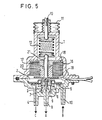
- Fig. 5 shows a further embodiment of the pressure regulator according to the invention, wherein additionally an electromagnet 16 with a coil 17, pole plates 18 and 19 and an armature 20 with ram 21 are provided in the pressure regulator.
- the pressure regulator can also be operated without the aneroid bellow 11 if the electromagnet 16 is energized by an electronic system responding to changes in the atmospheric pressure. In order to be able to use the electromagnets 16 with a digital electronic system, this is expediently constructed for energization with a pulsed current.
- the pressure regulator represented in Fig. 5 can also be provided with a bellow 14 open towards the atmosphere according to the embodiment of Fig. 4, instead of with an aneroid bellow 11.
Landscapes
- Engineering & Computer Science (AREA)
- Physics & Mathematics (AREA)
- Chemical & Material Sciences (AREA)
- Combustion & Propulsion (AREA)
- Mechanical Engineering (AREA)
- General Engineering & Computer Science (AREA)
- Fluid Mechanics (AREA)
- General Physics & Mathematics (AREA)
- Automation & Control Theory (AREA)
- Control Of Fluid Pressure (AREA)
- Supercharger (AREA)
Claims (10)
Applications Claiming Priority (2)
| Application Number | Priority Date | Filing Date | Title |
|---|---|---|---|
| DE8130788U | 1981-10-21 | ||
| DE19818130788U DE8130788U1 (de) | 1981-10-21 | 1981-10-21 | Druckregler |
Publications (2)
| Publication Number | Publication Date |
|---|---|
| EP0077543A1 EP0077543A1 (de) | 1983-04-27 |
| EP0077543B1 true EP0077543B1 (de) | 1987-08-26 |
Family
ID=6732304
Family Applications (1)
| Application Number | Title | Priority Date | Filing Date |
|---|---|---|---|
| EP82109554A Expired EP0077543B1 (de) | 1981-10-21 | 1982-10-15 | Druckregler |
Country Status (5)
| Country | Link |
|---|---|
| US (1) | US4622815A (de) |
| EP (1) | EP0077543B1 (de) |
| JP (1) | JPS5880710A (de) |
| DE (2) | DE8130788U1 (de) |
| WO (1) | WO1987002153A1 (de) |
Families Citing this family (12)
| Publication number | Priority date | Publication date | Assignee | Title |
|---|---|---|---|---|
| DE4103769C1 (de) * | 1991-02-08 | 1992-06-17 | Draegerwerk Ag, 2400 Luebeck, De | |
| RU2193131C1 (ru) * | 2001-05-07 | 2002-11-20 | Тюменский государственный нефтегазовый университет | Дистанционно-управляемый регулятор |
| US7334799B2 (en) * | 2002-12-23 | 2008-02-26 | Caterpillar Inc. | Sealing device for a turbocharger |
| US8356693B2 (en) * | 2007-09-24 | 2013-01-22 | Honeywell International Inc. | Overboard vent valve for use in an aircraft bearing lubrication system |
| EP2335126A1 (de) * | 2008-10-14 | 2011-06-22 | Circor Instrumentation Technologies, Inc. | Verfahren und vorrichtung für niederleistungs- und/oder hochdruck-flusssteuerung |
| BR112013023308A2 (pt) * | 2011-03-21 | 2017-04-25 | Borgwarner Inc | turbocarregador |
| RU2477245C2 (ru) * | 2011-04-08 | 2013-03-10 | Открытое акционерное общество "Информационные спутниковые системы" имени академика М.Ф. Решетнёва" | Способ регулирования и стабилизации давления в рабочих установках сильфонного типа |
| US8794588B1 (en) * | 2011-08-04 | 2014-08-05 | Metrex Valve Corp. | High pressure actuator regulating valve |
| FR2979136B1 (fr) * | 2011-08-16 | 2014-11-14 | Snecma | Dispositif d'activation d'une vanne passive d'ejecteur pour pressurisation d'une enceinte de turboreacteur d'aeronef |
| WO2013180962A1 (en) * | 2012-05-31 | 2013-12-05 | Borgwarner Inc. | Actuator rod sealing system |
| CN110741146B (zh) * | 2018-05-19 | 2022-03-22 | 帕德米尼Vna机电私人有限公司 | 具有改善的空气辅助的双弹簧排气阀 |
| US10920902B2 (en) * | 2018-10-02 | 2021-02-16 | Senior Ip Gmbh | Bellows-enabled bleed valve |
Family Cites Families (13)
| Publication number | Priority date | Publication date | Assignee | Title |
|---|---|---|---|---|
| US3125111A (en) * | 1964-03-17 | Vacuum regulator | ||
| US1903338A (en) * | 1929-04-03 | 1933-04-04 | Burchard E Horne | Pressure regulating and relief valve |
| US2376199A (en) * | 1942-03-31 | 1945-05-15 | Gen Electric | Control for aircraft superchargers |
| US2596178A (en) * | 1948-10-12 | 1952-05-13 | Seeler Henry | Pressure responsive regulator |
| US3035408A (en) * | 1960-01-04 | 1962-05-22 | Garrett Corp | Waste gate control for supercharger turbines |
| US3611711A (en) * | 1969-11-06 | 1971-10-12 | Trw Inc | Turbocharger control |
| JPS52121823A (en) * | 1976-04-05 | 1977-10-13 | Aisin Seiki | High compensating valve device |
| US4108197A (en) * | 1977-02-23 | 1978-08-22 | Robertshaw Controls Company | Condition response differential vacuum regulator and method of making the same |
| JPS5533513A (en) * | 1978-08-29 | 1980-03-08 | Kuraray Co Ltd | Swirl fluidized-bed type heat exchanger |
| JPS595772B2 (ja) * | 1979-01-10 | 1984-02-07 | 株式会社日立製作所 | 排気バイパス式タ−ボチヤ−ジヤ |
| US4283912A (en) * | 1979-06-12 | 1981-08-18 | The Garrett Corporation | Turbocharger control |
| EP0035691B1 (de) * | 1980-03-07 | 1983-06-15 | Bayerische Motoren Werke Aktiengesellschaft, Patentabteilung AJ-3 | Ladedruck-Regelvorrichtung für Brennkraftmaschinen |
| US4391290A (en) * | 1980-10-23 | 1983-07-05 | General Electric Company | Altitude sensing control apparatus for a gas turbine engine |
-
1981
- 1981-10-21 DE DE19818130788U patent/DE8130788U1/de not_active Expired
-
1982
- 1982-10-15 DE DE8282109554T patent/DE3277089D1/de not_active Expired
- 1982-10-15 EP EP82109554A patent/EP0077543B1/de not_active Expired
- 1982-10-21 US US06/485,577 patent/US4622815A/en not_active Expired - Fee Related
- 1982-10-21 WO PCT/EP1982/000233 patent/WO1987002153A1/en not_active Ceased
- 1982-10-21 JP JP57183802A patent/JPS5880710A/ja active Pending
Also Published As
| Publication number | Publication date |
|---|---|
| DE8130788U1 (de) | 1982-03-25 |
| JPS5880710A (ja) | 1983-05-14 |
| DE3277089D1 (en) | 1987-10-01 |
| US4622815A (en) | 1986-11-18 |
| WO1987002153A1 (en) | 1987-04-09 |
| EP0077543A1 (de) | 1983-04-27 |
Similar Documents
| Publication | Publication Date | Title |
|---|---|---|
| US5063744A (en) | Actuator for controlling intake pressure in sequential turbo-system | |
| US4188972A (en) | Gas valve assembly | |
| US4161929A (en) | Exhaust gas recirculation control system for an internal combustion engine | |
| US4589254A (en) | Regenerator for diesel particulate filter | |
| US4622815A (en) | Pressure regulator | |
| US4174617A (en) | Turbocharger control system | |
| US4211081A (en) | Exhaust bypassing system for a turbocharger | |
| US4467775A (en) | Method and apparatus for controlling recirculated quantities of exhaust gas in internal combustion engines | |
| US6898933B2 (en) | Method for determining a boost pressure setpoint in an internal combustion engine with an exhaust gas turbocharger | |
| US4519210A (en) | Turbocharged internal combustion engine with apparatus for controlling supercharging pressure | |
| EP0111196B1 (de) | Regelvorrichtung für eine Turboladereinheit zur Aufladung einer Brennkraftmaschine | |
| US3866583A (en) | Mixture control system for an internal combustion engine with controlled injection fuel | |
| EP0193758A3 (de) | Steuersystem von Turbolader | |
| US6178748B1 (en) | Altitude compensating wastegate control system for a turbocharger | |
| EP0084723B1 (de) | Ladedruckregelung mit Höhenkorrektur | |
| US4387572A (en) | Turbocharger control system | |
| EP0084737A3 (de) | Abgasrückführregelverfahren für Brennkraftmaschine | |
| US4187811A (en) | Exhaust gas recirculation system of an internal combustion engine | |
| GB1459720A (en) | Fuel control for a gas turbine engine having auxiliary air bleed | |
| US4433661A (en) | Device for the speed-dependent closure limitation of a carburettor main throttle | |
| JPH0750418B2 (ja) | 空気圧レギユレ−タ | |
| US4236376A (en) | Arrangement for regulating supercharger air pressure | |
| US4445475A (en) | Engine idling speed control systems | |
| CN115789304A (zh) | 一种真空断路器调压阀 | |
| CA1153276A (en) | Low-differential pressure delay valve |
Legal Events
| Date | Code | Title | Description |
|---|---|---|---|
| PUAI | Public reference made under article 153(3) epc to a published international application that has entered the european phase |
Free format text: ORIGINAL CODE: 0009012 |
|
| AK | Designated contracting states |
Designated state(s): DE FR GB IT SE |
|
| 17P | Request for examination filed |
Effective date: 19830816 |
|
| ITF | It: translation for a ep patent filed | ||
| GRAA | (expected) grant |
Free format text: ORIGINAL CODE: 0009210 |
|
| AK | Designated contracting states |
Kind code of ref document: B1 Designated state(s): DE FR GB IT SE |
|
| REF | Corresponds to: |
Ref document number: 3277089 Country of ref document: DE Date of ref document: 19871001 |
|
| ET | Fr: translation filed | ||
| PLBE | No opposition filed within time limit |
Free format text: ORIGINAL CODE: 0009261 |
|
| STAA | Information on the status of an ep patent application or granted ep patent |
Free format text: STATUS: NO OPPOSITION FILED WITHIN TIME LIMIT |
|
| 26N | No opposition filed | ||
| PG25 | Lapsed in a contracting state [announced via postgrant information from national office to epo] |
Ref country code: GB Effective date: 19891015 |
|
| PG25 | Lapsed in a contracting state [announced via postgrant information from national office to epo] |
Ref country code: SE Effective date: 19891016 |
|
| PGFP | Annual fee paid to national office [announced via postgrant information from national office to epo] |
Ref country code: DE Payment date: 19891020 Year of fee payment: 8 |
|
| GBPC | Gb: european patent ceased through non-payment of renewal fee | ||
| PG25 | Lapsed in a contracting state [announced via postgrant information from national office to epo] |
Ref country code: FR Effective date: 19900629 |
|
| REG | Reference to a national code |
Ref country code: FR Ref legal event code: ST |
|
| PG25 | Lapsed in a contracting state [announced via postgrant information from national office to epo] |
Ref country code: DE Effective date: 19910702 |
|
| EUG | Se: european patent has lapsed |
Ref document number: 82109554.4 Effective date: 19900705 |