EP0077568A2 - Schalter mit programmierbarer Betätigung - Google Patents
Schalter mit programmierbarer Betätigung Download PDFInfo
- Publication number
- EP0077568A2 EP0077568A2 EP82109649A EP82109649A EP0077568A2 EP 0077568 A2 EP0077568 A2 EP 0077568A2 EP 82109649 A EP82109649 A EP 82109649A EP 82109649 A EP82109649 A EP 82109649A EP 0077568 A2 EP0077568 A2 EP 0077568A2
- Authority
- EP
- European Patent Office
- Prior art keywords
- circuit breaker
- module
- breaker according
- circuit
- metallic element
- Prior art date
- Legal status (The legal status is an assumption and is not a legal conclusion. Google has not performed a legal analysis and makes no representation as to the accuracy of the status listed.)
- Withdrawn
Links
Images
Classifications
-
- H—ELECTRICITY
- H01—ELECTRIC ELEMENTS
- H01H—ELECTRIC SWITCHES; RELAYS; SELECTORS; EMERGENCY PROTECTIVE DEVICES
- H01H83/00—Protective switches, e.g. circuit-breaking switches, or protective relays operated by abnormal electrical conditions otherwise than solely by excess current
- H01H83/20—Protective switches, e.g. circuit-breaking switches, or protective relays operated by abnormal electrical conditions otherwise than solely by excess current operated by excess current as well as by some other abnormal electrical condition
- H01H2083/206—Protective switches, e.g. circuit-breaking switches, or protective relays operated by abnormal electrical conditions otherwise than solely by excess current operated by excess current as well as by some other abnormal electrical condition with thermal shunt trip
Definitions
- the present invention relates to the improvement of an electrical circuit breaker module of known type, incorporating a conventional circuit breaker.
- the improvement consists in inserting into the module a controlled switch for triggering or engaging the bypass circuit associated with the module.
- This controlled switch is housed in the module without having to make any modification whatsoever to its thickness (height of the front wall), along the vertical plane, as well as to its depth.
- the utility value of an electric circuit breaker module inside a connection box is obvious and this value is increased when the module includes an additional controlled switch used to engage or trigger the electrical bypass circuit with which it is associated.
- the activation of the controlled switch can be controlled remotely from the connection box so as to activate it when necessary or using programmable or non-programmable control automations. This then results in a control of each electrical branch circuit of a connection box or of those which it is thus desired to control so as to control the supply of the electrical charges connected to each of the circuits.
- Another important advantage inherent in this improved circuit breaker module is that the user has the ability to automatically control a variety of electrical branch circuits.
- timer devices or other programmable devices it is possible to control the switching on or off of lighting or other electrical devices at predetermined times of the day when the premises are unoccupied or during periods vacation. Such an operation of electrical devices would then simulate an occupation of the premises.
- Another advantage of this type of electrical circuit breaker module lies in the ability to manage the distribution of loads, which leads to energy conservation with regard in particular: the electric heating systems which can be programmed for n '' be operated only at predetermined times and / or in response to changes in temperature.
- Another characteristic resides in a controlled switch element which is small enough to be incorporated into a circuit breaker module and which requires a relatively low power supply for its operation with a view to switching on and off electrical branch circuits of 110 or 220 volts or other similar low voltage branch circuits below 600 volts.
- a characteristic of the present invention resides in the production of an improved electrical circuit breaker module which meets the needs stated above and which is substantially free from all the disadvantages of the device of the prior art mentioned above.
- Another characteristic of the present invention consists of an electric circuit breaker module which incorporates a conventional circuit breaker and a switch device controlled inside the same module without modifying the thickness of the module, along a vertical plane.
- Another characteristic of the present invention is to provide an improved circuit breaker module which has a controlled switch device, the control of which is carried out from a place remote from a connection box and / or automatically by the user or a scheduling device.
- Another characteristic of the present invention resides in an improved electrical circuit breaker module which has a conventional circuit breaker and a switching device: controlled and which can adapt to an existing connection box which incorporates a plurality of conventional electrical circuit breaker modules without it it is necessary to - move the already wired existing modules.
- Another characteristic of the present invention resides in the production of an improved electric circuit breaker module comprising a conventional circuit breaker and a controlled switch device and which is relatively inexpensive to manufacture and install.
- the present invention relates to an improvement of an electrical circuit breaker module, plug-in, of small size, and which is mounted superimposed in columns by stacking on a plurality of modules at the inside of an electrical connection box.
- Each of the modules is respectively connected to electrical branch circuits and is provided with circuit interruption means for disconnecting the branch circuit with which it is associated at the time of an overcurrent or a fault on the branch circuit.
- the improvement includes a controlled switch means mounted in at least one of the modules, without modifying the thickness of the module, according to a vertical plane, and its depth. This controlled switch means is connected in series by means of a circuit switch and is put into operation using an external or internal control means of the module which governs the open or closed state of the contacts.
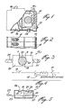
- the electrical circuit breaker module of the present invention is generally designated by the reference 10.
- the module consists of a conventional enclosure formed of an insulating material and houses a switch mechanical 16 coupled to an overcurrent protection element 12 (see Figure 4).
- circuit breaker modules 10 are usually fixed to a connection box by stacking one on the other.
- Each module may include one or more marking connections 13 and one or more electrical connections 14 so as to connect a module to a particular electrical branch circuit among the plurality of circuits entering and leaving the connection box, as is well known in art.
- the modules can also be of the type which can incorporate fusible elements of the screw or cartridge type. tubular which can be fixed in a removable way on the front of the module.
- These modules are of different construction from those illustrated in Figures 1 and 2 but are similarly stacked on top of each other and / or side by side.
- the present invention relates to an improvement of such a circuit breaker module in which a controlled switch element 15 is inserted inside this same module 10 without having to modify the thickness of the module taken along the vertical plane. As illustrated in Figure 4, this switch element 1.5 is connected in series with the circuit breaker element 12. As shown in Figure 2, the circuit breaker module is provided with a manual control button 16 allowing the circuit breaker to occupy the position "ON” or "OFF".
- the controlled switch device 15 it is operated remotely, relative to the connection box and can be activated using an electrical signal, in this case a low power source connected to socket 18 enabling the switch element 15 to be activated or deactivated.
- the command may be produced by the user himself and / or the operating company which owns the energy transport network. It is also conceivable the possibility of controlling the switch element 15 according to an established schedule so as to engage and trip the electrical circuit coupled to the circuit breaker module 10 at hours and according to predetermined conditions during the day so as to control various electrical devices connected to the branch circuits.
- the switch element 15 may consist of an electronic switch or other means. All that is actually required is that the switch is of relatively small size and is capable of operating at very low power and that it is further able to engage and trip branch circuits operating at voltages of 110 or 220 Volts for example, which correspond to the voltages usually used at the residential and commercial level.
- the switching element 15 consists of a thermo-mechanical switch comprising an actuating element formed of a bi-metallic disc 19, sensitive to temperature, on which is fixed a heating conductive element 20 capable of causing deformation of the disc when it is heated.
- the disc is of concave / convex construction and formed of a bi-metallic material so that the heating of the disc causes it to expand and move from its normal position to another position designated by 19 'in Figure 5.
- the disc 19 is held by means of a rigid side wall 26 which allows the deflection of the disc in the position 19 '.
- a rigid rod 17 connects the lower surface 21 of the disc 19 to the arm 22 of the switch so that when the disc is heated and occupies the position shown in 19 ', the contact 22 is open (as shown by the dotted lines) opening thus the associated branch circuit 23 connected to the circuit breaker module housing the switch element 15.
- 1e disc 19 has a circular configuration while the filiform heating element 20 is arranged in a serpentine over a large part of the surface of the disc 19.
- the disc 19 can also be formed from a bi-band. rectangular metal.
- the switch is actuated by applying a voltage across terminals A and B of the threadlike heating element.
- the enclosure 24 of the switch is connected in series to line 23 of the branch circuit using the end conductors 25.
- thermo-mechanical disc switch lies in the very low power required for actuation.
- the construction of the disc allows rapid action to interrupt the supply of the electric circuit 23 which can be subjected to a current of 30 amps, for example.
- this switch allows it to be incorporated inside the module housing the conventional circuit breaker and to achieve the various advantages described above.
Landscapes
- Breakers (AREA)
- Thermally Actuated Switches (AREA)
Applications Claiming Priority (2)
| Application Number | Priority Date | Filing Date | Title |
|---|---|---|---|
| US06/313,214 US4434413A (en) | 1981-10-20 | 1981-10-20 | Electrical circuit breaker module |
| US313214 | 1981-10-20 |
Publications (2)
| Publication Number | Publication Date |
|---|---|
| EP0077568A2 true EP0077568A2 (de) | 1983-04-27 |
| EP0077568A3 EP0077568A3 (de) | 1985-10-23 |
Family
ID=23214818
Family Applications (1)
| Application Number | Title | Priority Date | Filing Date |
|---|---|---|---|
| EP82109649A Withdrawn EP0077568A3 (de) | 1981-10-20 | 1982-10-19 | Schalter mit programmierbarer Betätigung |
Country Status (4)
| Country | Link |
|---|---|
| US (1) | US4434413A (de) |
| EP (1) | EP0077568A3 (de) |
| JP (1) | JPS58135534A (de) |
| CA (1) | CA1184224A (de) |
Cited By (2)
| Publication number | Priority date | Publication date | Assignee | Title |
|---|---|---|---|---|
| FR2574218A1 (fr) * | 1984-12-03 | 1986-06-06 | Merlin Gerin | Effecteur pour une installation modulaire de distribution domestique et de gestion d'energie electrique |
| WO1998002896A1 (en) * | 1996-07-15 | 1998-01-22 | Gewiss S.P.A. | Modular automatic electric breaker with optimization of used spaces |
Families Citing this family (4)
| Publication number | Priority date | Publication date | Assignee | Title |
|---|---|---|---|---|
| US4616206A (en) * | 1984-09-07 | 1986-10-07 | Eaton Corporation | Circuit breaker and shunt trip apparatus combined within single pole device |
| US5373411A (en) * | 1991-09-30 | 1994-12-13 | Eaton Corporation | Remote control circuit breaker system |
| US5301083A (en) * | 1991-09-30 | 1994-04-05 | Eaton Corporation | Remote control residential circuit breaker |
| AUPQ831100A0 (en) * | 2000-06-22 | 2000-07-13 | Alcatel | Bi-stable microswitch including shape memory alloy latch |
Family Cites Families (5)
| Publication number | Priority date | Publication date | Assignee | Title |
|---|---|---|---|---|
| US2471924A (en) * | 1943-07-10 | 1949-05-31 | Metals & Controls Corp | Thermal relay |
| US3566327A (en) | 1970-05-04 | 1971-02-23 | Ite Circuit Breaker Ltd | Combined direct and indirect thermally calibrated bimetal |
| US4047140A (en) | 1975-12-23 | 1977-09-06 | Westinghouse Electric Corporation | Thermal overload relay |
| US4164719A (en) * | 1978-04-03 | 1979-08-14 | Gould Inc. | Load management apparatus for residential load centers |
| US4272687A (en) * | 1979-03-05 | 1981-06-09 | Borkan William N | Power manageable circuit breaker |
-
1981
- 1981-10-20 US US06/313,214 patent/US4434413A/en not_active Expired - Lifetime
-
1982
- 1982-04-21 CA CA000401371A patent/CA1184224A/fr not_active Expired
- 1982-10-19 JP JP57184412A patent/JPS58135534A/ja active Pending
- 1982-10-19 EP EP82109649A patent/EP0077568A3/de not_active Withdrawn
Cited By (2)
| Publication number | Priority date | Publication date | Assignee | Title |
|---|---|---|---|---|
| FR2574218A1 (fr) * | 1984-12-03 | 1986-06-06 | Merlin Gerin | Effecteur pour une installation modulaire de distribution domestique et de gestion d'energie electrique |
| WO1998002896A1 (en) * | 1996-07-15 | 1998-01-22 | Gewiss S.P.A. | Modular automatic electric breaker with optimization of used spaces |
Also Published As
| Publication number | Publication date |
|---|---|
| EP0077568A3 (de) | 1985-10-23 |
| CA1184224A (fr) | 1985-03-19 |
| JPS58135534A (ja) | 1983-08-12 |
| US4434413A (en) | 1984-02-28 |
Similar Documents
| Publication | Publication Date | Title |
|---|---|---|
| EP0177380B1 (de) | Schaltvorrichtung mit veränderlicher Zusammensetzung mittels Zusammenbau von modularen Elementen | |
| FR2786924A1 (fr) | Fusible thermique | |
| EP2602805B1 (de) | Housing for overvoltage protection device and related overvoltage protection device | |
| FR2492157A1 (fr) | Dispositif combine de demarrage et de protection de moteur electrique monophase utilisant une thermistance de demarrage | |
| CA1184224A (fr) | Coupe-circuit a commande programmable | |
| FR2480030A1 (fr) | Disjoncteur reenclenchable a distance et insensensible aux variations de temperature ambiante | |
| FR2568408A1 (fr) | Dispositif pour la verification des fusibles | |
| US6057751A (en) | Overheat and overload sensing device | |
| EP2743959B1 (de) | Thermische Auslösvorrichtung und Schutzschalter mit dieser Vorrichtung | |
| EP0834975B1 (de) | Elektrisches Verteilungsanschlusselement mit hybridem Begrenzerblock | |
| EP2743958B1 (de) | Elektrisches Stromschaltgerät, insbesondere Abzweigschalter | |
| EP0218491B1 (de) | Hilfsanordnung für das elektrische Schalten, insbesondere für relais mit Kontakten, Schürze oder gleichartige fernbetätigte Anordnungen | |
| FR2935834A1 (fr) | Dispositif de commutation d'un courant electrique et vehicule automobile equipe d'un coffret de repartition electrique comportant un tel dispositif | |
| EP0881653A1 (de) | Sicherungshalter so wie Schachtsicherung für elektrische Geräte | |
| FR2879033A1 (fr) | Dispositif de protection d'une installation electrique, procede et utilisation correspondants | |
| FR2583192A1 (fr) | Perfectionnement aux appareils de telecommande electriques | |
| EP0782757B1 (de) | Vorrichtung zur leistungsbegrenzung für elektroinstallation | |
| EP2743957B1 (de) | Gerät zur Stromunterbrechung, insbesondere Anschluss-Überlastschalter | |
| FR2771587A1 (fr) | Relais-shunt pour lampe electrique basse tension, montee en serie | |
| EP0089903A1 (de) | Steckdose mit Fehlerstromschutz | |
| EP2743956B1 (de) | Gerät zur Stromunterbrechung, insbesondere Anschluss-Überlastschalter | |
| EP0579568A1 (de) | Zweipoliger Schalter | |
| FR2902232A1 (fr) | Commutateur pour dispositif de derivation d'un composant electrique | |
| FR2767766A1 (fr) | Dispositif pour interdire l'usage non autorise d'un vehicule a moteur ayant recours a un demarreur et en agissant sur et dans celui-ci | |
| FR2703207A1 (fr) | Dispositif de chauffage électrique. |
Legal Events
| Date | Code | Title | Description |
|---|---|---|---|
| PUAI | Public reference made under article 153(3) epc to a published international application that has entered the european phase |
Free format text: ORIGINAL CODE: 0009012 |
|
| AK | Designated contracting states |
Designated state(s): AT BE CH DE FR GB IT LI LU NL SE |
|
| PUAL | Search report despatched |
Free format text: ORIGINAL CODE: 0009013 |
|
| AK | Designated contracting states |
Designated state(s): AT BE CH DE FR GB IT LI LU NL SE |
|
| 17P | Request for examination filed |
Effective date: 19860122 |
|
| 17Q | First examination report despatched |
Effective date: 19860919 |
|
| STAA | Information on the status of an ep patent application or granted ep patent |
Free format text: STATUS: THE APPLICATION IS DEEMED TO BE WITHDRAWN |
|
| 18D | Application deemed to be withdrawn |
Effective date: 19870130 |
|
| RIN1 | Information on inventor provided before grant (corrected) |
Inventor name: PELLETIER, JEAN-MARC Inventor name: DION, YVON |