EP0077574B1 - Spracherkennungssystem für Kraftwagen - Google Patents
Spracherkennungssystem für Kraftwagen Download PDFInfo
- Publication number
- EP0077574B1 EP0077574B1 EP82109698A EP82109698A EP0077574B1 EP 0077574 B1 EP0077574 B1 EP 0077574B1 EP 82109698 A EP82109698 A EP 82109698A EP 82109698 A EP82109698 A EP 82109698A EP 0077574 B1 EP0077574 B1 EP 0077574B1
- Authority
- EP
- European Patent Office
- Prior art keywords
- signal
- level
- threshold
- spoken instruction
- comparator
- Prior art date
- Legal status (The legal status is an assumption and is not a legal conclusion. Google has not performed a legal analysis and makes no representation as to the accuracy of the status listed.)
- Expired
Links
- 238000001514 detection method Methods 0.000 claims description 45
- 238000004364 calculation method Methods 0.000 claims description 13
- 230000004044 response Effects 0.000 claims description 13
- 238000005070 sampling Methods 0.000 claims description 12
- 230000003466 anti-cipated effect Effects 0.000 claims 1
- 238000000034 method Methods 0.000 description 8
- 238000010586 diagram Methods 0.000 description 6
- 238000000605 extraction Methods 0.000 description 4
- 230000008569 process Effects 0.000 description 4
- 238000001228 spectrum Methods 0.000 description 4
- 230000006870 function Effects 0.000 description 3
- 230000003111 delayed effect Effects 0.000 description 2
- 230000001419 dependent effect Effects 0.000 description 2
- 230000000994 depressogenic effect Effects 0.000 description 2
- 238000010606 normalization Methods 0.000 description 2
- 230000002238 attenuated effect Effects 0.000 description 1
- 230000001010 compromised effect Effects 0.000 description 1
- 230000000881 depressing effect Effects 0.000 description 1
- 230000004069 differentiation Effects 0.000 description 1
- 238000010200 validation analysis Methods 0.000 description 1
Images




Classifications
-
- G—PHYSICS
- G10—MUSICAL INSTRUMENTS; ACOUSTICS
- G10L—SPEECH ANALYSIS TECHNIQUES OR SPEECH SYNTHESIS; SPEECH RECOGNITION; SPEECH OR VOICE PROCESSING TECHNIQUES; SPEECH OR AUDIO CODING OR DECODING
- G10L25/00—Speech or voice analysis techniques not restricted to a single one of groups G10L15/00 - G10L21/00
- G10L25/78—Detection of presence or absence of voice signals
- G10L25/87—Detection of discrete points within a voice signal
-
- G—PHYSICS
- G10—MUSICAL INSTRUMENTS; ACOUSTICS
- G10L—SPEECH ANALYSIS TECHNIQUES OR SPEECH SYNTHESIS; SPEECH RECOGNITION; SPEECH OR VOICE PROCESSING TECHNIQUES; SPEECH OR AUDIO CODING OR DECODING
- G10L15/00—Speech recognition
- G10L15/20—Speech recognition techniques specially adapted for robustness in adverse environments, e.g. in noise, of stress induced speech
Definitions
- the present invention relates generally to a speech recognition system for an automotive vehicle, and more particularly to a speech recognition system by which driver's spoken instructions can be reliably recognized even as engine noise fluctuates within the passenger compartment.
- the speech recognizer is used in a relatively quiet environment; however, the speech recognition system for an automotive vehicle is usually used within a relatively noisy passenger compartment and additionally the noise level fluctuates intensely. Therefore, one of the major problems is how to cope with erroneous spoken phrase recognitions caused by fluctuating engine noise within the passenger compartment.
- a voice detector in the speech recognizer by which the start and the end of a spoken instruction are determined by detecting whether the magnitude of a spoken instruction signal exceeds a predetermined reference threshold voltage level for a predetermined period of time or whether the magnitude of the spoken instruction signal drops below the predetermined reference threshold voltage level for another predetermined period of time, respectively.
- the prior-art speech recognizer since the reference threshold voltage level is fixed, when the noise signal level is high, for instance, when the vehicle is running within a tunnel and therefore the noise level exceeds the reference threshold voltage level for a long time, there exists a problem in that the voice detector can erroneously consider this state to represent the beginning of a spoken instruction. In other words, the prior-art speech recognizer is prone to erroneous recognition due to an intense noise within the passenger compartment.
- a more reliable speech recognition with respect to the background noise is possible with a known speech-tone discrimination system including a signal presence detector (IBM Technical Disclosure Bulletin, Vol. 11, No. 4, September 1968, page 417-419).
- This system includes a signal presence detector, a signal validation circuit and a speech-tone discrimination circuit.
- the signal presence detector detects the presence of an input signal by a fixed signal-to-noise ratio threshold. The average noise level is established during intervals when the signal is absent. For the signal presence detection, the logarithm of the magnitude of the rectified signal is taken. When the rectified input signal exceeds the noise threshold by a certain value a signal present command is outputted and the noise average value is held constant until the rectified signal again drops below the threshold value.
- this known system provides for an improved differentiation between a speech signal and background noise, since the noise level is established only during the absent time of the speech signal it cannot cope with different magnitudes of the speech signal nor with a sudden increase of the noise level during inputting of a command.
- Another known speech recognition system in particular for telephone channels makes use of the different time contants of the band limited envelope of an amplitude modulated wave consisting of a carrier frequency (e.g. 300 to 3400 Hz) and the modulating signal (envelope 0 to 100 Hz).
- the envelope referring to the background noise is substantially constant over certain time periods and the presence of useful speech information is detected depending upon a comparison of various segments of the envelope for a certain voice channel over different time periods.
- the system needs modulators and demodulators and may be useful for telephone channels however not for speech recognition systems using short spoken commands for instructing an actuator in an automotive vehicle with abrupt changes of the background noise level.
- the speech recognition system for an automotive vehicle having a speech recognizer which can activate an actuator in response to a spoken instruction inputted through a microphone comprises the features (a) to (h) of claim 1.
- the speech recognition system can be embodied by a microcomputer executing the same or similar processes, calculations and/or operations.
- Fig. 1 shows a schematic block diagram of a typical speech recognizer 100.
- the user To use the speech recognizer, the user must first record a plurality of predetermined spoken instructions. Specifically, in this spoken instruction recording mode (reference mode), the user first depresses a record switch 1 disposed near the user. When the record switch 1 is depressed, a switch input interface 4 detects the depression of the record switch 1 and outputs a signal to a controller 5 via a wire 4a. In response to this signal, the controller 5 outputs a recording mode command signal to other sections in order to preset the entire speech recognizer to the recording mode.
- this spoken instruction recording mode reference mode
- the controller 5 outputs a recording mode command signal to other sections in order to preset the entire speech recognizer to the recording mode.
- the spoken instruction recording mode when the user says a phrase to be used as a spoken instruction, such as "open doors", near a microphone 2, the spoken phrase is transduced into a corresponding electric signal through the microphone 2, amplified through a speech input interface 6 consisting mainly of a spectrum-normalizing amplifier, smoothed through a root-mean-square (RMS) smoother 15 including a rectifier 15-1 and a smoother 15-2, and finally inputted to a voice detector 7.
- RMS root-mean-square
- the spectrum-normalizing amplifier amplifies the input at different gain levels at different frequencies, so as to adjust the naturally frequency-dependent power spectrum of human speech to a more nearly flat power spectrum.
- the voice detector 7 detects whether or not the magnitude of the spoken phrase signal exceeds a predetermined level for a predetermined period of time (150 to 250 ms) in order to recognize the start of the spoken phrase input signal and whether or not the magnitude of the signal drops below a predetermined level for a predetermined period of time (about 300 ms) in order to recognize the end of the signal. Upon detection of the start of the signal, this voice detector 7 outputs another recording mode command signal to the controller 5.
- the controller 5 activates a group of bandpass filters 8, so that the spoken phrase signal from the microphone 2 is divided into a number of predetermined frequency bands.
- the frequency-divided spoken phrase signals are squared or rectified therein in order to derive a voice power spectrum across the frequency bands and then converted into corresponding digital time-series matrix-phonetic pattern data (explained later).
- These data are then stored in a memory unit 10.
- the speech recognizer is set to the spoken instruction recording mode by the depression of the record switch 1
- the time-series matrix-phonetic pattern data are transferred to a reference pattern memory unit 11 and stored therein as reference data for use in recognizing the speech instructions.
- the user can input speech instructions, such as "open doors", to the speech recognizer through the microphone 2 while depressing a recognition switch 3.
- the switch input interface 4 detects the depression of the recognition switch 3 and outputs a signal t6 the controller 5 via a wire 4b.
- the control 5 outputs a recognition mode command signal to other sections in order to preset the entire speech recognizer to the recognition mode.
- the spoken phrase recognition mode when the user says an instruction phrase similar to the one recorded previously near the microphone 2 and when the voice detector 7 outputs a signal, the spoken instruction is transduced into a corresponding electric signal through the microphone 2, amplified through the speech input interface 6, filtered and divided into voice power spectra across the frequency bands through the band pass filters 8, squared or rectified and further converted into corresponding digital time-series matrix-phonetic pattern data through the parameter extraction section 9, and then stored in the memory unit 10, in the same manner as in the recording mode.
- the time-series matrix-phonetic pattern data stored in the memory unit 10 in the recognition mode are sequentially compared with the time-series matrix-phonetic pattern data stored in the reference pattern memory unit 11 in the recording mode by a resemblance comparator 12.
- the resemblance comparator 12 calculates the level of correlation of the inputted speech instruction to the reference speech instruction after time normalization and level normalization to compensate for variable speaking rate (because the same person might speak quickly and loudly at one time but slowly and in a whisper at some other time).
- the correlation factor is usually obtained by calculating the Tchebycheff distance (explained later) between recognition-mode time-series matrix-phonetic pattern data and recording-mode time-series matrix-phonetic pattern data.
- the correlation factor calculated by the resemblance comparator 12 is next given to a resemblance determination section 13 to determine whether or not the calculated values lie within a predetermined range, that is, to evaluate their cross- correlation. If within the range, a command signal, indicating that a recognition-mode spoken instruction having adequate resemblance to one of the recorded instruction phrases, is outputted to one of actuators 14 in order to open the vehicle doors, for instance.
- the above-mentioned operations are all executed in accordance with command signals outputted from the controller 5.
- the speech recognizer 100 comprises various discrete elements or sections; however, it is of course possible to embody the speech recognizer 100 with a microcomputer including a central processing unit, a read-only memory, a random-access memory, a clock oscillator, etc.
- the voice detector 7, the parameter extraction section 9, the memory 10, the reference pattern memory 11, the resemblance comparator 12 and the resemblance determination section 13 can all be incorporated within the microcomputer, executing the same or similar processes, calculations and/or operations as explained hereinabove.
- the digital time-series matrix-phonetic pattern data and the Tchebycheff distance are defined as follows:
- a first recognition-mode speech instruction e.g. OPEN DOORS
- the Tchebycheff distance can be obtained from the following expression:
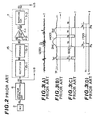
- Fig. 2 shows in more detail the speech detection section of the voice detecting means of the prior-art speech recognizer shown in Fig. 1, which is relevant for an understanding of the present invention.
- a spoken phrase inputted via a microphone and transduced into a corresponding electric signal (100) first passes through the speech input interface 6.
- the interface 6 is mainly made up of a spectrum-normalizing amplifier by which the electric signal is amplified to a greater degree at higher frequencies. This is because speech sounds tend to be attenuated greatly in the higher frequency range.
- the waveform of the spoken instruction signal (200) including noise outputted from the spectrum-normalizing amplifier 6 may appear as shown in Fig. 3(A).
- the amplified spoken instruction signal (200) is next applied to the bandpass filters 8 to begin the process of recognizing whether the signal is a correctly spoken instruction and to the RMS smoother 15, consisting mainly of the rectifier 15-1 and the smoother 15-2, to begin the process of detecting the start and end of the spoken phrase.
- the rectified and smooth spoken instruction signal (400) may appear as shown in Fig. 3(B), in which T, denotes a constant reference threshold voltage level.
- the smoothed signal (400) is then conducted to the voice detector 7 including a voltage level comparator 7-1 and a pulse duration comparator 7-2.
- the voltage level comparator 7-1 compares the voltage level of the smoothed signal with the predetermined reference threshold voltage level T f and outputs a H-voltage (high voltage) level pulse signal (600) only while the voltage level of the speech instruction signal exceeds the reference threshold level T f as depicted in Fig. 3(C).
- the pulse duration comparator 7-2 compares the pulse width of the H-voltage level pulse signal (600) with a predetermined reference spoken instruction start time t s and the pulse width of the L-voltage (low voltage) level pulse signal (600) with another predetermined reference end time t e and outputs a H-voltage level signal (700) only when the H-voltage level pulse width exceeds the reference start time t s and a L-voltage level signal (700) only when the L-voltage level pulse width exceeds the reference end time t e .
- the pulse duration comparator 7-2 outputs no H-voltage level signal.
- the pulse width of the second H-voltage level pulse signal is labeled t 2 , since t 2 is longer than the reference start time t s , the pulse duration comparator 7-2 outputs a H-voltage level signal, indicating the start of a spoken instruction.
- the H-voltage level start signal (700) from the pulse duration comparator 7-2 is delayed by the reference start time t s after the actual start time P of the spoken instruction. Thereafter, this H-voltage level start signal is outputted until the duration comparator 7-2 detects the end of speech instruction.
- the pulse duration comparator 7-2 outputs no L-voltage level signal, that is, duration comparator 7-2 sustains the H-voltage level signal.
- the pulse duration comparator 7-2 outputs a L-voltage level signal, indicating the end of speech instruction.
- the L-voltage level end signal from the duration comparator 7-2 is delayed by the reference end time t e after the actual end time P e of speech instruction. Thereafter, the end signal is outputted until the duration comparator 7-2 detects the start of another speech instruction.
- the controller 5 In response to the H-voltage level signal from the duration comparator 7-2 as shown in Fig. 3(D), the controller 5 outputs a command signal to activate the group of bandpass filters 8 and other sections to recognize the spoken instruction signal outputted from the spectrum-normalizing amplifier 6, as already explained.
- the speech recognizer cannot cope well with the fluctuations of noise level within the passenger compartment, with the result that accurate detection of speech instruction start and end is compromised so that noise may be interpreted as attempts at speech and/or spoken instructions may be ignored.
- the start of spoken instruction is detected on the basis of a threshold level varying according to the magnitude of the microphone input
- the end of the spoken instruction is detected on the basis of the threshold level fixed when the start of spoken instruction is detected. Therefore, even when noise level increases intensely after the start has been detected, it is possible to detect the end of spoken instruction reliably.
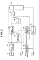
- Fig. 4 shows a first embodiment of a voice detecting means of the speech recognition system according to the present invention.
- the reference end threshold level is corrected to a higher level.
- the reference numeral 2 denotes a microphone
- the reference numeral 31 denotes a level detector for detecting the voltage level Sn of a spoken instruction signal including noise inputted from the microphone 2
- the reference numeral 32 denotes a threshold calculator for calculating threshold levels En on the basis of the voltage level data Sn outputted from the level detector 31 and a calculation expression
- the reference numeral 33 denotes a start comparator including a voltage level comparator and a pulse duration comparator for comparing the voltage level Sn from the level detector 31 with the threshold level En calculated by the threshold calculator 32 and the pulse duration M, of the signal from the voltage comparator with a reference start time ⁇ (W ⁇ ) in order to detect the start of the spoken instructions signal
- the reference numeral 34 denotes a timer unit for counting a predetermined time period T(L) beginning from when the start comparator 33 detects the start of spoken instruction.
- the reference numeral 35 denotes an OR gate
- the reference numeral 36 denotes a memory unit for storing the spoken instruction signal voltage level data Sn from the level detector 31 sequentially beginning from when the start of spoken instruction is detected or while the timer unit 34 is outputting a timer signal and for outputting these stored spoken instruction signal voltage level data Xm in the reverse order after the predetermined time period T has elapsed.
- the capacity of this memory unit 36 must be sufficient to store the data Sn outputted from the level detector 31 for at least the time period T pre- ' determined by the timer unit 34 (about one or two seconds).
- the reference numeral 37 denotes a threshold corrector for correcting the start-detection threshold level E calculated by the threshold calculator 32 in such a way that the calculated threshold level En is multiplied by a constant to a level S L obtained when the time T has elapsed after the start has been detected and is added to the start-detection threshold level E.
- the reference numeral 38 denotes an end comparator including another voltage level comparator and another pulse duration comparator for comparing the voltage level of the signal data Xm outputted from the memory unit 36 with the corrected threshold level E' from the threshold corrector 37, and the duration of the period in which X m exceeds E' with a reference end time ⁇ 3 (W 3 ) in order to detect the end of the spoken instruction signal.
- the voltage level of the signal is detected by the level detector 31.
- the detected voltage level data Sn are processed by the threshold calculator 32 on the basis of a predetermined calculation expression to obtain a reference start threshold level En.
- the detected signal level data Sn are compared sequentially with the calculated reference start threshold level En by the start comparator 33 with respect to voltage level and pulse duration as in the Fig. 6 embodiment.
- a spoken instruction start command signal outputted from the start comparator 33 activates the controller 5 (Fig.
- the memory unit 36 so as to store the voltage level data Sn outputted from the level detector 31 and the timer unit 34 so as to start counting a predetermined time period T.
- the memory unit 36 stops storing the spoken instruction voltage level data Sn.
- the timer unit T stops counting it outputs a L-voltage level signal to the memory unit 36 via the OR gate 35 and to, the threshold corrector 37 directly.
- the memory unit 36 outputs the spoken instruction voltage level data Xm previously stored after the start has been detected, in the reverse order, to the end comparator 38; the threshold corrector 37 multiplies the reference threshold level En obtained at the start detection and outputs the multiplied threshold level E' to the end comparator 38. Therefore, the read level data Xm are compared sequentially in the reverse order beginning from when the predetermined time T has elapsed after detection of spoken instruction start, with the multiplied threshold level E' by the end comparator 38 with respect to pulse voltage level and pulse duration.
- a spoken instruction end command signal outputted from the end comparator 38 activates the controller 5 (Fig. 1) so as to output another command signal to the entire system for stopping recognizing the spoken instruction.
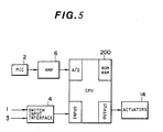
- Fig. 5 shows a second embodiment of a voice detecting means of the speed recognition system according to the present invention.
- the level detector 31, the threshold calculator 32, the start comparator 33, the timer unit 34, the OR gate 35, the memory unit 36, the threshold corrector 37 and the end comparator 38 described in the first embodiment shown in Fig. 4 are all incorporated within a microcomputer 200 provided with an analog-to-digital converter, a central processing unit, a read-only memory, a random-access memory, and input/output interfaces, etc. That is to say, some of the functions of the voice detecting means are implemented via arithmetic operations executed in accordance with appropriate software, in place of hardware.
- various elements or sections such as parameter extraction section 9, the memory 10, the reference pattern memory 11, the resemblance comparator 12, the resemblance determination section 13, the controller 5, etc. are all incorporated within the microcomputer 200 which performs the same functions as those of the above-mentioned discrete elements or sections in accordance with appropriate program stored therein.
- the microcomputer 200 On the basis of digital signals representative of the spoken instruction signal inputted via the microphone 2, the microcomputer 200 detects the start and end of the spoken instruction in the same way as described already with reference to Fig. 4.
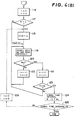
- Figs. 6(A) and (B) are flowcharts showing the steps of processing the digital signals from the A-D converter in order to obtain the spoken instruction start and end command signals;
- Figs. 7(A) and (B) are time charts showing example waveforms of spoken instruction signals.
- Program control first resets the time suffix n (in block 100) for incrementing the time suffix n in order (in block 101). Further, program control initializes the numbers of start-detection sample number M 1 , sampling-stop sample number M 2 and the start detection code M 3 (in block 102), and additionally replaces the start threshold level E with the calculation threshold level En (in block 103). At any given time n, spoken instruction signal voltage level data Sn are inputted (in block 104).
- the current calculation threshold level En is calculated on the basis of, for instance, the following expression (in block 105): where En indicates the mean threshold level over the time interval from 1 to p, where p is a fixed time period and a and ⁇ denote constants.
- the sample level Sn are compared with the calculation threshold level En (in block 106). If Sn is below En (in block 106) and therefore the start detection code is "0" (in block 107), since this indicates that the sampled signal level is lower than the calculated threshold level and therefore the start is not yet detected, the program returns to block 101 for repeating the same operations from block 101 to block 107.
- the start-detection sample number M 1 is incremented (in block 108).
- M 1 is compared with the reference start-detection sample number W 1 corresponding to a reference start time ⁇ 1 (reference start time ts in Figs. 5 and 7) (in block 109). For instance, if the sampling time interval is 9 ms and the time T1 is 72 ms, W 1 is 8.
- the start-detection code M 3 is set to "1" indicating that the start detection is completed and at the same time the sampling-stop sample number M 2 is reset (described later) (in block 110). From this moment, the sample level data Sn are stored in the memory sequentially as stored voltage level data Xm (in block 112). If M 1 is below W 1 (in block 109), since this indicates that the sampled spoken instruction level data Sn exceeds the calculated threshold level En for less than the reference start time T1 because of, for instance, noise, the program returns to block 107. In this state, since of course, the start detection code M 3 is still "0", the program is repeated beginning from block 101.
- start-detection sample number M 1 exceeds the reference start-detection sample number W, (in block 109), since the start-detection code M 3 is set to "1" (in block 110), even if the sample voltage level data Sn drops below the calculation threshold level En (in block 106) after the start has been detected, M 3 is already “1” (in block 107) and therefore the sample data Sn are stored sequentially in the memory (in block 112).
- start-detection code M 3 is "1" (in block 107)
- start-detection sample number M 1 and the sampling-stop sample number M 2 are both incremented (in block 111).
- M 2 is compared with the reference sampling stop sample number W 2 corresponding to a time T2 (for instance 40) (in block 113). If M 2 exceeds W 2 , the program stops storing the data in the memory because Sn drops below En for more than a reference stop time T2 , advancing the succeeding step of detecting spoken instruction end (block 116) shown in Fig. 6(B). If M 2 is below W 2 since this indicates that Sn does not yet drop below En for more than T2 , n is incremented (in block 114). And, if M 1 exceeds the timer sample number L, the sample voltage level data Sn are stopped from being stored in the memory. If M 1 is below L, program returns to block 104 for repeating the same steps.
- Program control first resets the time suffix r and the end-detection sample number V (in block 116).
- the start-detection sample number M 1 is compared with the timer sample number L (in block 117). If M 1 is equal to L, that is, the time period T determined by the timer has elapsed, the threshold level E is replaced with E+S L (where E denotes the start threshold level and S L denotes the sample voltage level obtained at the last sampling time interval (in block 118).
- This threshold correction corresponds to the threshold corrector 37 shown in Fig. 4. In this correction, it is also possible to replace it with the threshold level E L calculated on the level data sampled after the time period T has elapsed or obtained by adding a constant to the threshold level E.
- the data Xm stored in the memory unit are read in the reverse order sequentially (in block 119) and compared with the replaced threshold level E'--+(E+Sd (in block 120).
- the time suffix r and end-detection sample number V are both incremented (in block 121).
- Xm is below the E', only r is incremented but V is reset to "0" (in block 122), returning to block 119.
- the end detection sample number V is compared with the reference end-detection sample number W 3 (in block 123). If V exceeds W 3 , since this indicates that the detection of end is completed (in step 123), the program ends. If V does not exceed W 3 , since this indicates that the detection of end is not yet completed (in step 123), the program returns to block 119 for repeating the steps beginning from block 119.
- M 2 exceeds W 2 in block 113, since this indicates that the voltage level data Sn which are below the threshold level En (in block 106) after the start has been detected (in block 107) continue for the time period T2 (W 2 ) (in block 113), M 1 is not equal to L (in block 117). In this case, therefore, the program skips block 118 to block 119, without correcting the threshold level, and reads the stored data Xm (in block 119). In this state, although E' is E (start-detection threshold level), when Xm exceeds E (in block 120) for more than T3 (W 3 ) (in block 123), the end of spoken instruction is detected.
- E' start-detection threshold level
- Fig. 7(A) shows an example of this case where the voltage level data Sn drop below the threshold level En within time T after the start has been detected.
- Fig. 7(B) shows an example of the case where the voltage level data Sn never drop below the start-detection threshold level E within time T.
- the program advances from block 115, through blocks 116, 117 and 118, to block 119.
- the spoken instruction end is detected when the data X m exceeds the threshold level E or E' for more than T3 in the reverse order.
- Fig. 8 shows a third embodiment of a voice detecting means of the speech recognition system according to the present invention.
- the reference end threshold level is further corrected to a still higher level and the spoken instruction end is detected again on the basis of this higher threshold level.
- a signal interval comparator 39 for the first embodiment shown in Fig. 4.
- This signal interval comparator 39 receives the spoken instruction start command signal outputted from the start comparator 33 and the spoken instruction end command signal outputted from the end comparator 38, calculates the spoken instruction time interval on the basis of these two command signals, compares the calculated spoken instruction time interval with a predetermined value (for instance, about one second), and outputs a correction signal to the threshold corrector 37 directly and to the memory unit 36 via the OR gate 35 when the calculated time interval exceeds a predetermined value. In response to this correction.
- a predetermined value for instance, about one second
- the memory unit 36 outputs the stored spoken instruction signal voltage level data Xm again in the reverse order to the end comparator 38, and the threshold corrector 37 corrects the reference end threshold level E' again to a voltage level higher than the previously corrected level.
- the end comparator 38 compares the data Xm with the newly- corrected threshold level again to detect the end of the spoken instruction. And if the corrected spoken instruction time interval is shorter than the predetermined time interval, the end detection has been completed and the signal interval comparator 39 activates the controller 5 so as to output a spoken instruction end command signal. In contrast with this, if the corrected spoken instruction time interval is still longer than the predetermined interval, the end detection is not yet completed and the signal interval comparator 39 activates the threshold corrector 37 and the memory unit 36 so as to repeat the operation to detect the spoken instruction end.
- the third embodiment according to the present invention can be incorporated within a microcomputer in the same manner as in the second embodiment shown in Fig. 5. That is to say, the additional functions of the voice detecting means can be implemented via arithmetic operation executed in accordance with appropriate software, in place of hardware.
- the microcomputer 200 calculates the time interval of the spoken instruction in the same way as described already with reference to Fig. 8.
- Fig. 6(B) additionally shows the flowchart of the steps of processing the digital signals from the A-D converter in order to obtain the spoken instruction end signal, by dashed lines.
- the program control additionally calculates the spoken instruction signal time interval, that is, the time interval between the start and end (in block 124). In this step, the time interval can be expressed as M,-V+W 3 .
- the calculated time interval of spoken instruction is compared with a predetermined time interval N (for instance, about 1.2 seconds) (in block 125). If the calculated time interval is shorter than N, the detection of end is completed.
- the program If the calculated time interval is longer than N, since this indicates that the end detection is not reliable, the program resets the time suffix r and end-detection sample number V (in block 126), returning to block 118. In block 118, the threshold value E' is corrected again to an even higher value for repeating the same operation beginning from block 118.
- the voice detecting means of the speech recognition system for an automotive vehicle since the start of the spoken instruction is detected on the basis of the threshold level varying according to the voltage level of an input signal from the microphone including noise within the passenger compartment and when the end of a spoken instruction is not yet detected for a predetermined time period after the start has been detected or when the detected spoken instruction time interval between the start and end is longer than a predetermined time interval, by correcting the threshold level to a higher threshold level on the basis of calculations, it is possible to detect the end of spoken instruction more reliably even if noise level rises abruptly while the spoken instruction is being inputted.
Landscapes
- Engineering & Computer Science (AREA)
- Computational Linguistics (AREA)
- Health & Medical Sciences (AREA)
- Audiology, Speech & Language Pathology (AREA)
- Human Computer Interaction (AREA)
- Physics & Mathematics (AREA)
- Acoustics & Sound (AREA)
- Multimedia (AREA)
- Signal Processing (AREA)
- Fittings On The Vehicle Exterior For Carrying Loads, And Devices For Holding Or Mounting Articles (AREA)
Claims (6)
Applications Claiming Priority (4)
| Application Number | Priority Date | Filing Date | Title |
|---|---|---|---|
| JP166460/81 | 1981-10-20 | ||
| JP56166460A JPS5868097A (ja) | 1981-10-20 | 1981-10-20 | 車両用音声認識装置 |
| JP57072591A JPS58190993A (ja) | 1982-05-01 | 1982-05-01 | 車両用音声検出装置 |
| JP72591/82 | 1982-05-01 |
Publications (2)
| Publication Number | Publication Date |
|---|---|
| EP0077574A1 EP0077574A1 (de) | 1983-04-27 |
| EP0077574B1 true EP0077574B1 (de) | 1986-09-24 |
Family
ID=26413720
Family Applications (1)
| Application Number | Title | Priority Date | Filing Date |
|---|---|---|---|
| EP82109698A Expired EP0077574B1 (de) | 1981-10-20 | 1982-10-20 | Spracherkennungssystem für Kraftwagen |
Country Status (3)
| Country | Link |
|---|---|
| US (1) | US4531228A (de) |
| EP (1) | EP0077574B1 (de) |
| DE (1) | DE3273477D1 (de) |
Families Citing this family (57)
| Publication number | Priority date | Publication date | Assignee | Title |
|---|---|---|---|---|
| DE3243231A1 (de) * | 1982-11-23 | 1984-05-24 | Philips Kommunikations Industrie AG, 8500 Nürnberg | Verfahren zur erkennung von sprachpausen |
| IT1179803B (it) * | 1984-10-30 | 1987-09-16 | Cselt Centro Studi Lab Telecom | Metodo e dispositivo per la correzione di errori causati da rumore di tipo impulsivo su segnali vocali codificati con bassa velocita di ci fra e trasmessi su canali di comunicazione radio |
| DE3514286A1 (de) * | 1985-04-19 | 1986-10-23 | Siemens AG, 1000 Berlin und 8000 München | System zur erkennung einzeln gesprochener woerter |
| US4847897A (en) * | 1987-12-11 | 1989-07-11 | American Telephone And Telegraph Company | Adaptive expander for telephones |
| US5617508A (en) * | 1992-10-05 | 1997-04-01 | Panasonic Technologies Inc. | Speech detection device for the detection of speech end points based on variance of frequency band limited energy |
| US5704008A (en) | 1993-12-13 | 1997-12-30 | Lojack Corporation | Method of and apparatus for motor vehicle security assurance employing voice recognition control of vehicle operation |
| US5832440A (en) * | 1996-06-10 | 1998-11-03 | Dace Technology | Trolling motor with remote-control system having both voice--command and manual modes |
| KR100396748B1 (ko) * | 1996-12-23 | 2003-11-28 | 엘지전자 주식회사 | 유음구간추출처리장치및방법 |
| US6356704B1 (en) * | 1997-06-16 | 2002-03-12 | Ati Technologies, Inc. | Method and apparatus for detecting protection of audio and video signals |
| US6480823B1 (en) | 1998-03-24 | 2002-11-12 | Matsushita Electric Industrial Co., Ltd. | Speech detection for noisy conditions |
| JP3161426B2 (ja) | 1998-10-09 | 2001-04-25 | 日本電気株式会社 | 有線伝送装置及び有線伝送方法 |
| JP3157788B2 (ja) * | 1998-11-12 | 2001-04-16 | 埼玉日本電気株式会社 | 携帯型情報端末 |
| US6249757B1 (en) | 1999-02-16 | 2001-06-19 | 3Com Corporation | System for detecting voice activity |
| US6690880B1 (en) * | 1999-05-21 | 2004-02-10 | Ati International, Srl | Method and apparatus for copy protection detection in a video signal |
| US7117149B1 (en) * | 1999-08-30 | 2006-10-03 | Harman Becker Automotive Systems-Wavemakers, Inc. | Sound source classification |
| US7136630B2 (en) * | 2000-12-22 | 2006-11-14 | Broadcom Corporation | Methods of recording voice signals in a mobile set |
| US7895036B2 (en) * | 2003-02-21 | 2011-02-22 | Qnx Software Systems Co. | System for suppressing wind noise |
| US8326621B2 (en) | 2003-02-21 | 2012-12-04 | Qnx Software Systems Limited | Repetitive transient noise removal |
| US7725315B2 (en) * | 2003-02-21 | 2010-05-25 | Qnx Software Systems (Wavemakers), Inc. | Minimization of transient noises in a voice signal |
| US7949522B2 (en) * | 2003-02-21 | 2011-05-24 | Qnx Software Systems Co. | System for suppressing rain noise |
| US8073689B2 (en) | 2003-02-21 | 2011-12-06 | Qnx Software Systems Co. | Repetitive transient noise removal |
| US7885420B2 (en) * | 2003-02-21 | 2011-02-08 | Qnx Software Systems Co. | Wind noise suppression system |
| US8271279B2 (en) | 2003-02-21 | 2012-09-18 | Qnx Software Systems Limited | Signature noise removal |
| US9779750B2 (en) | 2004-07-30 | 2017-10-03 | Invention Science Fund I, Llc | Cue-aware privacy filter for participants in persistent communications |
| US9704502B2 (en) * | 2004-07-30 | 2017-07-11 | Invention Science Fund I, Llc | Cue-aware privacy filter for participants in persistent communications |
| US7680652B2 (en) | 2004-10-26 | 2010-03-16 | Qnx Software Systems (Wavemakers), Inc. | Periodic signal enhancement system |
| US7949520B2 (en) | 2004-10-26 | 2011-05-24 | QNX Software Sytems Co. | Adaptive filter pitch extraction |
| US8543390B2 (en) * | 2004-10-26 | 2013-09-24 | Qnx Software Systems Limited | Multi-channel periodic signal enhancement system |
| US8306821B2 (en) * | 2004-10-26 | 2012-11-06 | Qnx Software Systems Limited | Sub-band periodic signal enhancement system |
| US8170879B2 (en) * | 2004-10-26 | 2012-05-01 | Qnx Software Systems Limited | Periodic signal enhancement system |
| US7610196B2 (en) * | 2004-10-26 | 2009-10-27 | Qnx Software Systems (Wavemakers), Inc. | Periodic signal enhancement system |
| US7716046B2 (en) * | 2004-10-26 | 2010-05-11 | Qnx Software Systems (Wavemakers), Inc. | Advanced periodic signal enhancement |
| US8284947B2 (en) * | 2004-12-01 | 2012-10-09 | Qnx Software Systems Limited | Reverberation estimation and suppression system |
| US8027833B2 (en) | 2005-05-09 | 2011-09-27 | Qnx Software Systems Co. | System for suppressing passing tire hiss |
| US8170875B2 (en) * | 2005-06-15 | 2012-05-01 | Qnx Software Systems Limited | Speech end-pointer |
| US8311819B2 (en) * | 2005-06-15 | 2012-11-13 | Qnx Software Systems Limited | System for detecting speech with background voice estimates and noise estimates |
| US7844453B2 (en) | 2006-05-12 | 2010-11-30 | Qnx Software Systems Co. | Robust noise estimation |
| JP4282704B2 (ja) * | 2006-09-27 | 2009-06-24 | 株式会社東芝 | 音声区間検出装置およびプログラム |
| US8326620B2 (en) | 2008-04-30 | 2012-12-04 | Qnx Software Systems Limited | Robust downlink speech and noise detector |
| US8335685B2 (en) | 2006-12-22 | 2012-12-18 | Qnx Software Systems Limited | Ambient noise compensation system robust to high excitation noise |
| US20080231557A1 (en) * | 2007-03-20 | 2008-09-25 | Leadis Technology, Inc. | Emission control in aged active matrix oled display using voltage ratio or current ratio |
| US8850154B2 (en) | 2007-09-11 | 2014-09-30 | 2236008 Ontario Inc. | Processing system having memory partitioning |
| US8904400B2 (en) * | 2007-09-11 | 2014-12-02 | 2236008 Ontario Inc. | Processing system having a partitioning component for resource partitioning |
| US8694310B2 (en) | 2007-09-17 | 2014-04-08 | Qnx Software Systems Limited | Remote control server protocol system |
| US8209514B2 (en) * | 2008-02-04 | 2012-06-26 | Qnx Software Systems Limited | Media processing system having resource partitioning |
| JP4950930B2 (ja) * | 2008-04-03 | 2012-06-13 | 株式会社東芝 | 音声/非音声を判定する装置、方法およびプログラム |
| US8781821B2 (en) * | 2012-04-30 | 2014-07-15 | Zanavox | Voiced interval command interpretation |
| JP6080978B2 (ja) * | 2013-11-20 | 2017-02-15 | 三菱電機株式会社 | 音声認識装置および音声認識方法 |
| US9875081B2 (en) | 2015-09-21 | 2018-01-23 | Amazon Technologies, Inc. | Device selection for providing a response |
| CN105825870B (zh) * | 2016-03-14 | 2019-04-02 | 江苏时间环三维科技有限公司 | 一种语音指令数据获取方法及装置 |
| US10385672B2 (en) | 2017-02-08 | 2019-08-20 | Saudi Arabian Oil Company | Inverted Y-tool for downhole gas separation |
| US10482904B1 (en) | 2017-08-15 | 2019-11-19 | Amazon Technologies, Inc. | Context driven device arbitration |
| CN109669663B (zh) * | 2018-12-28 | 2021-10-12 | 百度在线网络技术(北京)有限公司 | 音区幅值获取方法、装置、电子设备及存储介质 |
| US11542797B1 (en) | 2021-09-14 | 2023-01-03 | Saudi Arabian Oil Company | Tapered multistage plunger lift with bypass sleeve |
| US12345251B2 (en) | 2022-11-16 | 2025-07-01 | Saudi Arabian Oil Company | Wellbore lift system with spring-assisted plunger |
| US12378852B2 (en) | 2023-08-29 | 2025-08-05 | Saudi Arabian Oil Company | Flexible anvil for a plunger lift system |
| US12442279B2 (en) | 2023-08-30 | 2025-10-14 | Saudi Arabian Oil Company | Multi-stage plunger hydrocarbon lifting |
Family Cites Families (3)
| Publication number | Priority date | Publication date | Assignee | Title |
|---|---|---|---|---|
| IT1044353B (it) * | 1975-07-03 | 1980-03-20 | Telettra Lab Telefon | Metodo e dispositivo per il rico noscimento della presenza e.o assenza di segnale utile parola parlato su linee foniche canali fonici |
| US4052568A (en) * | 1976-04-23 | 1977-10-04 | Communications Satellite Corporation | Digital voice switch |
| US4357491A (en) * | 1980-09-16 | 1982-11-02 | Northern Telecom Limited | Method of and apparatus for detecting speech in a voice channel signal |
-
1982
- 1982-09-29 US US06/428,233 patent/US4531228A/en not_active Expired - Lifetime
- 1982-10-20 DE DE8282109698T patent/DE3273477D1/de not_active Expired
- 1982-10-20 EP EP82109698A patent/EP0077574B1/de not_active Expired
Non-Patent Citations (3)
| Title |
|---|
| IBM TECHNICAL DISCLOSURE BULLETIN, vol.11, no.4, September 1968, NEW YORK (US) G.A. HELLWARTH et al.: "Signal presence detector with speech-tone discrimination", pages 417-419 * |
| IEEE TRANSACTIONS ON ACOUSTICS, SPEECH & SIGNAL PROCESSING, vol.ASSP-29, no.4, August 1981, NEW YORK (US) L.F. LAMEL et al.: "An improved endpoint detector for isolated word recognition", pages 777-785 * |
| THE BELL SYSTEM TECHNICAL JOURNAL, vol.54, no.2, February 1975, American Telephone and Telegraph Comp., NEW YORK (US) L.R. RABINER et al.: "An algorithm for determining the endpoints of isolated utterances", pages 297-514 * |
Also Published As
| Publication number | Publication date |
|---|---|
| DE3273477D1 (en) | 1986-10-30 |
| EP0077574A1 (de) | 1983-04-27 |
| US4531228A (en) | 1985-07-23 |
Similar Documents
| Publication | Publication Date | Title |
|---|---|---|
| US4531228A (en) | Speech recognition system for an automotive vehicle | |
| EP0078014B1 (de) | Spracherkennungseinrichtung für Fahrzeuge | |
| US4610023A (en) | Speech recognition system and method for variable noise environment | |
| US4597098A (en) | Speech recognition system in a variable noise environment | |
| EP0763811B1 (de) | Vorrichtung zur Sprachsignalverarbeitung für die Bestimmung eines Sprachsignals | |
| US4558459A (en) | Speech recognition system for an automotive vehicle | |
| US6711536B2 (en) | Speech processing apparatus and method | |
| US4185168A (en) | Method and means for adaptively filtering near-stationary noise from an information bearing signal | |
| EP0750291B1 (de) | Sprachprozessor | |
| US4821325A (en) | Endpoint detector | |
| US5970441A (en) | Detection of periodicity information from an audio signal | |
| EP0438174B1 (de) | Einrichtung zur Signalverarbeitung | |
| EP0548054B1 (de) | Anordnung zur Feststellung der Anwesenheit von Sprachlauten | |
| US4538295A (en) | Speech recognition system for an automotive vehicle | |
| EP0059650B1 (de) | Sprachverarbeitungssystem | |
| US6411925B1 (en) | Speech processing apparatus and method for noise masking | |
| US4700394A (en) | Method of recognizing speech pauses | |
| EP1153387B1 (de) | Pausendetektion für die Spracherkennung | |
| US6560575B1 (en) | Speech processing apparatus and method | |
| EP0100773B1 (de) | Spracherkennungssystem für ein Kraftfahrzeug | |
| EP0348888B1 (de) | Verfahren zur Feststellung des Sättigungspegels eines Sprachsignals | |
| JPH09127982A (ja) | 音声認識装置 | |
| GB2057228A (en) | Method and means for adaptively filtering near-stationary noise from an information-bearing signal | |
| JPH06208393A (ja) | 音声認識装置 | |
| JPH04251299A (ja) | 音声区間検出方法 |
Legal Events
| Date | Code | Title | Description |
|---|---|---|---|
| PUAI | Public reference made under article 153(3) epc to a published international application that has entered the european phase |
Free format text: ORIGINAL CODE: 0009012 |
|
| 17P | Request for examination filed |
Effective date: 19821020 |
|
| AK | Designated contracting states |
Designated state(s): DE FR GB |
|
| RAP1 | Party data changed (applicant data changed or rights of an application transferred) |
Owner name: NISSAN MOTOR CO., LTD. |
|
| GRAA | (expected) grant |
Free format text: ORIGINAL CODE: 0009210 |
|
| AK | Designated contracting states |
Kind code of ref document: B1 Designated state(s): DE FR GB |
|
| REF | Corresponds to: |
Ref document number: 3273477 Country of ref document: DE Date of ref document: 19861030 |
|
| ET | Fr: translation filed | ||
| PLBE | No opposition filed within time limit |
Free format text: ORIGINAL CODE: 0009261 |
|
| STAA | Information on the status of an ep patent application or granted ep patent |
Free format text: STATUS: NO OPPOSITION FILED WITHIN TIME LIMIT |
|
| 26N | No opposition filed | ||
| PGFP | Annual fee paid to national office [announced via postgrant information from national office to epo] |
Ref country code: FR Payment date: 19910829 Year of fee payment: 10 |
|
| PG25 | Lapsed in a contracting state [announced via postgrant information from national office to epo] |
Ref country code: FR Effective date: 19930630 |
|
| REG | Reference to a national code |
Ref country code: FR Ref legal event code: ST |
|
| PGFP | Annual fee paid to national office [announced via postgrant information from national office to epo] |
Ref country code: GB Payment date: 20011024 Year of fee payment: 20 |
|
| PGFP | Annual fee paid to national office [announced via postgrant information from national office to epo] |
Ref country code: DE Payment date: 20011105 Year of fee payment: 20 |
|
| REG | Reference to a national code |
Ref country code: GB Ref legal event code: IF02 |
|
| PG25 | Lapsed in a contracting state [announced via postgrant information from national office to epo] |
Ref country code: GB Free format text: LAPSE BECAUSE OF EXPIRATION OF PROTECTION Effective date: 20021019 |
|
| REG | Reference to a national code |
Ref country code: GB Ref legal event code: PE20 Effective date: 20021019 |