EP0077634A1 - Moyens pour réduire les vibrations de moteurs alternatifs - Google Patents
Moyens pour réduire les vibrations de moteurs alternatifs Download PDFInfo
- Publication number
- EP0077634A1 EP0077634A1 EP82305435A EP82305435A EP0077634A1 EP 0077634 A1 EP0077634 A1 EP 0077634A1 EP 82305435 A EP82305435 A EP 82305435A EP 82305435 A EP82305435 A EP 82305435A EP 0077634 A1 EP0077634 A1 EP 0077634A1
- Authority
- EP
- European Patent Office
- Prior art keywords
- balancing
- links
- crankshaft
- piston
- engine
- Prior art date
- Legal status (The legal status is an assumption and is not a legal conclusion. Google has not performed a legal analysis and makes no representation as to the accuracy of the status listed.)
- Granted
Links
- 238000009527 percussion Methods 0.000 claims description 5
- 238000002485 combustion reaction Methods 0.000 abstract description 4
- 230000005484 gravity Effects 0.000 description 2
- 238000006073 displacement reaction Methods 0.000 description 1
Images


Classifications
-
- F—MECHANICAL ENGINEERING; LIGHTING; HEATING; WEAPONS; BLASTING
- F16—ENGINEERING ELEMENTS AND UNITS; GENERAL MEASURES FOR PRODUCING AND MAINTAINING EFFECTIVE FUNCTIONING OF MACHINES OR INSTALLATIONS; THERMAL INSULATION IN GENERAL
- F16F—SPRINGS; SHOCK-ABSORBERS; MEANS FOR DAMPING VIBRATION
- F16F15/00—Suppression of vibrations in systems; Means or arrangements for avoiding or reducing out-of-balance forces, e.g. due to motion
- F16F15/22—Compensation of inertia forces
- F16F15/26—Compensation of inertia forces of crankshaft systems using solid masses, other than the ordinary pistons, moving with the system, i.e. masses connected through a kinematic mechanism or gear system
- F16F15/261—Compensation of inertia forces of crankshaft systems using solid masses, other than the ordinary pistons, moving with the system, i.e. masses connected through a kinematic mechanism or gear system where masses move linearly
-
- F—MECHANICAL ENGINEERING; LIGHTING; HEATING; WEAPONS; BLASTING
- F02—COMBUSTION ENGINES; HOT-GAS OR COMBUSTION-PRODUCT ENGINE PLANTS
- F02B—INTERNAL-COMBUSTION PISTON ENGINES; COMBUSTION ENGINES IN GENERAL
- F02B61/00—Adaptations of engines for driving vehicles or for driving propellers; Combinations of engines with gearing
- F02B61/02—Adaptations of engines for driving vehicles or for driving propellers; Combinations of engines with gearing for driving cycles
-
- F—MECHANICAL ENGINEERING; LIGHTING; HEATING; WEAPONS; BLASTING
- F02—COMBUSTION ENGINES; HOT-GAS OR COMBUSTION-PRODUCT ENGINE PLANTS
- F02B—INTERNAL-COMBUSTION PISTON ENGINES; COMBUSTION ENGINES IN GENERAL
- F02B75/00—Other engines
- F02B75/16—Engines characterised by number of cylinders, e.g. single-cylinder engines
- F02B75/18—Multi-cylinder engines
- F02B75/20—Multi-cylinder engines with cylinders all in one line
-
- F—MECHANICAL ENGINEERING; LIGHTING; HEATING; WEAPONS; BLASTING
- F02—COMBUSTION ENGINES; HOT-GAS OR COMBUSTION-PRODUCT ENGINE PLANTS
- F02B—INTERNAL-COMBUSTION PISTON ENGINES; COMBUSTION ENGINES IN GENERAL
- F02B75/00—Other engines
- F02B75/16—Engines characterised by number of cylinders, e.g. single-cylinder engines
- F02B75/18—Multi-cylinder engines
- F02B2075/1804—Number of cylinders
- F02B2075/1808—Number of cylinders two
-
- F—MECHANICAL ENGINEERING; LIGHTING; HEATING; WEAPONS; BLASTING
- F02—COMBUSTION ENGINES; HOT-GAS OR COMBUSTION-PRODUCT ENGINE PLANTS
- F02B—INTERNAL-COMBUSTION PISTON ENGINES; COMBUSTION ENGINES IN GENERAL
- F02B67/00—Engines characterised by the arrangement of auxiliary apparatus not being otherwise provided for, e.g. the apparatus having different functions; Driving auxiliary apparatus from engines, not otherwise provided for
-
- Y—GENERAL TAGGING OF NEW TECHNOLOGICAL DEVELOPMENTS; GENERAL TAGGING OF CROSS-SECTIONAL TECHNOLOGIES SPANNING OVER SEVERAL SECTIONS OF THE IPC; TECHNICAL SUBJECTS COVERED BY FORMER USPC CROSS-REFERENCE ART COLLECTIONS [XRACs] AND DIGESTS
- Y10—TECHNICAL SUBJECTS COVERED BY FORMER USPC
- Y10T—TECHNICAL SUBJECTS COVERED BY FORMER US CLASSIFICATION
- Y10T74/00—Machine element or mechanism
- Y10T74/21—Elements
- Y10T74/2173—Cranks and wrist pins
- Y10T74/2183—Counterbalanced
-
- Y—GENERAL TAGGING OF NEW TECHNOLOGICAL DEVELOPMENTS; GENERAL TAGGING OF CROSS-SECTIONAL TECHNOLOGIES SPANNING OVER SEVERAL SECTIONS OF THE IPC; TECHNICAL SUBJECTS COVERED BY FORMER USPC CROSS-REFERENCE ART COLLECTIONS [XRACs] AND DIGESTS
- Y10—TECHNICAL SUBJECTS COVERED BY FORMER USPC
- Y10T—TECHNICAL SUBJECTS COVERED BY FORMER US CLASSIFICATION
- Y10T74/00—Machine element or mechanism
- Y10T74/21—Elements
- Y10T74/2173—Cranks and wrist pins
- Y10T74/2183—Counterbalanced
- Y10T74/2184—Vibration dampers
Definitions
- This invention relates to means for reducing vibration in reciprocating engines, in particular, but not exclusively, high speed internal combustion engines.
- a reciprocating engine having a piston, a connecting rod and a crankshaft to which the connecting rod is attached, the crankshaft pivotally carrying a balancing link the movement of which is guided by a guide link to follow a path generally normal to the crankshaft axis and in opposition to the movement of the piston.
- the balancing link fellows a generally rectilinear path but due to the use of a pivotal guide link the path is in fact arcuate. If the guide link is relatively long the path approximates more to a rectilinear path but the use of a long guide link provides problems in accommodating the link and usually the engine crankcase needs to be extended for this purpose. Moreover if the guide link is relatively short excessive vibration forces of twice running frequency are introduced.
- An object of the invention is to provide an improved reciprocating engine of the kind disclosed in said prior application in which the balancing link/guide link configuration is more compact without an increase of vibrational forces.
- a reciprocating engine comprises at least one piston, a connecting rod connected at one end to the piston, a crankshaft to which the other end of the connecting rod is attached, and a pair of balancing links constituting balancing weights and pivotally mounted on the crankshaft, the balancing links being constrained by a pair of guide links to follow paths generally normal to the axis of the crankshaft and in opposition to the movement of the piston, each guide link being associated with one of the balancing links and the guide links extending in opposite directions to one another for attachment at one end to the associated balancing link and at the other end to a fixed point.
- the balancing links are located side by side on the crankshaft and the points of attachment of the guide links to the balancing links are at the centres of percussion of the balancing links.
- the centre of percussion is defined by its displacement from the centre of gravity of the balancing link which is a distance which is equal to the square of the polar radius of gyration of the balancing link divided by the distance between the centre of gravity of the balancing link and its point of attachment to the crankshaft as described in our prior European application 81300671.5.
- each balancing link balances one half of the reciprocating mass of the engine and the balancing arrangement balances the inertia forces of the piston and connecting rod.
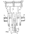
- an internal combustion engine is shown which in this case is a parallel twin engine but the invention could equally be applied to other reciprocating engines.
- the engine includes a pair of pistons 10 movable to reciprocate in cylinders 11 and each piston is pivotally connected to a connecting rod 12 through a bearing 13.
- the other ends of the connecting rods 12 are connected to crankpins 24 on a crankshaft 14 through bearings 15.
- a pair of balancing links 17 and 17 are pivotally attached to the crankshaft 14 through bearings 23, 23 onto a crankpin 18 located between the crankpins 24.
- the crankpin 18 is disposed at 180 0 around a pivot axis 16 of the crankshaft from the crankpins 24.
- the balancing links 17 and 17 are pivotally attached to guide links 19 and 19 respectively by pivots 20 and 20
- the other ends of the guide links 19, 19 are pivotally attached to fixed pivots 21, 21 carried on the engine crankcase 22 so that the guide links extend in opposite directions from one another relative to the links 17 and 17 .
- the guide links 19, 19 are located side by side on the crankpin 18 so that each is able to pivot independently of the other.
- the pivots 20, 20 for the guide links include bearings (not shown) and pivot pins 26, 26 .
- Each guide link 19, 19 has bifurcated arms 27, 27 (Fig. 5) which locate to the sides of the associated balancing link 17, 17 and are apertured to receive the pins 26, 26 .
- the arms 27, 27 accommodate the associated balancing link as the crankshaft rotates and each guide link pivots relative to the associated balancing link.
- the link is also bifurcated to provide arms 28, 28 which pass to either side of lugs 29, 29 on the crankcase 22 and the pivots 21, 21 are in the form of pins passing through the arms 28, 28 and the lugs 29, 29 .
- the pivots 20, 20 by which the guide links 19, 19 are attached to the balancing links 17, 17 are located at the centres of percussion of the balancing links, the term 'centre of percussion being as defined in our prior European application No.
- each balancing link/guide link combination is as described in said prior application.
- the relationship between the connecting rod length and the effective lengths of the balancing links and the guide links is such that: AB is substantially equal to DE BC DC where:
- each balancing link balances one half of the reciprocating mass of the engine and the components of inertia arising in a direction transverse to the movement of the reciprocating mass due to the non linear movement of the balancing link are balanced. Accordingly the lengths of the guide links are no longer material to the balancing action obtained and relatively shorter guide links can be used. In this way the balancing arrangement occupies less apace in the engine configuration and the guide links can be accommodated in the crankcase without providing an extended crankcase profile.
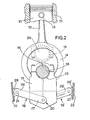
- Figs. 2 and 3 there are shown two positions adopted by the balancing link 17 during operation of the engine.
- Fig. 2 the pistons 10 are at the top of their strokes in the cylinders 11 (top dead centre position) and the balancing links are in their lowermost position.
- the pivotal axes of the pistons 10 to connecting rods 12, the crankpins 24 and the crankpins 18 are in alignment and aligned with the crankshaft axis 16. The same applies when the pistons 10 are at the bottom of their strokes (bottom dead centre position) except that the position of the crankpins 24 and 18 are reversed relative to the axis 16.
- crankpin 18 is displaced to the side of the plane in which the crankshaft axis and the piston lies and the connections 20, 20 of the guide links 19, 19 to the balancing links 17, 17 are displaced equal amounts to opposite sides of . said plane.
- the balancing links are displaced from the vertical in opposite directions in equal amounts thereby balancing the inertia components of the links 17 and 17 .
Landscapes
- Engineering & Computer Science (AREA)
- General Engineering & Computer Science (AREA)
- Mechanical Engineering (AREA)
- Chemical & Material Sciences (AREA)
- Combustion & Propulsion (AREA)
- Physics & Mathematics (AREA)
- Acoustics & Sound (AREA)
- Aviation & Aerospace Engineering (AREA)
- Shafts, Cranks, Connecting Bars, And Related Bearings (AREA)
- Transmission Devices (AREA)
- Lubrication Of Internal Combustion Engines (AREA)
- Valve Device For Special Equipments (AREA)
Applications Claiming Priority (2)
| Application Number | Priority Date | Filing Date | Title |
|---|---|---|---|
| GB8131076 | 1981-10-15 | ||
| GB8131076 | 1981-10-15 |
Publications (2)
| Publication Number | Publication Date |
|---|---|
| EP0077634A1 true EP0077634A1 (fr) | 1983-04-27 |
| EP0077634B1 EP0077634B1 (fr) | 1986-08-20 |
Family
ID=10525166
Family Applications (1)
| Application Number | Title | Priority Date | Filing Date |
|---|---|---|---|
| EP82305435A Expired EP0077634B1 (fr) | 1981-10-15 | 1982-10-13 | Moyens pour réduire les vibrations de moteurs alternatifs |
Country Status (5)
| Country | Link |
|---|---|
| US (1) | US4481918A (fr) |
| EP (1) | EP0077634B1 (fr) |
| JP (1) | JPS58118350A (fr) |
| AU (1) | AU553590B2 (fr) |
| DE (1) | DE3272745D1 (fr) |
Cited By (7)
| Publication number | Priority date | Publication date | Assignee | Title |
|---|---|---|---|---|
| EP0455988A1 (fr) * | 1990-05-09 | 1991-11-13 | Bruderer Ag | Dispositif pour l'équilibrage des forces inertielles dans une machine à poinçonner |
| GB2311820A (en) * | 1996-04-02 | 1997-10-08 | Patrick Michael Cransto Walker | Engine balancing arrangement |
| WO1997037151A3 (fr) * | 1996-04-02 | 1997-12-31 | Patrick Michael Cransto Walker | Systeme de vilebrequin et de piston |
| US6874458B2 (en) | 2001-12-28 | 2005-04-05 | Kohler Co. | Balance system for single cylinder engine |
| US7040273B2 (en) | 2003-04-28 | 2006-05-09 | Brp-Rotax Gmbh & Co. Kg | Mass balancing for internal combustion engine |
| CN103348162A (zh) * | 2011-01-21 | 2013-10-09 | 梅塔电机和能源技术有限公司 | 用于减小活塞式内燃机的曲轴的转动不均衡性的装置 |
| CN106499438A (zh) * | 2015-09-06 | 2017-03-15 | 上海汽车集团股份有限公司 | 活塞运动系统 |
Families Citing this family (9)
| Publication number | Priority date | Publication date | Assignee | Title |
|---|---|---|---|---|
| US4924727A (en) * | 1987-09-09 | 1990-05-15 | Gerber Garment Technologies, Inc. | Cutting machine having balanced reciprocating cutter drive mechanism |
| US4819593A (en) * | 1988-04-28 | 1989-04-11 | Briggs & Stratton Corporation | Pivoting balancer system |
| US5927242A (en) * | 1997-03-25 | 1999-07-27 | Brunswick Corporation | Marine engine with reciprocating force balancer |
| US6202537B1 (en) | 1999-07-13 | 2001-03-20 | Caterpillar Inc. | Connecting rod for horizontally opposed compressor |
| JP3942508B2 (ja) * | 2002-07-30 | 2007-07-11 | 株式会社クボタ | 作業車のエンジン搭載構造 |
| DE102007025549B4 (de) * | 2007-05-31 | 2010-01-14 | Meta Motoren- Und Energie-Technik Gmbh | Verfahren und Vorrichtung zum Vermindern von Drehungleichförmigkeiten der Kurbelwelle einer Kolbenbrennkraftmaschine |
| DE102010007235A1 (de) | 2010-02-09 | 2011-08-11 | Meta Motoren- und Energietechnik GmbH, 52134 | Verfahren zum Verändern der Dauer eines Förderhubs eines Pumpelements sowie Pumpeinrichtung |
| JP7359722B2 (ja) * | 2020-02-28 | 2023-10-11 | ダイハツ工業株式会社 | 2気筒内燃機関 |
| CN116557137B (zh) * | 2023-04-13 | 2025-08-19 | 苏州万龙电动车辆有限公司 | 一种双缸机结构及具有其的往复式直列平行轴内燃机 |
Citations (9)
| Publication number | Priority date | Publication date | Assignee | Title |
|---|---|---|---|---|
| GB909435A (fr) * | 1960-08-18 | |||
| FR319525A (fr) * | 1902-03-12 | 1902-11-14 | De Dion | Moteur à explosions |
| US1794715A (en) * | 1931-03-03 | Boxtbhe development co | ||
| FR840855A (fr) * | 1937-07-21 | 1939-05-05 | Bolinder Munktell | Perfectionnements aux machines à piston et à vilebrequin |
| GB1141189A (en) * | 1967-09-06 | 1969-01-29 | Briggs & Stratton Corp | Counterbalance for single cylinder engines and similar machines |
| GB1242259A (en) * | 1968-12-13 | 1971-08-11 | Birmingham Small Arms Co Ltd | Improvements in or relating to compacting machines |
| DE2423134A1 (de) * | 1974-05-13 | 1975-11-27 | Volkswagenwerk Ag | Massenausgleichseinrichtung |
| DE3040686A1 (de) * | 1980-10-29 | 1982-05-27 | Volkswagenwerk Ag, 3180 Wolfsburg | Massenausgleichseinrichtung |
| EP0058785A1 (fr) * | 1981-02-19 | 1982-09-01 | Triumph Motorcycles (Meriden) Limited | Moyens pour réduire les vibrations dans les moteurs alternatifs |
Family Cites Families (2)
| Publication number | Priority date | Publication date | Assignee | Title |
|---|---|---|---|---|
| US1310090A (en) * | 1919-07-15 | Eahph kdcakdo | ||
| US1091389A (en) * | 1912-12-20 | 1914-03-24 | Harvey L Reese | Internal-combustion engine. |
-
1982
- 1982-09-24 US US06/422,681 patent/US4481918A/en not_active Expired - Fee Related
- 1982-10-13 JP JP57178574A patent/JPS58118350A/ja active Pending
- 1982-10-13 AU AU89333/82A patent/AU553590B2/en not_active Ceased
- 1982-10-13 DE DE8282305435T patent/DE3272745D1/de not_active Expired
- 1982-10-13 EP EP82305435A patent/EP0077634B1/fr not_active Expired
Patent Citations (9)
| Publication number | Priority date | Publication date | Assignee | Title |
|---|---|---|---|---|
| US1794715A (en) * | 1931-03-03 | Boxtbhe development co | ||
| FR319525A (fr) * | 1902-03-12 | 1902-11-14 | De Dion | Moteur à explosions |
| FR840855A (fr) * | 1937-07-21 | 1939-05-05 | Bolinder Munktell | Perfectionnements aux machines à piston et à vilebrequin |
| GB909435A (fr) * | 1960-08-18 | |||
| GB1141189A (en) * | 1967-09-06 | 1969-01-29 | Briggs & Stratton Corp | Counterbalance for single cylinder engines and similar machines |
| GB1242259A (en) * | 1968-12-13 | 1971-08-11 | Birmingham Small Arms Co Ltd | Improvements in or relating to compacting machines |
| DE2423134A1 (de) * | 1974-05-13 | 1975-11-27 | Volkswagenwerk Ag | Massenausgleichseinrichtung |
| DE3040686A1 (de) * | 1980-10-29 | 1982-05-27 | Volkswagenwerk Ag, 3180 Wolfsburg | Massenausgleichseinrichtung |
| EP0058785A1 (fr) * | 1981-02-19 | 1982-09-01 | Triumph Motorcycles (Meriden) Limited | Moyens pour réduire les vibrations dans les moteurs alternatifs |
Cited By (11)
| Publication number | Priority date | Publication date | Assignee | Title |
|---|---|---|---|---|
| EP0455988A1 (fr) * | 1990-05-09 | 1991-11-13 | Bruderer Ag | Dispositif pour l'équilibrage des forces inertielles dans une machine à poinçonner |
| US5138922A (en) * | 1990-05-09 | 1992-08-18 | Bruderer Ag | Apparatus for balancing the mass forces of a punch press |
| GB2311820A (en) * | 1996-04-02 | 1997-10-08 | Patrick Michael Cransto Walker | Engine balancing arrangement |
| WO1997037151A3 (fr) * | 1996-04-02 | 1997-12-31 | Patrick Michael Cransto Walker | Systeme de vilebrequin et de piston |
| GB2311820B (en) * | 1996-04-02 | 2000-03-15 | Patrick Michael Cransto Walker | Crankshaft and piston arrangement |
| US6874458B2 (en) | 2001-12-28 | 2005-04-05 | Kohler Co. | Balance system for single cylinder engine |
| US7040273B2 (en) | 2003-04-28 | 2006-05-09 | Brp-Rotax Gmbh & Co. Kg | Mass balancing for internal combustion engine |
| EP1731732A3 (fr) * | 2003-04-28 | 2007-03-07 | BRP-Rotax GmbH & Co. KG | Balancement des masses pour un moteur à combustion interne |
| CN103348162A (zh) * | 2011-01-21 | 2013-10-09 | 梅塔电机和能源技术有限公司 | 用于减小活塞式内燃机的曲轴的转动不均衡性的装置 |
| CN103348162B (zh) * | 2011-01-21 | 2016-03-16 | 梅塔电机和能源技术有限公司 | 用于减小活塞式内燃机的曲轴的转动不均衡性的装置 |
| CN106499438A (zh) * | 2015-09-06 | 2017-03-15 | 上海汽车集团股份有限公司 | 活塞运动系统 |
Also Published As
| Publication number | Publication date |
|---|---|
| AU553590B2 (en) | 1986-07-24 |
| AU8933382A (en) | 1983-04-21 |
| DE3272745D1 (en) | 1986-09-25 |
| EP0077634B1 (fr) | 1986-08-20 |
| JPS58118350A (ja) | 1983-07-14 |
| US4481918A (en) | 1984-11-13 |
Similar Documents
| Publication | Publication Date | Title |
|---|---|---|
| EP0077634A1 (fr) | Moyens pour réduire les vibrations de moteurs alternatifs | |
| CN102971506B (zh) | 具有多铰链曲柄传动机构和多铰链曲柄传动机构的铰接连杆上的用于缓冲自由惯性力的附加质量的内燃机 | |
| JPS57195944A (en) | Balancer device of internal combustion engine | |
| EP0026633A1 (fr) | Machine à pistons opposés | |
| GB1141189A (en) | Counterbalance for single cylinder engines and similar machines | |
| EP0132943A1 (fr) | Balancier pour moteur à six cylindres disposés en V, à 90 degrés | |
| EP1731732B1 (fr) | Balancement des masses pour un moteur à combustion interne | |
| US3112658A (en) | Harmonic balancing device for internal combustion engines | |
| US4694785A (en) | Piston apparatus | |
| US4351202A (en) | Engine | |
| KR20000005181A (ko) | 크랭크샤프트와 피스톤장치 | |
| US4926810A (en) | Engine vibration balancer | |
| EP2211073B1 (fr) | Procédé pour réduire les vibrations faisant appel au contrepoids à mouvement alternatif | |
| EP0058785A1 (fr) | Moyens pour réduire les vibrations dans les moteurs alternatifs | |
| CA2433166A1 (fr) | Machine a mouvement alternatif | |
| US4470387A (en) | Mass balancing arrangement for a reciprocating-piston engine | |
| US20040123817A1 (en) | Opposed internal combustion engine | |
| GB2057061A (en) | Means for reducing vibration in reciprocating engines | |
| JPS6256645A (ja) | エンジンのクランクバランス装置 | |
| KR100222822B1 (ko) | V형 6기통 엔진 크랭크 샤프트의 관성 우력 저감장치 | |
| SU1776898A1 (ru) | Дbигateль bhуtpehheгo cгopahия | |
| EP0245583A2 (fr) | Système de compensation du balourd à poids aligné pour moteur à cylindre unique | |
| DE3137933A1 (de) | Anordnung zum massenausgleich bei einer hubkolben-kurbelwellmaschine | |
| GB2058223A (en) | Balancing device for reciprocating machine | |
| EP3805599B1 (fr) | Système d'équilibrage de moteur |
Legal Events
| Date | Code | Title | Description |
|---|---|---|---|
| PUAI | Public reference made under article 153(3) epc to a published international application that has entered the european phase |
Free format text: ORIGINAL CODE: 0009012 |
|
| AK | Designated contracting states |
Designated state(s): DE FR GB IT |
|
| 17P | Request for examination filed |
Effective date: 19830414 |
|
| GRAA | (expected) grant |
Free format text: ORIGINAL CODE: 0009210 |
|
| RAP1 | Party data changed (applicant data changed or rights of an application transferred) |
Owner name: MORTON, PAUL GERVILLE |
|
| RIN1 | Information on inventor provided before grant (corrected) |
Inventor name: MORTON, PAUL GERVILLE |
|
| AK | Designated contracting states |
Kind code of ref document: B1 Designated state(s): DE FR GB IT |
|
| RAP2 | Party data changed (patent owner data changed or rights of a patent transferred) |
Owner name: MORTON, PAUL GREVILLE |
|
| REF | Corresponds to: |
Ref document number: 3272745 Country of ref document: DE Date of ref document: 19860925 |
|
| ET | Fr: translation filed | ||
| ITF | It: translation for a ep patent filed | ||
| PLBE | No opposition filed within time limit |
Free format text: ORIGINAL CODE: 0009261 |
|
| STAA | Information on the status of an ep patent application or granted ep patent |
Free format text: STATUS: NO OPPOSITION FILED WITHIN TIME LIMIT |
|
| 26N | No opposition filed | ||
| PGFP | Annual fee paid to national office [announced via postgrant information from national office to epo] |
Ref country code: GB Payment date: 19890930 Year of fee payment: 8 |
|
| PGFP | Annual fee paid to national office [announced via postgrant information from national office to epo] |
Ref country code: FR Payment date: 19891010 Year of fee payment: 8 |
|
| ITTA | It: last paid annual fee | ||
| PGFP | Annual fee paid to national office [announced via postgrant information from national office to epo] |
Ref country code: DE Payment date: 19891130 Year of fee payment: 8 |
|
| PG25 | Lapsed in a contracting state [announced via postgrant information from national office to epo] |
Ref country code: GB Effective date: 19901013 |
|
| GBPC | Gb: european patent ceased through non-payment of renewal fee | ||
| PG25 | Lapsed in a contracting state [announced via postgrant information from national office to epo] |
Ref country code: FR Effective date: 19910628 |
|
| PG25 | Lapsed in a contracting state [announced via postgrant information from national office to epo] |
Ref country code: DE Effective date: 19910702 |
|
| REG | Reference to a national code |
Ref country code: FR Ref legal event code: ST |