EP0077663B1 - Intramedullary pin cutting instrument - Google Patents
Intramedullary pin cutting instrument Download PDFInfo
- Publication number
- EP0077663B1 EP0077663B1 EP82305506A EP82305506A EP0077663B1 EP 0077663 B1 EP0077663 B1 EP 0077663B1 EP 82305506 A EP82305506 A EP 82305506A EP 82305506 A EP82305506 A EP 82305506A EP 0077663 B1 EP0077663 B1 EP 0077663B1
- Authority
- EP
- European Patent Office
- Prior art keywords
- reduced diameter
- diameter portion
- piston
- anvil
- bore
- Prior art date
- Legal status (The legal status is an assumption and is not a legal conclusion. Google has not performed a legal analysis and makes no representation as to the accuracy of the status listed.)
- Expired
Links
- 238000005520 cutting process Methods 0.000 title claims description 63
- 239000012530 fluid Substances 0.000 claims description 11
- 238000001356 surgical procedure Methods 0.000 claims description 10
- 230000000295 complement effect Effects 0.000 claims description 4
- 229910052751 metal Inorganic materials 0.000 claims description 4
- 239000002184 metal Substances 0.000 claims description 4
- 230000000399 orthopedic effect Effects 0.000 claims description 4
- 230000004044 response Effects 0.000 claims description 3
- 210000000988 bone and bone Anatomy 0.000 description 11
- 238000010008 shearing Methods 0.000 description 6
- 230000008901 benefit Effects 0.000 description 5
- 239000000463 material Substances 0.000 description 5
- 238000000034 method Methods 0.000 description 4
- 239000010935 stainless steel Substances 0.000 description 4
- 229910001220 stainless steel Inorganic materials 0.000 description 4
- 230000009471 action Effects 0.000 description 3
- 230000007246 mechanism Effects 0.000 description 3
- 208000010392 Bone Fractures Diseases 0.000 description 2
- 229910000967 As alloy Inorganic materials 0.000 description 1
- 229910001209 Low-carbon steel Inorganic materials 0.000 description 1
- 229910000831 Steel Inorganic materials 0.000 description 1
- 229910001315 Tool steel Inorganic materials 0.000 description 1
- 230000002411 adverse Effects 0.000 description 1
- 229910052782 aluminium Inorganic materials 0.000 description 1
- XAGFODPZIPBFFR-UHFFFAOYSA-N aluminium Chemical compound [Al] XAGFODPZIPBFFR-UHFFFAOYSA-N 0.000 description 1
- 238000004891 communication Methods 0.000 description 1
- 230000006835 compression Effects 0.000 description 1
- 238000007906 compression Methods 0.000 description 1
- 230000001419 dependent effect Effects 0.000 description 1
- 239000000645 desinfectant Substances 0.000 description 1
- 239000003814 drug Substances 0.000 description 1
- 230000000694 effects Effects 0.000 description 1
- 231100001261 hazardous Toxicity 0.000 description 1
- 238000003780 insertion Methods 0.000 description 1
- 230000037431 insertion Effects 0.000 description 1
- 239000007788 liquid Substances 0.000 description 1
- 230000008439 repair process Effects 0.000 description 1
- 230000000717 retained effect Effects 0.000 description 1
- 238000007789 sealing Methods 0.000 description 1
- 239000010959 steel Substances 0.000 description 1
Images
Classifications
-
- A—HUMAN NECESSITIES
- A61—MEDICAL OR VETERINARY SCIENCE; HYGIENE
- A61B—DIAGNOSIS; SURGERY; IDENTIFICATION
- A61B17/00—Surgical instruments, devices or methods
- A61B17/56—Surgical instruments or methods for treatment of bones or joints; Devices specially adapted therefor
- A61B17/58—Surgical instruments or methods for treatment of bones or joints; Devices specially adapted therefor for osteosynthesis, e.g. bone plates, screws or setting implements
- A61B17/88—Osteosynthesis instruments; Methods or means for implanting or extracting internal or external fixation devices
- A61B17/8863—Apparatus for shaping or cutting osteosynthesis equipment by medical personnel
Definitions
- the present invention relates to a hand-held instrument for use in orthopedic surgical procedures for cutting a relatively hard metal intramedullary pin and comprising an elongate, substantially cylindrical housing accommodating a hydraulically actuated piston which carries a first part of a cutting means for severing said pin, and has a transverse hole in said housing for receiving the pin to be cut.
- intramedullary pins and the like are preferably formed of stainless steel, the procedure for cutting the pin after it has been inserted in the bone becomes difficult due to the strength and hardness of the pin material.
- various tools such as saws and pivoting jaw type cutters have been used to cut intramedullary pins to the required length both before and during the surgical procedure. The use of these devices has been generally unsatisfactory in that they are cumbersome and difficult to manipulate properly.
- an instrument of a type particularly adapted for cutting intramedullary pins wherein the cutting operation may be performed before as well as after the pin has been inserted into the medullary cavity or the like. It is particularly desirable that the instrument be as compact and as easily handled as possible in the vicinity of the operating table by the person performing the surgery. It is also important that the instrument be applied to cut the pin without exerting any substantial forces on the portion of the pin already inserted into the bone so as to avoid further damage to the bone or other areas of the patient's body. Furthermore, the hardness of stainless steel intramedullary pins requires that an instrument be used which is capable of exerting substantial cutting forces without requiring an operating force greater than that which the average person using the instrument may easily exert.
- the present invention is characterized in that the housing includes a first housing section having a first bore defining at least in part a first pressure fluid chamber, a first substantially uniform reduced diameter portion of said housing extending coaxially from said first housing section and having a distal end, said first reduced diameter portion including a second bore coaxial with and opening into said first bore, said transverse hole being formed in said first reduced diameter portion near said distal end and intersecting said second bore; said hydraulically actuated piston is disposed in said first bore; and in that said instrument further comprises an anvil mounted at said distal end adjacent to said transverse hole and serving as the second part of the cutting means; as the first part of the cutting means a rod member slidably disposed in said second bore and connected at one end to said hydraulically actuated piston, said rod member including a transverse cutting edge on a- distal end of said rod member opposite said one end, and being movable toward said anvil in response to pressure fluid acting on said hydraulically actuated piston to cut the pin disposed in said transverse hole and against said
- a second piston slidably disposed in said third bore and movable toward and away from said first piston to displace a quantity of pressure fluid in said chambers, to urge said first piston and said rod member toward said anvil, or to permit said hydraulically actuated piston and said rod member to move away from said anvil, respectively;
- a screw actuator member threadedly engaged with cooperating threads formed inside said second reduced diameter portion of said housing, and including a first end portion extending into said third bore; thrust bearing means in said third bore interposed between said first end portion of said screw actuator member and said second piston to prevent rotation of the piston; a second end portion of said screw actuator member projecting from a distal end of said second reduced diameter portion of said housing, and means on said second end portion of said screw actuator member for rotating said screw actuator member to move said second piston toward said first piston and a handle member projecting from said second reduced diameter portion of said housing substantially normal to the axis of rotation of said screw actuator member to hold said instrument against rotation during rotation of said screw actuator member.
- the pin cutting instrument of the present invention thus employs a combination of force transmitting mechanisms to provide a substantial cutting force required for intramedullary stainless steel pins, which mechanisms require only a moderate input force but are capable of providing a substantial mechanical advantage to develop a very high cutting force for shearing the pin between two cutting edges.
- a substantial mechanical advantage is derived through the screw actuator and due to the differential areas of the respective pistons so that a suitable shearing force is applied to the cutting edges with only a moderate turning force on the screw.
- the reaction moment imposed on the instrument due to rotation of the actuating screw may be counteracted to substantially reduce any reaction forces imposed on the pin being cut.
- the instrument provides a pair of opposed cutting edges which may be easily repaired or replaced, as required, if they should become dull or broken. Moreover, one of the cutting edges is formed on a member which may be easily adjusted to conform to the shear plane of the other cutting edge so that a uniform and complete cutting action is imposed on the pin.
- the instrument 10 includes a housing 12 comprising a first generally cylindrical section 13 having an elongated reduced diameter portion 14.
- the housing 12 includes a second section 15 which may have a cylindrical exterior shape or be formed in a hexagonal shape, as illustrated.
- the housing section 15 also includes a reduced diameter nose portion 16.
- the housing sections 13 and 15 are threadedly engaged with each other by respective internal and external threaded portions 17 and 18.
- the housing sections 13 and 15 When the housing sections 13 and 15 are threadedly engaged they form a cylindrical chamber 19 for a purpose to be described in further detail herein.
- the distal end 20 of the cylindrical threaded portion 18 is engageable with a resilient gasket 21 disposed against a transverse wall 22 of the housing section 13.
- the chamber 19 is in direct communication with a further cylindrical chamber portion 23 formed by an elongated bore 25 within the reduced diameter portion 14 of the housing section 13.
- the bore 25 is closed at one end by a transverse wall portion 24 having an internally threaded bore 26.
- the instrument 10 is provided with actuating mechanism including an elongated screw actuator 28 having threads complementary to the threads formed in the bore 26 whereby the screw actuator may be extended into the bore 25 for actuating a piston 30 slidably disposed within the bore 25 and delimiting the chamber 23.
- the portion of the screw actuator 28 extending out of the housing section 14 includes a hexagonal shaped head 32 which may be provided with a transverse bore 33 for receiving a turning handle or the like, not shown.
- the actuating screw 28 may be rotated by engaging the hexagonal head portion 32 with a wrench, also not shown.
- the piston 30 is provided with suitable annular seals for engaging the bore 25 in sealing relationship thereto, which seals may comprise conventional o-rings 34, for example.
- a thrust bearing assembly is interposed between the face 38 of the piston and the end of the screw 28.
- the thrust bearing preferably includes spaced apart thrust washers 40 between which is disposed a bearing retainer 42 supporting a plurality of bearing balls or rollers.
- a distal end portion 44 of the screw 28 is provided with a somewhat spherical shape and projects into the interior of one of the races or washers 40 to help maintain the bearing centered against the piston face 38.
- the cutting instrument 10 includes a second piston 48 slidably disposed within a bore 50 formed within the housing section 15 and defining in part the chamber 19.
- the piston 48 is also provided with suitable seals for engaging the walls of the bore 50 comprising conventional o-rings 52.
- the piston 48 is removably connected to an elongated cylindrical member 54 disposed within a bore 56 formed in the nose portion 16 of the housing section 15.
- the member 54 is provided with a threaded portion 58 which extends into a complementary threaded hole 60 formed in the piston 48.
- the member 54 is further secured to the piston by a locknut 62.
- a helical coil type compression spring 64 is disposed around the member 54 and the locknut 62 and interposed between one face of the piston 48 and a transverse wall 66 formed within the housing section 15.
- the end of the member 54 opposite the threaded portion 58 is provided with an axially projecting portion forming a cutting edge 68.
- the cutting edge 68 is cooperable with a complementary cutting edge 70 formed on an anvil member 72 to provide for shearing an element which may be interposed between the members 54 and 72 and within a transverse bore 74 formed in the housing portion 16.
- the anvil 72 comprises an externally threaded member which is engaged with an internal threaded portion 73 formed in the end of the housing portion 16.
- the anvil member 72 is secured in a desired position to be cooperable with the member 54 by a locknut 80.
- a removable cap 77 is threadedly engaged with the end of the housing portion 16 and covers the end of the anvil member 72 and the locknut 80 to minimize the chance of unwanted loosening of the nut and to provide a smooth exterior surface at the end of the housing portion.
- the member 54 is provided with an elongated keyslot 55 into which a guidepin 57 projects to prevent rotation of the member 54 which would result in misalignment of the cutting edges 68 and 70.
- the guidepin 57 is preferably formed as a socket head type screw which may have a prevailing torque type thread or thread insert so that the screw will be suitably retained in a set position in the housing portion 16 without forcibly engaging the bottom of the keyslot 55.
- the members 54 and 72 may be formed of suitable hardenable tool steel or the like so that the cutting edges 68 and 70 may be hardened and ground to provide cutting edges which will withstand shearing forces exerted on stainless steel pin material and the like.
- the cutting edge 68 is formed by a substantially planar surface 69 parallel to the longitudinal axis of the member 54 and by a substantially transverse edge 71 provided with suitable rake to form an included angle for the cutting edge 68 in accordance with metal cutting practices.
- the cutting edge 70 is formed by a planar surface 75 which is proportioned to be disposed closely adjacent to the surface 69.
- the cutting edge 70 also has a suitable included angle defined in part by a transverse surface 79.
- the end portion 14 of the housing section 13 is provided with suitable tapped holes 90 and 91 spaced approximately 90° apart and extending transversely with respect to the longitudinal axis of the instrument 10.
- a handle member 92 including a threaded end portion 93, is removably disposed in the tapped hole 90 and may be alternately disposed in the tapped hole 91 whereby the handle may be conveniently located for enhanced manipulation of the instrument 10.
- the reduced diameter housing portion 14 includes a removable plug 94 whereby the chambers 19 and 23 may be filled with a suitable hydraulic fluid for actuating the piston 48 in response to movement of the piston 30 under the urging of the screw actuator 28.
- the material strength requirements for intramedullary pins and the like are such that substantial cutting forces must be exerted in order to cut a pin in the range of .18 to .25 inches (4.6 to 6.35 mm) in diameter, which is a typical diameter range for intramedullary pins used in orthopedic surgery. Accordingly, a substantial axial force must be applied to the member 54 to provide a shearing action for severing a pin such as the pin 96, shown disposed in the bore 74 in Figure 1. Moreover, it is important that, when cutting a pin that has already been inserted into the medullary cavity, minimal forces be applied to the pin lest further damage to the patient be incurred during the surgical procedure.
- the instrument 10 provides for exerting a substantial and adequate cutting force for such types of pins without imposing any substantial force on the pin itself after it has already been inserted into a bone.
- the combination of the screw actuator 28 and the hydraulic actuator comprising the pistons 30 and 48 disposed in the respective chambers 23 and 19 provides for a substantial axial force to be imposed on the member 54 to shear a pin along a transverse plane while only a nominal turning effort on the screw need be applied.
- the provision of the laterally extending handle 92 provides for improved handling of the instrument 10, as well as counteracting the turning effort imposed on the screw actuator 28, so that a minimal lateral reaction force is imposed on the pin itself.
- the operation of the instrument 10 to cut a pin such as the pin 96 is believed to be readily understandable from the foregoing description but a concise explanation will be provided herein.
- the normal position of the elements of the instrument 10 prior to cutting a pin would be substantially as shown in Figure 2.
- the member 72 would be adjusted such that the cutting edge 70 would be in parallel alignment with the cutting edge 68.
- the member 72 would also be adjusted such that the transverse face 79 would be approximately aligned with an edge of the bore 74.
- the bore 74 is, of course, of sufficient diameter to allow a pin to be inserted past the cutting edge 70 when the member 72 is adjusted as described.
- the screw actuator 28 When the instrument is in the relaxed position, the screw actuator 28 is retracted out of the housing section 14 far enough so that the spring 64 may push the piston 48 toward the wall 22 sufficiently that the cutting edge 68 does not extend into the bore 74.
- the pin When it is desired to apply the instrument to cut a pin, the pin is inserted into the bore 74 and the screw actuator 28 is rotated to move the piston 30 downward, viewing Figure 2. Fluid is displaced by the piston 30 from chamber 23 into the chamber 19 urging the piston 48 and member 54 toward the anvil 72.
- the screw actuator 28 When a pin is severed by the shearing action of the cooperating cutting edges 68 and 70, the screw actuator 28 is rotated in the opposite direction and the spring 64 effects retraction of the pistons 48 and 30 to the respective positions shown in Figure 2.
- a force exerted on the piston 30 is increased in proportion to the ratio of the transverse face areas of the pistons 48 and 30.
- the axial force exerted by the screw actuator 28 is increased substantially over the actual force exerted on the head portion 32 or on a lever attached to the head portion.
- the force exerted to rotate the screw actuator 28 will depend on the radius of the lever arm connected to the head 32.
- the mechanical advantage gained through rotation of the screw actuator 28 is also dependent on the pitch of the screw threads. It has been determined in accordance with the present invention that a screw actuator having nominal thread size of .625 inch (15.9 mm) diameter and 18 threads per inch (709 threads per metre) UNF provides a suitable force multiplication in combination with pistons 30 and 48 having nominal diameters of one inch (25.4 mm) and two inches (50.8 mm), respectively.
- the compactness of the instrument 10 is a particularly attractive feature in regard to the requirements for handling the instrument in conjunction with surgical procedures.
- the reduced diameter section of the housing 16 permits placing the instrument closely adjacent to the portion of the bone from which the intramedullary pin extends so that the pin may be cut at the desired point.
- the provision of the handle 92 aids in counteracting the torque exerted on the screw actuator 28 to minimize reaction forces exerted on the pin, particularly when the pin is already inserted into the medullary cavity.
- the instrument 10 also includes the attractive features of replaceable cutting edges which may be easily replaced by interchanging the anvil member 72 and the cutting edge member 54 with replacement parts. Moreover, the member 54 and the anvil 72 may be easily removed from the instrument for sharpening the respective cutting edges 68 and 70.
- the instrument 10 may be constructed of conventional materials used for manual and power tools.
- the housing sections 13 and 15 as well as the handle member 92 may be made of aluminum, for example.
- the pistons 30 and 48 and the screw actuator 28 are preferably made of conventional engineering materials such as alloy or low carbon steel.
- the instrument 10 can be completely sterilized using liquid or gas disinfectants as well as heat without adversely affecting the instrument components.
- the instrument 10 has been adapted particularly for cutting intramedullary pins but the instrument could also be advantageously used for other pin cutting applications.
Landscapes
- Health & Medical Sciences (AREA)
- Life Sciences & Earth Sciences (AREA)
- Orthopedic Medicine & Surgery (AREA)
- Surgery (AREA)
- Biomedical Technology (AREA)
- Engineering & Computer Science (AREA)
- Nuclear Medicine, Radiotherapy & Molecular Imaging (AREA)
- Heart & Thoracic Surgery (AREA)
- Medical Informatics (AREA)
- Molecular Biology (AREA)
- Animal Behavior & Ethology (AREA)
- General Health & Medical Sciences (AREA)
- Public Health (AREA)
- Veterinary Medicine (AREA)
- Surgical Instruments (AREA)
Description
- The present invention relates to a hand-held instrument for use in orthopedic surgical procedures for cutting a relatively hard metal intramedullary pin and comprising an elongate, substantially cylindrical housing accommodating a hydraulically actuated piston which carries a first part of a cutting means for severing said pin, and has a transverse hole in said housing for receiving the pin to be cut.
- In the performance of orthopedic surgery in both human and veterinary medicine, it is known to provide for repairing fractured bones by inserting steel pins of various cross-sectional shapes in the medullary cavity of the bone to support the bone sections on opposite sides of the fracture. Since the repair of some bone fractures requires the insertion of intramedullary support pins of varying lengths, it may be necessary to cut the pin during the surgical procedure once the required length of the pin has been determined. Quite often in the performance of a surgical procedure, a pin of more than sufficient length is inserted into the medullary cavity and then cut to the desired length prior to completion of the procedure.
- Since intramedullary pins and the like are preferably formed of stainless steel, the procedure for cutting the pin after it has been inserted in the bone becomes difficult due to the strength and hardness of the pin material. Heretofore, various tools such as saws and pivoting jaw type cutters have been used to cut intramedullary pins to the required length both before and during the surgical procedure. The use of these devices has been generally unsatisfactory in that they are cumbersome and difficult to manipulate properly. Known techniques for cutting intramedullary pins, particularly when they have already been inserted into the bone, are generally unsatisfactory since it is usually required that the bone and associated portion of the patient's body be carefully maintained in a particular position without any forces exerted thereon during the procedure to avoid further damage to the fractured bone or other parts of the patient's body.
- Accordingly, there has been a serious need for an instrument of a type particularly adapted for cutting intramedullary pins wherein the cutting operation may be performed before as well as after the pin has been inserted into the medullary cavity or the like. It is particularly desirable that the instrument be as compact and as easily handled as possible in the vicinity of the operating table by the person performing the surgery. It is also important that the instrument be applied to cut the pin without exerting any substantial forces on the portion of the pin already inserted into the bone so as to avoid further damage to the bone or other areas of the patient's body. Furthermore, the hardness of stainless steel intramedullary pins requires that an instrument be used which is capable of exerting substantial cutting forces without requiring an operating force greater than that which the average person using the instrument may easily exert.
- It has been further determined that it is often desirable in the environment of a surgical operating room to provide instruments which may be suitably manually actuated thereby eliminating the need for instruments requiring electrical or other sources of power which can be hazardous as well as inconvenient to use.
- An instrument of the type described in the first paragraph of this specification is described in French Patent Specification FR-A-2336910. In that specification the first part of the cutting means is a rod fitting within the housing and also having a transverse hole for the passage of the pin, which is then cut by relative axial movement of the rod and the cylinder. This instrument fails to meet the requirement for an instrument which is adapted to provide a sufficient cutting force to shear relatively hard metal pins but which may be easily manually actuated without imposing unwanted forces on the pin after it has been already inserted into the medullary cavity.
- The present invention is characterized in that the housing includes a first housing section having a first bore defining at least in part a first pressure fluid chamber, a first substantially uniform reduced diameter portion of said housing extending coaxially from said first housing section and having a distal end, said first reduced diameter portion including a second bore coaxial with and opening into said first bore, said transverse hole being formed in said first reduced diameter portion near said distal end and intersecting said second bore; said hydraulically actuated piston is disposed in said first bore; and in that said instrument further comprises an anvil mounted at said distal end adjacent to said transverse hole and serving as the second part of the cutting means; as the first part of the cutting means a rod member slidably disposed in said second bore and connected at one end to said hydraulically actuated piston, said rod member including a transverse cutting edge on a- distal end of said rod member opposite said one end, and being movable toward said anvil in response to pressure fluid acting on said hydraulically actuated piston to cut the pin disposed in said transverse hole and against said anvil; a second substantially uniform reduced diameter portion of said housing extending directly from and coaxial with said first housing section and coaxial with said first reduced diameter portion and opposite said first reduced diameter portion, said second reduced diameter portion including a third bore defining at least in part a second pressure fluid chamber opening into said first chamber;. a second piston slidably disposed in said third bore and movable toward and away from said first piston to displace a quantity of pressure fluid in said chambers, to urge said first piston and said rod member toward said anvil, or to permit said hydraulically actuated piston and said rod member to move away from said anvil, respectively; a screw actuator member threadedly engaged with cooperating threads formed inside said second reduced diameter portion of said housing, and including a first end portion extending into said third bore; thrust bearing means in said third bore interposed between said first end portion of said screw actuator member and said second piston to prevent rotation of the piston; a second end portion of said screw actuator member projecting from a distal end of said second reduced diameter portion of said housing, and means on said second end portion of said screw actuator member for rotating said screw actuator member to move said second piston toward said first piston and a handle member projecting from said second reduced diameter portion of said housing substantially normal to the axis of rotation of said screw actuator member to hold said instrument against rotation during rotation of said screw actuator member.
- The pin cutting instrument of the present invention thus employs a combination of force transmitting mechanisms to provide a substantial cutting force required for intramedullary stainless steel pins, which mechanisms require only a moderate input force but are capable of providing a substantial mechanical advantage to develop a very high cutting force for shearing the pin between two cutting edges. A substantial mechanical advantage is derived through the screw actuator and due to the differential areas of the respective pistons so that a suitable shearing force is applied to the cutting edges with only a moderate turning force on the screw.
- By providing an arrangement of an elongated screw actuator and a laterally extending support handle for the instrument housing, the reaction moment imposed on the instrument due to rotation of the actuating screw may be counteracted to substantially reduce any reaction forces imposed on the pin being cut.
- The instrument provides a pair of opposed cutting edges which may be easily repaired or replaced, as required, if they should become dull or broken. Moreover, one of the cutting edges is formed on a member which may be easily adjusted to conform to the shear plane of the other cutting edge so that a uniform and complete cutting action is imposed on the pin.
- Further superior features and advantages of the intramedullary pin cutting instrument of the present invention will be appreciated upon reading the detailed description which follows in conjunction with the drawings.
-
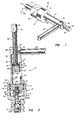
- Figure 1 is a perspective view of the intramedullary pin cutting instrument of the present invention; and
- Figure 2 is a longitudinal central section view of the pin cutting instrument illustrated in Figure 1.
- Referring to the drawing figures, the pin cutting instrument of the present invention is illustrated and generally designated by the
numeral 10. Theinstrument 10 includes ahousing 12 comprising a first generallycylindrical section 13 having an elongated reduceddiameter portion 14. Thehousing 12 includes asecond section 15 which may have a cylindrical exterior shape or be formed in a hexagonal shape, as illustrated. Thehousing section 15 also includes a reduceddiameter nose portion 16. Thehousing sections portions - When the
housing sections cylindrical chamber 19 for a purpose to be described in further detail herein. Thedistal end 20 of the cylindrical threadedportion 18 is engageable with aresilient gasket 21 disposed against atransverse wall 22 of thehousing section 13. Thechamber 19 is in direct communication with a further cylindrical chamber portion 23 formed by anelongated bore 25 within the reduceddiameter portion 14 of thehousing section 13. Thebore 25 is closed at one end by atransverse wall portion 24 having an internally threadedbore 26. - The
instrument 10 is provided with actuating mechanism including anelongated screw actuator 28 having threads complementary to the threads formed in thebore 26 whereby the screw actuator may be extended into thebore 25 for actuating apiston 30 slidably disposed within thebore 25 and delimiting the chamber 23. The portion of thescrew actuator 28 extending out of thehousing section 14 includes a hexagonalshaped head 32 which may be provided with atransverse bore 33 for receiving a turning handle or the like, not shown. Alternatively, the actuatingscrew 28 may be rotated by engaging thehexagonal head portion 32 with a wrench, also not shown. - The
piston 30 is provided with suitable annular seals for engaging thebore 25 in sealing relationship thereto, which seals may comprise conventional o-rings 34, for example. A thrust bearing assembly is interposed between theface 38 of the piston and the end of thescrew 28. The thrust bearing preferably includes spaced apartthrust washers 40 between which is disposed abearing retainer 42 supporting a plurality of bearing balls or rollers. Adistal end portion 44 of thescrew 28 is provided with a somewhat spherical shape and projects into the interior of one of the races orwashers 40 to help maintain the bearing centered against thepiston face 38. By providing the thrust bearing 40, thescrew actuator 28 may be rotated without requiring rotation of thepiston 30 while also suitably reducing the friction forces between theend portion 44 and the piston. - The
cutting instrument 10 includes asecond piston 48 slidably disposed within a bore 50 formed within thehousing section 15 and defining in part thechamber 19. Thepiston 48 is also provided with suitable seals for engaging the walls of the bore 50 comprising conventional o-rings 52. Thepiston 48 is removably connected to an elongatedcylindrical member 54 disposed within abore 56 formed in thenose portion 16 of thehousing section 15. Themember 54 is provided with a threadedportion 58 which extends into a complementary threadedhole 60 formed in thepiston 48. Themember 54 is further secured to the piston by a locknut 62. A helical coiltype compression spring 64 is disposed around themember 54 and thelocknut 62 and interposed between one face of thepiston 48 and atransverse wall 66 formed within thehousing section 15. - The end of the
member 54 opposite the threadedportion 58 is provided with an axially projecting portion forming acutting edge 68. Thecutting edge 68 is cooperable with acomplementary cutting edge 70 formed on ananvil member 72 to provide for shearing an element which may be interposed between themembers transverse bore 74 formed in thehousing portion 16. Theanvil 72 comprises an externally threaded member which is engaged with an internal threadedportion 73 formed in the end of thehousing portion 16. Theanvil member 72 is secured in a desired position to be cooperable with themember 54 by a locknut 80. Aremovable cap 77 is threadedly engaged with the end of thehousing portion 16 and covers the end of theanvil member 72 and the locknut 80 to minimize the chance of unwanted loosening of the nut and to provide a smooth exterior surface at the end of the housing portion. - As illustrated in Figure 2, the
member 54 is provided with anelongated keyslot 55 into which aguidepin 57 projects to prevent rotation of themember 54 which would result in misalignment of thecutting edges guidepin 57 is preferably formed as a socket head type screw which may have a prevailing torque type thread or thread insert so that the screw will be suitably retained in a set position in thehousing portion 16 without forcibly engaging the bottom of thekeyslot 55. - The
members cutting edges cutting edge 68 is formed by a substantiallyplanar surface 69 parallel to the longitudinal axis of themember 54 and by a substantiallytransverse edge 71 provided with suitable rake to form an included angle for thecutting edge 68 in accordance with metal cutting practices. In like manner, thecutting edge 70 is formed by aplanar surface 75 which is proportioned to be disposed closely adjacent to thesurface 69. Thecutting edge 70 also has a suitable included angle defined in part by atransverse surface 79. - The
end portion 14 of thehousing section 13 is provided with suitable tappedholes instrument 10. Ahandle member 92, including a threadedend portion 93, is removably disposed in the tappedhole 90 and may be alternately disposed in the tappedhole 91 whereby the handle may be conveniently located for enhanced manipulation of theinstrument 10. - As illustrated in the drawing figures, the reduced
diameter housing portion 14 includes aremovable plug 94 whereby thechambers 19 and 23 may be filled with a suitable hydraulic fluid for actuating thepiston 48 in response to movement of thepiston 30 under the urging of thescrew actuator 28. - The material strength requirements for intramedullary pins and the like are such that substantial cutting forces must be exerted in order to cut a pin in the range of .18 to .25 inches (4.6 to 6.35 mm) in diameter, which is a typical diameter range for intramedullary pins used in orthopedic surgery. Accordingly, a substantial axial force must be applied to the
member 54 to provide a shearing action for severing a pin such as thepin 96, shown disposed in thebore 74 in Figure 1. Moreover, it is important that, when cutting a pin that has already been inserted into the medullary cavity, minimal forces be applied to the pin lest further damage to the patient be incurred during the surgical procedure. Accordingly, theinstrument 10 provides for exerting a substantial and adequate cutting force for such types of pins without imposing any substantial force on the pin itself after it has already been inserted into a bone. The combination of thescrew actuator 28 and the hydraulic actuator comprising thepistons respective chambers 23 and 19 provides for a substantial axial force to be imposed on themember 54 to shear a pin along a transverse plane while only a nominal turning effort on the screw need be applied. Moreover, the provision of the laterally extendinghandle 92 provides for improved handling of theinstrument 10, as well as counteracting the turning effort imposed on thescrew actuator 28, so that a minimal lateral reaction force is imposed on the pin itself. - The operation of the
instrument 10 to cut a pin such as thepin 96 is believed to be readily understandable from the foregoing description but a concise explanation will be provided herein. The normal position of the elements of theinstrument 10 prior to cutting a pin would be substantially as shown in Figure 2. Themember 72 would be adjusted such that thecutting edge 70 would be in parallel alignment with thecutting edge 68. Themember 72 would also be adjusted such that thetransverse face 79 would be approximately aligned with an edge of thebore 74. Thebore 74 is, of course, of sufficient diameter to allow a pin to be inserted past thecutting edge 70 when themember 72 is adjusted as described. When the instrument is in the relaxed position, thescrew actuator 28 is retracted out of thehousing section 14 far enough so that thespring 64 may push thepiston 48 toward thewall 22 sufficiently that thecutting edge 68 does not extend into thebore 74. When it is desired to apply the instrument to cut a pin, the pin is inserted into thebore 74 and thescrew actuator 28 is rotated to move thepiston 30 downward, viewing Figure 2. Fluid is displaced by thepiston 30 from chamber 23 into thechamber 19 urging thepiston 48 andmember 54 toward theanvil 72. When a pin is severed by the shearing action of the cooperating cuttingedges screw actuator 28 is rotated in the opposite direction and thespring 64 effects retraction of thepistons - Since the fluid pressure in the
chambers 19 and 23 is uniform throughout, a force exerted on thepiston 30 is increased in proportion to the ratio of the transverse face areas of thepistons screw actuator 28 is increased substantially over the actual force exerted on thehead portion 32 or on a lever attached to the head portion. Of course, the force exerted to rotate thescrew actuator 28 will depend on the radius of the lever arm connected to thehead 32. - The mechanical advantage gained through rotation of the
screw actuator 28 is also dependent on the pitch of the screw threads. It has been determined in accordance with the present invention that a screw actuator having nominal thread size of .625 inch (15.9 mm) diameter and 18 threads per inch (709 threads per metre) UNF provides a suitable force multiplication in combination withpistons pistons screw actuator 28, would produce an axial force on thecutting edge member 54 of 9150 Ibs (40.7 kN) neglecting friction in the screw and the pistons. This would be sufficient to shear a rod of .25 inches (6.35 mm) in diameter having a tensile strength of 186,000 lbs. per square inch (1282.3 MPa). Of course, the total torque applied to thescrew actuator 28 may be varied considerably depending on the moment arm of the lever inserted in thebore 33 or another source of torsional effort such as a manual or power wrench applied to thehead 32. - Those skilled in the art will appreciate that the compactness of the
instrument 10 is a particularly attractive feature in regard to the requirements for handling the instrument in conjunction with surgical procedures. The reduced diameter section of thehousing 16 permits placing the instrument closely adjacent to the portion of the bone from which the intramedullary pin extends so that the pin may be cut at the desired point. Moreover, the provision of thehandle 92 aids in counteracting the torque exerted on thescrew actuator 28 to minimize reaction forces exerted on the pin, particularly when the pin is already inserted into the medullary cavity. - The
instrument 10 also includes the attractive features of replaceable cutting edges which may be easily replaced by interchanging theanvil member 72 and thecutting edge member 54 with replacement parts. Moreover, themember 54 and theanvil 72 may be easily removed from the instrument for sharpening therespective cutting edges instrument 10 may be constructed of conventional materials used for manual and power tools. Thehousing sections handle member 92 may be made of aluminum, for example. Thepistons screw actuator 28 are preferably made of conventional engineering materials such as alloy or low carbon steel. Moreover, theinstrument 10 can be completely sterilized using liquid or gas disinfectants as well as heat without adversely affecting the instrument components. - The
instrument 10 has been adapted particularly for cutting intramedullary pins but the instrument could also be advantageously used for other pin cutting applications.
Claims (7)
Applications Claiming Priority (2)
| Application Number | Priority Date | Filing Date | Title |
|---|---|---|---|
| US312182 | 1981-10-16 | ||
| US06/312,182 US4443941A (en) | 1981-10-16 | 1981-10-16 | Intramedullary pin cutting instrument |
Publications (3)
| Publication Number | Publication Date |
|---|---|
| EP0077663A2 EP0077663A2 (en) | 1983-04-27 |
| EP0077663A3 EP0077663A3 (en) | 1983-12-21 |
| EP0077663B1 true EP0077663B1 (en) | 1987-03-18 |
Family
ID=23210243
Family Applications (1)
| Application Number | Title | Priority Date | Filing Date |
|---|---|---|---|
| EP82305506A Expired EP0077663B1 (en) | 1981-10-16 | 1982-10-15 | Intramedullary pin cutting instrument |
Country Status (3)
| Country | Link |
|---|---|
| US (1) | US4443941A (en) |
| EP (1) | EP0077663B1 (en) |
| DE (1) | DE3275704D1 (en) |
Cited By (1)
| Publication number | Priority date | Publication date | Assignee | Title |
|---|---|---|---|---|
| DE4319345C1 (en) * | 1993-06-11 | 1994-09-22 | Helmut Weber | Surgical instrument |
Families Citing this family (6)
| Publication number | Priority date | Publication date | Assignee | Title |
|---|---|---|---|---|
| US4591628A (en) * | 1983-06-02 | 1986-05-27 | Polaroid Corporation | Photographic products and processes |
| US6293019B1 (en) * | 1999-03-17 | 2001-09-25 | Robert Lee | Ratchet cable cutter |
| US8192443B2 (en) * | 2006-04-21 | 2012-06-05 | Mi4Spine, Llc | Pedicle access device |
| US9968373B1 (en) * | 2014-02-21 | 2018-05-15 | Surgentec, Llc | Handles for needle assemblies |
| US10933544B2 (en) * | 2015-12-17 | 2021-03-02 | Todd Schwartz | Guillotine style cutting mechanism |
| CN108403203B (en) * | 2018-04-17 | 2024-03-29 | 苏州欣荣博尔特医疗器械有限公司 | Metal intramedullary pin breaker |
Family Cites Families (14)
| Publication number | Priority date | Publication date | Assignee | Title |
|---|---|---|---|---|
| FR503563A (en) * | 1917-07-10 | 1920-06-14 | Victor Champigneul | Underwater shear |
| US1491022A (en) * | 1922-11-13 | 1924-04-22 | Arbon Paul | Cable cutter |
| FR670563A (en) * | 1929-02-28 | 1929-11-30 | Materiel D Entpr Et De Constru | Motor-driven shears improvements |
| US2558641A (en) * | 1947-08-04 | 1951-06-26 | Reginald R Beezley | Tool for splitting metal nuts |
| DE948663C (en) * | 1952-07-08 | 1956-09-06 | Hans Meisen | Cutting device for wire ropes and iron bars |
| US2755550A (en) * | 1955-10-07 | 1956-07-24 | Lockheed Aircraft Corp | Reefing line cutter |
| US2863214A (en) * | 1956-06-11 | 1958-12-09 | Detroit Edison Co | Wire cutter |
| US3093024A (en) * | 1960-10-04 | 1963-06-11 | Phil S Pell | Cutter construction for cutting cables, solid bars and the like |
| US3147002A (en) * | 1960-11-23 | 1964-09-01 | Arnold Franz | Mechanical-hydraulic fastening device |
| FR1375794A (en) * | 1963-07-31 | 1964-10-23 | Device for destroying nuts that cannot be released | |
| FR2154876A5 (en) * | 1971-09-28 | 1973-05-18 | Deguet Pierre | |
| GB1415605A (en) * | 1973-08-23 | 1975-11-26 | Williams Drop Forging Tools Lt | Tool for splitting nuts |
| US3972116A (en) * | 1975-02-14 | 1976-08-03 | Hazleton Laboratories Corporation | Shear |
| FR2336910A1 (en) * | 1975-12-31 | 1977-07-29 | Jdanoff Alexis | Surgical pin hydraulic cutter - has single acting ram with return spring and cylindrical steel tool slidable in body |
-
1981
- 1981-10-16 US US06/312,182 patent/US4443941A/en not_active Expired - Fee Related
-
1982
- 1982-10-15 EP EP82305506A patent/EP0077663B1/en not_active Expired
- 1982-10-15 DE DE8282305506T patent/DE3275704D1/en not_active Expired
Cited By (1)
| Publication number | Priority date | Publication date | Assignee | Title |
|---|---|---|---|---|
| DE4319345C1 (en) * | 1993-06-11 | 1994-09-22 | Helmut Weber | Surgical instrument |
Also Published As
| Publication number | Publication date |
|---|---|
| EP0077663A3 (en) | 1983-12-21 |
| DE3275704D1 (en) | 1987-04-23 |
| EP0077663A2 (en) | 1983-04-27 |
| US4443941A (en) | 1984-04-24 |
Similar Documents
| Publication | Publication Date | Title |
|---|---|---|
| US11696770B2 (en) | Orthopedic impacting device having a launched mass delivering a controlled, repeatable and reversible impacting force | |
| US12121279B2 (en) | Orthopedic device delivering a controlled, repeatable impact | |
| EP1872733A1 (en) | Bone plate clamp | |
| EP4279001B1 (en) | Orthopedic device delivering a controlled, repeatable impact | |
| US8968420B2 (en) | Surgical prosthetic device cutting tool | |
| US4443941A (en) | Intramedullary pin cutting instrument | |
| CA2932809C (en) | Device for tensioning apparatus for fusion, stabilization, and/or fixation of bones | |
| DE202020107591U1 (en) | Positioning arm | |
| US3972116A (en) | Shear | |
| EP3494912A1 (en) | Apparatus for loosening in particular cold welded, screws used for orthopaedics and tool insert | |
| US20140091125A1 (en) | Rod-shortening tool | |
| US20180206899A1 (en) | Cutting tool for surgical wires and cables | |
| DE29917435U1 (en) | Reduction instrument for vertebral bodies | |
| DE4319345C1 (en) | Surgical instrument | |
| DE10004444B4 (en) | Bone screw system | |
| DE3900123A1 (en) | Piercing device for piercing a coolant pipe in a refrigerating device for disposal | |
| CA3019216C (en) | Orthopedic impacting device having a launched mass delivering a controlled, repeatable & reversible impacting force | |
| EP1139901B1 (en) | Device for destroying a tooth | |
| AT408183B (en) | BOLT CUTTER | |
| EP2226028A1 (en) | Surgical cutting instrument |
Legal Events
| Date | Code | Title | Description |
|---|---|---|---|
| PUAI | Public reference made under article 153(3) epc to a published international application that has entered the european phase |
Free format text: ORIGINAL CODE: 0009012 |
|
| AK | Designated contracting states |
Designated state(s): CH DE GB LI |
|
| PUAL | Search report despatched |
Free format text: ORIGINAL CODE: 0009013 |
|
| AK | Designated contracting states |
Designated state(s): CH DE GB LI |
|
| 17P | Request for examination filed |
Effective date: 19840621 |
|
| GRAA | (expected) grant |
Free format text: ORIGINAL CODE: 0009210 |
|
| AK | Designated contracting states |
Kind code of ref document: B1 Designated state(s): CH DE GB LI |
|
| REF | Corresponds to: |
Ref document number: 3275704 Country of ref document: DE Date of ref document: 19870423 |
|
| PLBE | No opposition filed within time limit |
Free format text: ORIGINAL CODE: 0009261 |
|
| STAA | Information on the status of an ep patent application or granted ep patent |
Free format text: STATUS: NO OPPOSITION FILED WITHIN TIME LIMIT |
|
| 26N | No opposition filed | ||
| PG25 | Lapsed in a contracting state [announced via postgrant information from national office to epo] |
Ref country code: GB Effective date: 19881015 |
|
| PG25 | Lapsed in a contracting state [announced via postgrant information from national office to epo] |
Ref country code: LI Effective date: 19881031 Ref country code: CH Effective date: 19881031 |
|
| REG | Reference to a national code |
Ref country code: CH Ref legal event code: PL |
|
| PG25 | Lapsed in a contracting state [announced via postgrant information from national office to epo] |
Ref country code: DE Effective date: 19890701 |
|
| GBPC | Gb: european patent ceased through non-payment of renewal fee |