EP0077914A1 - Centrale éolienne comportant au moins une pale rotative - Google Patents
Centrale éolienne comportant au moins une pale rotative Download PDFInfo
- Publication number
- EP0077914A1 EP0077914A1 EP82108589A EP82108589A EP0077914A1 EP 0077914 A1 EP0077914 A1 EP 0077914A1 EP 82108589 A EP82108589 A EP 82108589A EP 82108589 A EP82108589 A EP 82108589A EP 0077914 A1 EP0077914 A1 EP 0077914A1
- Authority
- EP
- European Patent Office
- Prior art keywords
- rotor
- power plant
- wind power
- plant according
- wing
- Prior art date
- Legal status (The legal status is an assumption and is not a legal conclusion. Google has not performed a legal analysis and makes no representation as to the accuracy of the status listed.)
- Granted
Links
Images





Classifications
-
- F—MECHANICAL ENGINEERING; LIGHTING; HEATING; WEAPONS; BLASTING
- F03—MACHINES OR ENGINES FOR LIQUIDS; WIND, SPRING, OR WEIGHT MOTORS; PRODUCING MECHANICAL POWER OR A REACTIVE PROPULSIVE THRUST, NOT OTHERWISE PROVIDED FOR
- F03D—WIND MOTORS
- F03D9/00—Adaptations of wind motors for special use; Combinations of wind motors with apparatus driven thereby; Wind motors specially adapted for installation in particular locations
- F03D9/30—Wind motors specially adapted for installation in particular locations
- F03D9/32—Wind motors specially adapted for installation in particular locations on moving objects, e.g. vehicles
-
- B—PERFORMING OPERATIONS; TRANSPORTING
- B63—SHIPS OR OTHER WATERBORNE VESSELS; RELATED EQUIPMENT
- B63H—MARINE PROPULSION OR STEERING
- B63H13/00—Marine propulsion by wind motors driving water-engaging propulsive elements
-
- F—MECHANICAL ENGINEERING; LIGHTING; HEATING; WEAPONS; BLASTING
- F03—MACHINES OR ENGINES FOR LIQUIDS; WIND, SPRING, OR WEIGHT MOTORS; PRODUCING MECHANICAL POWER OR A REACTIVE PROPULSIVE THRUST, NOT OTHERWISE PROVIDED FOR
- F03D—WIND MOTORS
- F03D1/00—Wind motors with rotation axis substantially parallel to the air flow entering the rotor
-
- F—MECHANICAL ENGINEERING; LIGHTING; HEATING; WEAPONS; BLASTING
- F03—MACHINES OR ENGINES FOR LIQUIDS; WIND, SPRING, OR WEIGHT MOTORS; PRODUCING MECHANICAL POWER OR A REACTIVE PROPULSIVE THRUST, NOT OTHERWISE PROVIDED FOR
- F03D—WIND MOTORS
- F03D13/00—Assembly, mounting or commissioning of wind motors; Arrangements specially adapted for transporting wind motor components
- F03D13/20—Arrangements for mounting or supporting wind motors; Masts or towers for wind motors
-
- F—MECHANICAL ENGINEERING; LIGHTING; HEATING; WEAPONS; BLASTING
- F03—MACHINES OR ENGINES FOR LIQUIDS; WIND, SPRING, OR WEIGHT MOTORS; PRODUCING MECHANICAL POWER OR A REACTIVE PROPULSIVE THRUST, NOT OTHERWISE PROVIDED FOR
- F03D—WIND MOTORS
- F03D13/00—Assembly, mounting or commissioning of wind motors; Arrangements specially adapted for transporting wind motor components
- F03D13/20—Arrangements for mounting or supporting wind motors; Masts or towers for wind motors
- F03D13/25—Arrangements for mounting or supporting wind motors; Masts or towers for wind motors specially adapted for offshore installation
-
- F—MECHANICAL ENGINEERING; LIGHTING; HEATING; WEAPONS; BLASTING
- F03—MACHINES OR ENGINES FOR LIQUIDS; WIND, SPRING, OR WEIGHT MOTORS; PRODUCING MECHANICAL POWER OR A REACTIVE PROPULSIVE THRUST, NOT OTHERWISE PROVIDED FOR
- F03D—WIND MOTORS
- F03D7/00—Controlling wind motors
- F03D7/02—Controlling wind motors the wind motors having rotation axis substantially parallel to the air flow entering the rotor
- F03D7/022—Adjusting aerodynamic properties of the blades
- F03D7/0224—Adjusting blade pitch
-
- F—MECHANICAL ENGINEERING; LIGHTING; HEATING; WEAPONS; BLASTING
- F03—MACHINES OR ENGINES FOR LIQUIDS; WIND, SPRING, OR WEIGHT MOTORS; PRODUCING MECHANICAL POWER OR A REACTIVE PROPULSIVE THRUST, NOT OTHERWISE PROVIDED FOR
- F03D—WIND MOTORS
- F03D80/00—Details, components or accessories not provided for in groups F03D1/00 - F03D17/00
- F03D80/70—Bearing or lubricating arrangements
-
- F—MECHANICAL ENGINEERING; LIGHTING; HEATING; WEAPONS; BLASTING
- F03—MACHINES OR ENGINES FOR LIQUIDS; WIND, SPRING, OR WEIGHT MOTORS; PRODUCING MECHANICAL POWER OR A REACTIVE PROPULSIVE THRUST, NOT OTHERWISE PROVIDED FOR
- F03D—WIND MOTORS
- F03D9/00—Adaptations of wind motors for special use; Combinations of wind motors with apparatus driven thereby; Wind motors specially adapted for installation in particular locations
- F03D9/008—Adaptations of wind motors for special use; Combinations of wind motors with apparatus driven thereby; Wind motors specially adapted for installation in particular locations the wind motor being combined with water energy converters, e.g. a water turbine
-
- F—MECHANICAL ENGINEERING; LIGHTING; HEATING; WEAPONS; BLASTING
- F03—MACHINES OR ENGINES FOR LIQUIDS; WIND, SPRING, OR WEIGHT MOTORS; PRODUCING MECHANICAL POWER OR A REACTIVE PROPULSIVE THRUST, NOT OTHERWISE PROVIDED FOR
- F03D—WIND MOTORS
- F03D9/00—Adaptations of wind motors for special use; Combinations of wind motors with apparatus driven thereby; Wind motors specially adapted for installation in particular locations
- F03D9/10—Combinations of wind motors with apparatus storing energy
- F03D9/13—Combinations of wind motors with apparatus storing energy storing gravitational potential energy
- F03D9/14—Combinations of wind motors with apparatus storing energy storing gravitational potential energy using liquids
-
- F—MECHANICAL ENGINEERING; LIGHTING; HEATING; WEAPONS; BLASTING
- F03—MACHINES OR ENGINES FOR LIQUIDS; WIND, SPRING, OR WEIGHT MOTORS; PRODUCING MECHANICAL POWER OR A REACTIVE PROPULSIVE THRUST, NOT OTHERWISE PROVIDED FOR
- F03D—WIND MOTORS
- F03D9/00—Adaptations of wind motors for special use; Combinations of wind motors with apparatus driven thereby; Wind motors specially adapted for installation in particular locations
- F03D9/20—Wind motors characterised by the driven apparatus
- F03D9/25—Wind motors characterised by the driven apparatus the apparatus being an electrical generator
-
- B—PERFORMING OPERATIONS; TRANSPORTING
- B63—SHIPS OR OTHER WATERBORNE VESSELS; RELATED EQUIPMENT
- B63J—AUXILIARIES ON VESSELS
- B63J3/00—Driving of auxiliaries
- B63J3/04—Driving of auxiliaries from power plant other than propulsion power plant
- B63J2003/046—Driving of auxiliaries from power plant other than propulsion power plant using wind or water driven turbines or impellers for power generation
-
- F—MECHANICAL ENGINEERING; LIGHTING; HEATING; WEAPONS; BLASTING
- F03—MACHINES OR ENGINES FOR LIQUIDS; WIND, SPRING, OR WEIGHT MOTORS; PRODUCING MECHANICAL POWER OR A REACTIVE PROPULSIVE THRUST, NOT OTHERWISE PROVIDED FOR
- F03D—WIND MOTORS
- F03D9/00—Adaptations of wind motors for special use; Combinations of wind motors with apparatus driven thereby; Wind motors specially adapted for installation in particular locations
- F03D9/20—Wind motors characterised by the driven apparatus
- F03D9/28—Wind motors characterised by the driven apparatus the apparatus being a pump or a compressor
-
- F—MECHANICAL ENGINEERING; LIGHTING; HEATING; WEAPONS; BLASTING
- F05—INDEXING SCHEMES RELATING TO ENGINES OR PUMPS IN VARIOUS SUBCLASSES OF CLASSES F01-F04
- F05B—INDEXING SCHEME RELATING TO WIND, SPRING, WEIGHT, INERTIA OR LIKE MOTORS, TO MACHINES OR ENGINES FOR LIQUIDS COVERED BY SUBCLASSES F03B, F03D AND F03G
- F05B2220/00—Application
- F05B2220/62—Application for desalination
-
- F—MECHANICAL ENGINEERING; LIGHTING; HEATING; WEAPONS; BLASTING
- F05—INDEXING SCHEMES RELATING TO ENGINES OR PUMPS IN VARIOUS SUBCLASSES OF CLASSES F01-F04
- F05B—INDEXING SCHEME RELATING TO WIND, SPRING, WEIGHT, INERTIA OR LIKE MOTORS, TO MACHINES OR ENGINES FOR LIQUIDS COVERED BY SUBCLASSES F03B, F03D AND F03G
- F05B2240/00—Components
- F05B2240/90—Mounting on supporting structures or systems
- F05B2240/93—Mounting on supporting structures or systems on a structure floating on a liquid surface
-
- F—MECHANICAL ENGINEERING; LIGHTING; HEATING; WEAPONS; BLASTING
- F05—INDEXING SCHEMES RELATING TO ENGINES OR PUMPS IN VARIOUS SUBCLASSES OF CLASSES F01-F04
- F05B—INDEXING SCHEME RELATING TO WIND, SPRING, WEIGHT, INERTIA OR LIKE MOTORS, TO MACHINES OR ENGINES FOR LIQUIDS COVERED BY SUBCLASSES F03B, F03D AND F03G
- F05B2240/00—Components
- F05B2240/90—Mounting on supporting structures or systems
- F05B2240/93—Mounting on supporting structures or systems on a structure floating on a liquid surface
- F05B2240/931—Mounting on supporting structures or systems on a structure floating on a liquid surface which is a vehicle
-
- F—MECHANICAL ENGINEERING; LIGHTING; HEATING; WEAPONS; BLASTING
- F05—INDEXING SCHEMES RELATING TO ENGINES OR PUMPS IN VARIOUS SUBCLASSES OF CLASSES F01-F04
- F05B—INDEXING SCHEME RELATING TO WIND, SPRING, WEIGHT, INERTIA OR LIKE MOTORS, TO MACHINES OR ENGINES FOR LIQUIDS COVERED BY SUBCLASSES F03B, F03D AND F03G
- F05B2260/00—Function
- F05B2260/70—Adjusting of angle of incidence or attack of rotating blades
- F05B2260/74—Adjusting of angle of incidence or attack of rotating blades by turning around an axis perpendicular the rotor centre line
-
- F—MECHANICAL ENGINEERING; LIGHTING; HEATING; WEAPONS; BLASTING
- F05—INDEXING SCHEMES RELATING TO ENGINES OR PUMPS IN VARIOUS SUBCLASSES OF CLASSES F01-F04
- F05B—INDEXING SCHEME RELATING TO WIND, SPRING, WEIGHT, INERTIA OR LIKE MOTORS, TO MACHINES OR ENGINES FOR LIQUIDS COVERED BY SUBCLASSES F03B, F03D AND F03G
- F05B2260/00—Function
- F05B2260/70—Adjusting of angle of incidence or attack of rotating blades
- F05B2260/79—Bearing, support or actuation arrangements therefor
-
- Y—GENERAL TAGGING OF NEW TECHNOLOGICAL DEVELOPMENTS; GENERAL TAGGING OF CROSS-SECTIONAL TECHNOLOGIES SPANNING OVER SEVERAL SECTIONS OF THE IPC; TECHNICAL SUBJECTS COVERED BY FORMER USPC CROSS-REFERENCE ART COLLECTIONS [XRACs] AND DIGESTS
- Y02—TECHNOLOGIES OR APPLICATIONS FOR MITIGATION OR ADAPTATION AGAINST CLIMATE CHANGE
- Y02A—TECHNOLOGIES FOR ADAPTATION TO CLIMATE CHANGE
- Y02A20/00—Water conservation; Efficient water supply; Efficient water use
- Y02A20/124—Water desalination
- Y02A20/138—Water desalination using renewable energy
- Y02A20/141—Wind power
-
- Y—GENERAL TAGGING OF NEW TECHNOLOGICAL DEVELOPMENTS; GENERAL TAGGING OF CROSS-SECTIONAL TECHNOLOGIES SPANNING OVER SEVERAL SECTIONS OF THE IPC; TECHNICAL SUBJECTS COVERED BY FORMER USPC CROSS-REFERENCE ART COLLECTIONS [XRACs] AND DIGESTS
- Y02—TECHNOLOGIES OR APPLICATIONS FOR MITIGATION OR ADAPTATION AGAINST CLIMATE CHANGE
- Y02E—REDUCTION OF GREENHOUSE GAS [GHG] EMISSIONS, RELATED TO ENERGY GENERATION, TRANSMISSION OR DISTRIBUTION
- Y02E10/00—Energy generation through renewable energy sources
- Y02E10/70—Wind energy
- Y02E10/72—Wind turbines with rotation axis in wind direction
-
- Y—GENERAL TAGGING OF NEW TECHNOLOGICAL DEVELOPMENTS; GENERAL TAGGING OF CROSS-SECTIONAL TECHNOLOGIES SPANNING OVER SEVERAL SECTIONS OF THE IPC; TECHNICAL SUBJECTS COVERED BY FORMER USPC CROSS-REFERENCE ART COLLECTIONS [XRACs] AND DIGESTS
- Y02—TECHNOLOGIES OR APPLICATIONS FOR MITIGATION OR ADAPTATION AGAINST CLIMATE CHANGE
- Y02E—REDUCTION OF GREENHOUSE GAS [GHG] EMISSIONS, RELATED TO ENERGY GENERATION, TRANSMISSION OR DISTRIBUTION
- Y02E10/00—Energy generation through renewable energy sources
- Y02E10/70—Wind energy
- Y02E10/727—Offshore wind turbines
-
- Y—GENERAL TAGGING OF NEW TECHNOLOGICAL DEVELOPMENTS; GENERAL TAGGING OF CROSS-SECTIONAL TECHNOLOGIES SPANNING OVER SEVERAL SECTIONS OF THE IPC; TECHNICAL SUBJECTS COVERED BY FORMER USPC CROSS-REFERENCE ART COLLECTIONS [XRACs] AND DIGESTS
- Y02—TECHNOLOGIES OR APPLICATIONS FOR MITIGATION OR ADAPTATION AGAINST CLIMATE CHANGE
- Y02E—REDUCTION OF GREENHOUSE GAS [GHG] EMISSIONS, RELATED TO ENERGY GENERATION, TRANSMISSION OR DISTRIBUTION
- Y02E60/00—Enabling technologies; Technologies with a potential or indirect contribution to GHG emissions mitigation
- Y02E60/16—Mechanical energy storage, e.g. flywheels or pressurised fluids
-
- Y—GENERAL TAGGING OF NEW TECHNOLOGICAL DEVELOPMENTS; GENERAL TAGGING OF CROSS-SECTIONAL TECHNOLOGIES SPANNING OVER SEVERAL SECTIONS OF THE IPC; TECHNICAL SUBJECTS COVERED BY FORMER USPC CROSS-REFERENCE ART COLLECTIONS [XRACs] AND DIGESTS
- Y02—TECHNOLOGIES OR APPLICATIONS FOR MITIGATION OR ADAPTATION AGAINST CLIMATE CHANGE
- Y02E—REDUCTION OF GREENHOUSE GAS [GHG] EMISSIONS, RELATED TO ENERGY GENERATION, TRANSMISSION OR DISTRIBUTION
- Y02E70/00—Other energy conversion or management systems reducing GHG emissions
- Y02E70/30—Systems combining energy storage with energy generation of non-fossil origin
-
- Y—GENERAL TAGGING OF NEW TECHNOLOGICAL DEVELOPMENTS; GENERAL TAGGING OF CROSS-SECTIONAL TECHNOLOGIES SPANNING OVER SEVERAL SECTIONS OF THE IPC; TECHNICAL SUBJECTS COVERED BY FORMER USPC CROSS-REFERENCE ART COLLECTIONS [XRACs] AND DIGESTS
- Y02—TECHNOLOGIES OR APPLICATIONS FOR MITIGATION OR ADAPTATION AGAINST CLIMATE CHANGE
- Y02T—CLIMATE CHANGE MITIGATION TECHNOLOGIES RELATED TO TRANSPORTATION
- Y02T70/00—Maritime or waterways transport
- Y02T70/50—Measures to reduce greenhouse gas emissions related to the propulsion system
- Y02T70/5218—Less carbon-intensive fuels, e.g. natural gas, biofuels
- Y02T70/5236—Renewable or hybrid-electric solutions
-
- Y—GENERAL TAGGING OF NEW TECHNOLOGICAL DEVELOPMENTS; GENERAL TAGGING OF CROSS-SECTIONAL TECHNOLOGIES SPANNING OVER SEVERAL SECTIONS OF THE IPC; TECHNICAL SUBJECTS COVERED BY FORMER USPC CROSS-REFERENCE ART COLLECTIONS [XRACs] AND DIGESTS
- Y10—TECHNICAL SUBJECTS COVERED BY FORMER USPC
- Y10S—TECHNICAL SUBJECTS COVERED BY FORMER USPC CROSS-REFERENCE ART COLLECTIONS [XRACs] AND DIGESTS
- Y10S416/00—Fluid reaction surfaces, i.e. impellers
- Y10S416/08—Stack or chimney with fluid motor
Definitions
- Wind turbines with a vertical axis of rotation according to the Darrieus principle - in which the buoyancy forces of the blade profiles are used to convert the kinetic energy into rotational energy - have application advantages only with smaller outputs compared to rotors with a horizontal axis of rotation.
- the object of the invention is to design a wind turbine with at least one wing rotatable about an axis of rotation in such a way that the disadvantages of the known horizontal and vertical rotors with regard to the investment and the performance are avoided.
- the wind turbine should be reliable in operation, long-lasting and maintenance-free and, with a high degree of efficiency, simple and uncomplicated to set up.
- the object is achieved in that the axis of rotation of the rotor is arranged at an oblique angle to the horizontal and the hub for receiving the wing base with associated energy transmission means with a bearing is connected.
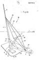
- each rotor 1, 2 has a hub 8 which is rotatably connected to a support piece 11.
- the support piece 11 is arranged on an indicated base plate 12.
- the rotor 1 comprises two A rbeitserieln 3, whose wings feet 9 are connected to the hub. 8
- the rotor 2 has only one working wing 3, to which a supporting wing 4 is assigned.
- the wing base 10 of the support wing 4 is also connected to the hub 8.
- a counterweight 6 is arranged on the free end section of the support wing 4.
- the axis of rotation 5 of the rotors 1, 2 are at an angle to the horizontal 7. of about 45 °.
- the Winkelß between the axis of rotation 5 and the working wing 3 or support wing 4 is also about 45 °.
- the bearing surface 11 can be attached to a tower-like frame, so that the rotors 1, 2 are at a distance from the ground. But it is also possible to attach the support pieces to a base plate 12, which is arranged approximately at zero level 13. Here, the base plate 12 or the support piece 11 can be connected to an actuating device which enables the rotor 1, 2 to be rotated horizontally in different directions. It is also possible to provide the rotor 1, 2 with a guiding device which can be actuated by the wind and which enables the rotor 1, 2 to always rotate in the direction of the wind flow.
- the wind turbine 33 consists of a rotor 1 with two working blades 3, which are connected by means of tensioning cables 14 to a pylon 19 arranged coaxially to the axis of rotation 5 on the hub 8.
- the main bearing 24 is located in the area of the hub 8.
- the hub 8 can e.g. be formed as shown in Fig. 7.
- the wing feet 9, 10 and the pylon 19 are combined in a ring 49.
- the ring 49 can serve to brake or lock the rotor 1, 2. It is also possible to rotate the ring 49 around fixed wheels 58 or to hold it magnetically in suspension.
- the ring 49 can also be used as a pulley for power transmission. If in this case the transmission belt 50 is crossed by 90 °, the output shaft 51 can be arranged horizontally.
- the ring 49 can be connected to a truncated cone 52 which is rotatably mounted with its free end section 53 in a journal bearing 54.
- the wind turbine 34 has a rotor 2 with a working wing 3 and a supporting wing 4.
- the working wing 3 and the supporting wing 4 are connected by means of tensioning cables 14, 20 to a pylon 19 which is also arranged coaxially to the axis of rotation 5 on the hub 8.
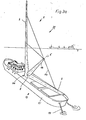
- the ship's hull 15 is anchored on the water by means of anchor chains 17 and can thereby rotate in such a way that the rotor 1 is always in the . Wind flow direction is aligned. It is also possible to fasten the ship's hull 15 to a dolphin washed into the sea floor by means of holding ropes.
- the anchor chains 17 or tether cables can be attached asymmetrically to the ship's hull 15 to compensate for one-sided moments. If, when arranging a rotor 1, 2 on a ship's hull 15, as in the case of wind turbines 33, 34, water flows such as, for example, tidal flows are to be compensated, it is expedient to use the dolphins, piles 57 or the like to attach attached tethers or chains 56 at the center of the lateral point of the ship, that is to say approximately in the middle of the ship, on the underside of the ship, for example on the keel (FIG. 3c).
- the attachment stop 55 of the tethers or chains 56 on the ship's hull 15 can be displaced to starboard or port from the longitudinal axis 59 of the ship's hull 15 (FIG. 3d).
- the water flow presses against bow and stern with approximately the same force.
- the hull 15 thus rotates only about the dolphin or pile 57, but not about itself. If the center of gravity for the rotor 1, 2 lies approximately in the center of the hub 8, the wind can move the hull 15 independently of its movement around the Turn dolphins or stake 57 around themselves in the wind.
- a sail area at the stern of the hull 15, such as a mizzen mast with sail can also be provided.
- FIG. 4a A further embodiment of a wind power plant 30 as an offshore wind power plant is shown in FIG. 4a.
- a rotor 1 with a pylon 19 is arranged on a pontoon 16 in the form of a wind turbine 33.
- the pontoon 16 is also anchored by means of anchor chains 17 so that the rotor 1 can always turn in the direction of the wind flow.
- the support piece 11 it is also possible to design the support piece 11 to be rotatable by means of an actuating device, so that the rotor 1 is rotated into the respective wind inflow direction when the pontoon 16 is stationary.
- the pontoon 16 can be rectangular as well as circular or polygonal. It is also possible to provide the pontoon 16 with lateral arms, so as to increase the stability of the pontoon 16.
- the rotor 1 is provided with further stiffening means.
- the rotor 1 is on a pontoon 16, which like can be formed in the wind turbine 35.
- the working wings 3 are connected by means of rigid connecting elements 21 which are fastened to the pylon 19.
- the connecting elements 21 are fastened to the working wings 3 by means of bearings 23.
- a cross member 25 is arranged on the upper end section of the pylon 19 and is oriented parallel to the direction of movement of the working wings 3 Counteracts gravity of the working wing 3. Between the end portions of the cross member 25 and the working wings 3, wire ropes 26 or the like are. curious; excited.
- bearings 22 are provided on the working wings 3 in the region of their longitudinal centers of gravity, to which the wire cables 26 can be fastened. It is possible to attach the wire ropes 26 and the connecting elements 21 to the working wings 3 in such a way that they can be adapted to the wind and centrifugal forces by a variable angle of attack by torsion.
- Actuating elements can be used to actuate the wire cables 26 and the connecting elements 21. These can be used as passive control elements such as springs or the like. or can be designed as active control elements such as hydraulic cylinders, motor drives or also as positive controls connected to the pylon 19, for example via eccentrics. This allows the blades 3, 4 to be adjusted cyclically to adapt to the respective operating conditions.
- a secondary rotor 32 which can be connected to an energy generating device, is arranged on the free end section of the one working wing 3. In special cases, it is conceivable that the generation of electrical energy takes place via such secondary rotors 32. However, it is also possible to use such a secondary rotor 32 as a starting aid for the rotor 1. By arranging a secondary rotor 32 appropriately on one of the working wings 3, it is possible to form a circle form flow vortex, which increases the efficiency of the other working wing 3. As a result of the improved flow against the other working wing 3, advantages are achieved with regard to the energy consumption at the wing foot 9, 10, particularly in the case of large spans.
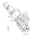
- FIG. 5a shows a possible design of a working wing 3 or supporting wing 4.
- This wing consists of a spar 37, the inside cavity 40 of which can be walked on.
- the cavity 40 serves for receiving control elements and the like.
- frames 38 are fastened at a distance from one another and are provided with a sheeting 39.
- the entire wing is divided into different wing sections 27, which are connected to one another by means of joints 28.
- the individual wing sections 27 can each be rotated relative to one another about these joints 28, so that different angles of attack of the wing sections 37 can be set in sections via the extension of the wing. This makes it possible to optimally adapt each wing to the respective inflow conditions.
- FIG. 5b A further embodiment of a working wing 3 or supporting wing 4 is shown in cross section in FIG. 5b.
- the wing core is formed by a three-belt carrier 41.
- This consists of an upper flange 42, lower flange 43 and rear flange 44.
- the rear flange 44 is located in the area of the trailing edge of the wing.
- Upper chord 42 and lower chord 43 are connected by struts 47.
- Struts 46 are arranged between the upper chord 42 or the lower chord 43 and the rear chord 44.
- the struts 46, 47 can be designed in a grid-like manner in order to increase the torsional rigidity.
- the three-belt carrier 41 is on the outside with a paneling 39 made of wood, sheet metal or the like. surround. However, a covering can also be provided in a manner known per se.
- this can also be provided with special buoyancy aids. It is also possible to form the working wing 3 from two individual wings 29, 30, which can be arranged parallel to one another one behind the other, or one above the other or also at an angle to one another. If the individual wings 29, 30 are arranged one above the other, it is expedient to connect the individual wings 29, 30 by means of profiled connecting elements 31 (FIG. 6cl.
- a wing of the rotor 1, 2 designed like a lattice mast is shown. It consists of four individual wings 29, 29a, 30, 30a, which are connected to one another by means of vertical connecting elements 31 and horizontal connecting elements 48.
- the connecting elements 31, 48 - are preferably profiled and arranged like a lattice mast, so that great inherent rigidity of the wing formed from the four individual wings 29, 29a, 30, 30a is ensured.
- connections both within the wings 3, 4 and the connecting elements 31, 48 of the grid arrangement can be made by welding, screwing, riveting or gluing. It is also possible to connect tubular belts and cross struts by means of pipe sleeves through shrink connections. This means that high-strength spring steels that cannot be welded can also be used.
- the wing weights can be used to compensate for the wind bending moments, for example in the case of a two-wing aircraft such as the rotor 2, the wing weight is selected to be approximately half of the maximum wind torque to be expected. In the case of a single-wing aircraft such as rotor 1, the wing weight is selected as approximately 1/4 of the expected wind moment.
- the support wing 4 is made unbalanced, ie, a centrifugal force is developed at full load, which is greater than that of the work wing 3. As a guideline, the centrifugal force should be about 1/4 of the expected maximum wind moment.
- power generators that are not tied to a fixed speed, such as, for example, rotor-fed asynchronous machines.
- main bearing 24 of the hub 8 it is also possible to design the main bearing 24 of the hub 8 in such a way that electrical energy can be drawn off directly in the region of the main bearing 24.
- appropriately trained electrical generator can be integrated or a magnetic system comparable to a linear motor system is used.
- the generator can be operated in parallel with an external drive device such as be connected to a gas turbine to ensure the continued generation of energy when there is no wind.
- an external drive device such as be connected to a gas turbine to ensure the continued generation of energy when there is no wind.
- the energy contained in the exhaust gases can additionally be used to generate electrical energy by means of the rotor 1, 2.
- rotors 1, 2 it is also possible to directly rotate rotors 1, 2 according to the invention with work tools such as To connect screw conveyors.
- the profile of the blades of the rotor 1, 2 is formed symmetrically in order to be independent of the wind flow direction.
- the speed of the rotor 1, 2 can also be transmitted in the area of the hub via a gearbox or directly to a drive shaft: has a screw intended for marine propulsion.
- the rotor 1, 2 is therefore also used to drive e.g. Sports boats or toy ships are suitable to let them go against the wind.
- rotors 1, 2 when operating pumped storage plants.
- a generator and a water pump are connected to each rotor 1, 2 in parallel to one another.
- water turbines are connected to the generators parallel to the rotors 1, 2.
- the rotors 1, 2 thus serve both to drive the water pumps and the generators, which can take place simultaneously or alternately.
- electrical energy can then be generated by the generators using the water turbines.
Landscapes
- Engineering & Computer Science (AREA)
- Chemical & Material Sciences (AREA)
- Mechanical Engineering (AREA)
- Combustion & Propulsion (AREA)
- Sustainable Development (AREA)
- Sustainable Energy (AREA)
- Life Sciences & Earth Sciences (AREA)
- General Engineering & Computer Science (AREA)
- Power Engineering (AREA)
- Physics & Mathematics (AREA)
- Fluid Mechanics (AREA)
- Ocean & Marine Engineering (AREA)
- Wind Motors (AREA)
- Window Of Vehicle (AREA)
- Wing Frames And Configurations (AREA)
Priority Applications (1)
| Application Number | Priority Date | Filing Date | Title |
|---|---|---|---|
| AT82108589T ATE25420T1 (de) | 1981-10-26 | 1982-09-17 | Windkraftanlage mit mindestens einem um eine drehachse drehbaren fluegel. |
Applications Claiming Priority (4)
| Application Number | Priority Date | Filing Date | Title |
|---|---|---|---|
| DE3142434 | 1981-10-26 | ||
| DE3142434 | 1981-10-26 | ||
| DE3213396 | 1982-04-10 | ||
| DE3213396 | 1982-04-10 |
Publications (2)
| Publication Number | Publication Date |
|---|---|
| EP0077914A1 true EP0077914A1 (fr) | 1983-05-04 |
| EP0077914B1 EP0077914B1 (fr) | 1987-02-04 |
Family
ID=25796884
Family Applications (1)
| Application Number | Title | Priority Date | Filing Date |
|---|---|---|---|
| EP82108589A Expired EP0077914B1 (fr) | 1981-10-26 | 1982-09-17 | Centrale éolienne comportant au moins une pale rotative |
Country Status (23)
| Country | Link |
|---|---|
| US (1) | US4624623A (fr) |
| EP (1) | EP0077914B1 (fr) |
| JP (1) | JPS58501780A (fr) |
| KR (1) | KR840002073A (fr) |
| AR (1) | AR228532A1 (fr) |
| AT (1) | ATE25420T1 (fr) |
| AU (1) | AU563109B2 (fr) |
| BR (1) | BR8207944A (fr) |
| CA (1) | CA1212333A (fr) |
| DE (1) | DE3234170C2 (fr) |
| DK (1) | DK292483A (fr) |
| ES (1) | ES516816A0 (fr) |
| FI (1) | FI832125L (fr) |
| GR (1) | GR78396B (fr) |
| HU (1) | HUT42600A (fr) |
| IL (1) | IL66973A (fr) |
| MX (1) | MX154409A (fr) |
| NO (1) | NO832289L (fr) |
| PL (1) | PL138707B1 (fr) |
| PT (1) | PT75732B (fr) |
| RO (1) | RO88449A (fr) |
| SU (1) | SU1301323A3 (fr) |
| WO (1) | WO1983001489A1 (fr) |
Cited By (1)
| Publication number | Priority date | Publication date | Assignee | Title |
|---|---|---|---|---|
| EP0193624A1 (fr) * | 1983-09-12 | 1986-09-10 | Oeko-Energie Ag | Entraînement par la force du vent |
Families Citing this family (32)
| Publication number | Priority date | Publication date | Assignee | Title |
|---|---|---|---|---|
| EP0364020B1 (fr) * | 1988-10-03 | 1992-12-30 | Josef Moser | Rotor d'éolienne |
| US5186822A (en) * | 1991-02-25 | 1993-02-16 | Ocean Resources Engineering, Inc. | Wave powered desalination apparatus with turbine-driven pressurization |
| CN1224780C (zh) * | 2000-08-17 | 2005-10-26 | 华宏荪 | 框架组合式风车 |
| US8197179B2 (en) * | 2001-06-14 | 2012-06-12 | Douglas Spriggs Selsam | Stationary co-axial multi-rotor wind turbine supported by continuous central driveshaft |
| EP1805416A1 (fr) * | 2004-10-14 | 2007-07-11 | Tommy L. Lee | Plate-forme de generation d'energie eolienne |
| CN100443718C (zh) * | 2006-05-25 | 2008-12-17 | 刘运超 | 一种斜轴式风力发电装置 |
| US8448433B2 (en) | 2008-04-09 | 2013-05-28 | Sustainx, Inc. | Systems and methods for energy storage and recovery using gas expansion and compression |
| US8225606B2 (en) | 2008-04-09 | 2012-07-24 | Sustainx, Inc. | Systems and methods for energy storage and recovery using rapid isothermal gas expansion and compression |
| US8479505B2 (en) | 2008-04-09 | 2013-07-09 | Sustainx, Inc. | Systems and methods for reducing dead volume in compressed-gas energy storage systems |
| US8037678B2 (en) | 2009-09-11 | 2011-10-18 | Sustainx, Inc. | Energy storage and generation systems and methods using coupled cylinder assemblies |
| EP2280841A2 (fr) | 2008-04-09 | 2011-02-09 | Sustainx, Inc. | Systèmes et procédés de stockage et de récupération d'énergie à l aide de gaz comprimé |
| US8677744B2 (en) | 2008-04-09 | 2014-03-25 | SustaioX, Inc. | Fluid circulation in energy storage and recovery systems |
| US20100307156A1 (en) | 2009-06-04 | 2010-12-09 | Bollinger Benjamin R | Systems and Methods for Improving Drivetrain Efficiency for Compressed Gas Energy Storage and Recovery Systems |
| US8240140B2 (en) | 2008-04-09 | 2012-08-14 | Sustainx, Inc. | High-efficiency energy-conversion based on fluid expansion and compression |
| US7958731B2 (en) | 2009-01-20 | 2011-06-14 | Sustainx, Inc. | Systems and methods for combined thermal and compressed gas energy conversion systems |
| US8474255B2 (en) | 2008-04-09 | 2013-07-02 | Sustainx, Inc. | Forming liquid sprays in compressed-gas energy storage systems for effective heat exchange |
| US8250863B2 (en) | 2008-04-09 | 2012-08-28 | Sustainx, Inc. | Heat exchange with compressed gas in energy-storage systems |
| US8359856B2 (en) | 2008-04-09 | 2013-01-29 | Sustainx Inc. | Systems and methods for efficient pumping of high-pressure fluids for energy storage and recovery |
| WO2009152141A2 (fr) | 2008-06-09 | 2009-12-17 | Sustainx, Inc. | Système et procédé pour la détente et la compression isotherme rapide de gaz pour le stockage d'énergie |
| KR101028748B1 (ko) * | 2008-08-08 | 2011-04-14 | 이달은 | 대형 풍력발전기 |
| US7963110B2 (en) | 2009-03-12 | 2011-06-21 | Sustainx, Inc. | Systems and methods for improving drivetrain efficiency for compressed gas energy storage |
| US8104274B2 (en) | 2009-06-04 | 2012-01-31 | Sustainx, Inc. | Increased power in compressed-gas energy storage and recovery |
| WO2011056855A1 (fr) | 2009-11-03 | 2011-05-12 | Sustainx, Inc. | Systèmes et procédés de stockage d'énergie produite par un gaz comprimé au moyen d'ensembles vérins couplés |
| US8191362B2 (en) | 2010-04-08 | 2012-06-05 | Sustainx, Inc. | Systems and methods for reducing dead volume in compressed-gas energy storage systems |
| US8171728B2 (en) | 2010-04-08 | 2012-05-08 | Sustainx, Inc. | High-efficiency liquid heat exchange in compressed-gas energy storage systems |
| US8234863B2 (en) | 2010-05-14 | 2012-08-07 | Sustainx, Inc. | Forming liquid sprays in compressed-gas energy storage systems for effective heat exchange |
| US8747070B2 (en) * | 2010-07-13 | 2014-06-10 | Greg E Blonder | Spinning horizontal axis wind turbine |
| US8495872B2 (en) | 2010-08-20 | 2013-07-30 | Sustainx, Inc. | Energy storage and recovery utilizing low-pressure thermal conditioning for heat exchange with high-pressure gas |
| US8578708B2 (en) | 2010-11-30 | 2013-11-12 | Sustainx, Inc. | Fluid-flow control in energy storage and recovery systems |
| JP2014522460A (ja) | 2011-05-17 | 2014-09-04 | サステインエックス, インコーポレイテッド | 圧縮空気エネルギー貯蔵システムにおける効率的二相熱移送のためのシステムおよび方法 |
| US20130091836A1 (en) | 2011-10-14 | 2013-04-18 | Sustainx, Inc. | Dead-volume management in compressed-gas energy storage and recovery systems |
| US12071931B2 (en) * | 2019-07-27 | 2024-08-27 | Siva RaghuRam Prasad Chennupati | Universal propeller, operating method and favoured use |
Citations (11)
| Publication number | Priority date | Publication date | Assignee | Title |
|---|---|---|---|---|
| FR542172A (fr) * | 1921-10-11 | 1922-08-07 | Perfectionnements apportés aux appareils moteurs fonctionnant sous l'action du vent | |
| DE577917C (de) * | 1927-06-27 | 1933-06-07 | Expl Des Procedes Maurice Lebl | Mit einem elektrischen Stromerzeuger gekuppeltes Windrad |
| US2627928A (en) * | 1945-04-30 | 1953-02-10 | Alexander S Mullgardt | Propeller |
| DE877280C (de) * | 1947-02-03 | 1953-05-21 | Richard Bauer | Windkraftmaschine |
| DE907400C (de) * | 1943-12-21 | 1954-03-25 | Richard Bauer | Windkraftanlage |
| DE2753956B1 (de) * | 1977-12-03 | 1979-03-22 | Maschf Augsburg Nuernberg Ag | Wartungs- bzw. Inspektionseinrichtung fuer Grosswindenergieanlagen |
| DE2806874A1 (de) * | 1976-08-26 | 1979-08-23 | Praktisk Teknik Ab | Horizontalachsenrotor, vorzugsweise fuer windkraftwerke |
| FR2464384A1 (fr) * | 1979-08-28 | 1981-03-06 | Charpentier Pierre | Dispositif recuperateur de l'energie cinetique d'un fluide en ecoulement |
| DE2940485A1 (de) * | 1978-02-23 | 1981-04-16 | Sidney Philadelphia Pa. Dvorak | Anlage zur erzeugung elektrischer energie |
| DE2944718A1 (de) * | 1979-11-06 | 1981-05-21 | Hans-Dietrich Ing.(grad.) 2000 Hamburg Goslich | Rotor fuer windkraftanlagen in leichtbauweise |
| FR2486018A1 (fr) * | 1980-07-03 | 1982-01-08 | Henry Eugene | Propulsion d'un navire par eolienne du type darrieux a geometrie variable (type tronconique) |
Family Cites Families (24)
| Publication number | Priority date | Publication date | Assignee | Title |
|---|---|---|---|---|
| US869709A (en) * | 1906-09-28 | 1907-10-29 | Josef Homola | Machine for use with wind-power. |
| NL7176C (fr) * | 1918-07-17 | |||
| US1883336A (en) * | 1925-02-12 | 1932-10-18 | Chillingworth Rudolph | Screw propeller for aircraft |
| US2152984A (en) * | 1936-08-17 | 1939-04-04 | Wilford Edward Burke | Watercraft |
| FR993473A (fr) * | 1949-06-28 | 1951-10-31 | Installation productrice d'énergie par l'action du vent | |
| US2661068A (en) * | 1950-09-02 | 1953-12-01 | Leo B Gaskill | Air circulator for orchards and field crops |
| CH356366A (fr) * | 1959-12-07 | 1961-08-15 | Marbury Fendall Jr | Procédé de propulsion d'un navire et installation pour la mise en oeuvre de ce procédé |
| DE1120390B (de) * | 1961-03-18 | 1961-12-21 | Wilhelm Goldau | Vertikale Einfluegelwindkraftmaschine mit abgewinkelter Abtriebswelle |
| DE2814247A1 (de) * | 1977-04-05 | 1978-10-19 | Daniel Henggeler | Windkraftmaschine |
| DK140382B (da) * | 1977-07-25 | 1979-08-13 | Peder Ulrik Poulsen | Vindmotor. |
| DE2737767C2 (de) * | 1977-08-22 | 1979-05-17 | Ulrich Prof. Dr.-Ing. 7312 Kirchheim Huetter | Windkraftanlage |
| US4168439A (en) * | 1977-11-28 | 1979-09-18 | Palma F Neto | Wind turbine |
| US4264279A (en) * | 1978-05-12 | 1981-04-28 | Dereng Viggo G | Fixed geometry self starting transverse axis wind turbine |
| SE414073B (sv) * | 1978-10-06 | 1980-07-07 | Ljungstrom Olle | Vindturbin av tverstromstyp sa kallad bagbladstyp eller darrievstyp resp giromilltyp med fast eller pa kent sett cykliskt reglerbar bladvinkel |
| DE2844262A1 (de) * | 1978-10-11 | 1980-04-17 | Franz Xaver Prof Dr I Wortmann | Einblattrotor fuer windturbinen |
| JPS5579319A (en) * | 1978-12-07 | 1980-06-14 | Shiyaaman Baaton | Method of introducing vitamine a analogue to respiratory tract of smoker |
| GB2049831A (en) * | 1979-05-29 | 1980-12-31 | Chabek K | Wind Turbine Plant |
| US4355956A (en) * | 1979-12-26 | 1982-10-26 | Leland O. Lane | Wind turbine |
| FR2473639A1 (fr) * | 1980-01-16 | 1981-07-17 | Aeropower | Aerogenerateur a axe d'orientation commande |
| US4360315A (en) * | 1980-04-14 | 1982-11-23 | Leonard Olson | Vortex wind turbine |
| US4353702A (en) * | 1980-07-21 | 1982-10-12 | F M Machine Company | Sailing craft mainsail and auxiliary propulsion means therefor |
| DE3039387A1 (de) * | 1980-10-18 | 1982-06-03 | Bernhard 6800 Mannheim Jöst | Windantrieb fuer fahrzeuge und stationaere maschinen jeder art |
| US4432695A (en) * | 1981-10-29 | 1984-02-21 | Institut Gidrodinamiki Imeni M.A. Lavrentieva | Wind motor |
| US4533297A (en) * | 1982-09-15 | 1985-08-06 | Bassett David A | Rotor system for horizontal axis wind turbines |
-
1982
- 1982-09-15 DE DE3234170A patent/DE3234170C2/de not_active Expired
- 1982-09-17 WO PCT/DE1982/000186 patent/WO1983001489A1/fr not_active Ceased
- 1982-09-17 AU AU89047/82A patent/AU563109B2/en not_active Ceased
- 1982-09-17 HU HU823401A patent/HUT42600A/hu unknown
- 1982-09-17 JP JP57502817A patent/JPS58501780A/ja active Pending
- 1982-09-17 AT AT82108589T patent/ATE25420T1/de not_active IP Right Cessation
- 1982-09-17 RO RO11140382A patent/RO88449A/fr unknown
- 1982-09-17 EP EP82108589A patent/EP0077914B1/fr not_active Expired
- 1982-09-17 BR BR8207944A patent/BR8207944A/pt unknown
- 1982-09-17 FI FI832125A patent/FI832125L/fi not_active Application Discontinuation
- 1982-10-12 IL IL66973A patent/IL66973A/xx unknown
- 1982-10-19 GR GR69571A patent/GR78396B/el unknown
- 1982-10-25 PT PT75732A patent/PT75732B/pt unknown
- 1982-10-25 ES ES516816A patent/ES516816A0/es active Granted
- 1982-10-25 CA CA000414096A patent/CA1212333A/fr not_active Expired
- 1982-10-26 PL PL1982238737A patent/PL138707B1/pl unknown
- 1982-10-26 MX MX194941A patent/MX154409A/es unknown
- 1982-10-26 KR KR1019820004797A patent/KR840002073A/ko not_active Ceased
- 1982-10-26 AR AR291096A patent/AR228532A1/es active
-
1983
- 1983-06-23 NO NO832289A patent/NO832289L/no unknown
- 1983-06-24 DK DK292483A patent/DK292483A/da not_active Application Discontinuation
- 1983-06-24 SU SU833609883A patent/SU1301323A3/ru active
-
1985
- 1985-03-20 US US06/714,614 patent/US4624623A/en not_active Expired - Fee Related
Patent Citations (11)
| Publication number | Priority date | Publication date | Assignee | Title |
|---|---|---|---|---|
| FR542172A (fr) * | 1921-10-11 | 1922-08-07 | Perfectionnements apportés aux appareils moteurs fonctionnant sous l'action du vent | |
| DE577917C (de) * | 1927-06-27 | 1933-06-07 | Expl Des Procedes Maurice Lebl | Mit einem elektrischen Stromerzeuger gekuppeltes Windrad |
| DE907400C (de) * | 1943-12-21 | 1954-03-25 | Richard Bauer | Windkraftanlage |
| US2627928A (en) * | 1945-04-30 | 1953-02-10 | Alexander S Mullgardt | Propeller |
| DE877280C (de) * | 1947-02-03 | 1953-05-21 | Richard Bauer | Windkraftmaschine |
| DE2806874A1 (de) * | 1976-08-26 | 1979-08-23 | Praktisk Teknik Ab | Horizontalachsenrotor, vorzugsweise fuer windkraftwerke |
| DE2753956B1 (de) * | 1977-12-03 | 1979-03-22 | Maschf Augsburg Nuernberg Ag | Wartungs- bzw. Inspektionseinrichtung fuer Grosswindenergieanlagen |
| DE2940485A1 (de) * | 1978-02-23 | 1981-04-16 | Sidney Philadelphia Pa. Dvorak | Anlage zur erzeugung elektrischer energie |
| FR2464384A1 (fr) * | 1979-08-28 | 1981-03-06 | Charpentier Pierre | Dispositif recuperateur de l'energie cinetique d'un fluide en ecoulement |
| DE2944718A1 (de) * | 1979-11-06 | 1981-05-21 | Hans-Dietrich Ing.(grad.) 2000 Hamburg Goslich | Rotor fuer windkraftanlagen in leichtbauweise |
| FR2486018A1 (fr) * | 1980-07-03 | 1982-01-08 | Henry Eugene | Propulsion d'un navire par eolienne du type darrieux a geometrie variable (type tronconique) |
Non-Patent Citations (1)
| Title |
|---|
| THE ENGINEER, Band 239, Nr. 6180/81, 22./29. August 1974, Seiten 55-59, Morgan-Grampian Ltd., London, G.B. * |
Cited By (1)
| Publication number | Priority date | Publication date | Assignee | Title |
|---|---|---|---|---|
| EP0193624A1 (fr) * | 1983-09-12 | 1986-09-10 | Oeko-Energie Ag | Entraînement par la force du vent |
Also Published As
| Publication number | Publication date |
|---|---|
| DE3234170A1 (de) | 1983-05-11 |
| PT75732B (en) | 1984-12-03 |
| PT75732A (en) | 1982-11-01 |
| AR228532A1 (es) | 1983-03-15 |
| IL66973A (en) | 1988-06-30 |
| PL238737A1 (en) | 1983-06-20 |
| MX154409A (es) | 1987-08-11 |
| DK292483D0 (da) | 1983-06-24 |
| BR8207944A (pt) | 1983-09-20 |
| FI832125A7 (fi) | 1983-06-14 |
| CA1212333A (fr) | 1986-10-07 |
| US4624623A (en) | 1986-11-25 |
| KR840002073A (ko) | 1984-06-11 |
| EP0077914B1 (fr) | 1987-02-04 |
| GR78396B (fr) | 1984-09-27 |
| DE3234170C2 (de) | 1985-04-11 |
| ES8307340A1 (es) | 1983-06-16 |
| PL138707B1 (en) | 1986-10-31 |
| HUT42600A (en) | 1987-07-28 |
| ATE25420T1 (de) | 1987-02-15 |
| FI832125A0 (fi) | 1983-06-14 |
| DK292483A (da) | 1983-06-24 |
| NO832289L (no) | 1983-06-23 |
| WO1983001489A1 (fr) | 1983-04-28 |
| FI832125L (fi) | 1983-06-14 |
| AU8904782A (en) | 1983-05-05 |
| ES516816A0 (es) | 1983-06-16 |
| JPS58501780A (ja) | 1983-10-20 |
| RO88449A (fr) | 1986-01-30 |
| SU1301323A3 (ru) | 1987-03-30 |
| AU563109B2 (en) | 1987-06-25 |
Similar Documents
| Publication | Publication Date | Title |
|---|---|---|
| EP0077914B1 (fr) | Centrale éolienne comportant au moins une pale rotative | |
| DE102007013293B3 (de) | Verfahren und Vorrichtung zum Betrieb eines Unterwasserkraftwerks | |
| US11208982B2 (en) | System for generating electric energy from wind or hydraulic energy | |
| DE10205988A1 (de) | Windenergieanlage | |
| WO1982003662A1 (fr) | Installation pour l'exploitation du vent et des vagues | |
| EP3601787A1 (fr) | Éolienne flottante offshore comprenant un rotor vertical et parc éolien de construction modulaire comprenant plusieurs éoliennes de ce type | |
| DE19744174A1 (de) | Luftströmungskonverter zur Erzeugung schadstofffreier Elektroenergie auf dem Meer | |
| DE102008057212A1 (de) | Rotor mit mindestens einem ringförmigen Rotorblatt | |
| DE102013202566B3 (de) | Windkraftanlage | |
| US20210062788A1 (en) | Ducted wind turbine and support platform | |
| DE102008008060B4 (de) | Rotor mit einem parallel zur Rotationsachse angeströmten, ringförmigen Rotorblatt | |
| WO2003103113A2 (fr) | Rotor vertical a pales orientables | |
| EP4440928A1 (fr) | Dispositif comprenant un profil d'aile réglable asymétrique | |
| DE2905569A1 (de) | Windturbinenkraftwerk | |
| EP0193624A1 (fr) | Entraînement par la force du vent | |
| CN1009569B (zh) | 摆翼式立轴风力机 | |
| DE102007057077A1 (de) | Rotor mit einem parallel zur Rotationsachse angeströmten ringförmigen Rotorblatt | |
| DE102004012712A1 (de) | Bauliche Anlage zur Umwandlung von Wind- in Elektroenergie | |
| DE202010016041U1 (de) | Windkraftanlage und Windpark | |
| DD205722A5 (de) | Windkraftanlage | |
| EP3688304B1 (fr) | Générateur/dispositif d'entraînement de surfaces de support oscillantes pour la conversion d'énergie | |
| DE202021003974U1 (de) | Offshore- Strömungskraftanlage zur Stromgewinnung | |
| DE10325342A1 (de) | Vertikaler Rotor mit lenkbaren Flügeln | |
| DE102009013161A1 (de) | Hochleistungs-Hubflügelsystem zur Windenergienutzung | |
| DE102021006455A1 (de) | Offshore-Strömungskraftanlage zur Stromgewinnung |
Legal Events
| Date | Code | Title | Description |
|---|---|---|---|
| PUAI | Public reference made under article 153(3) epc to a published international application that has entered the european phase |
Free format text: ORIGINAL CODE: 0009012 |
|
| AK | Designated contracting states |
Designated state(s): AT BE CH FR GB IT LI NL SE |
|
| 17P | Request for examination filed |
Effective date: 19831111 |
|
| D17P | Request for examination filed (deleted) | ||
| R17P | Request for examination filed (corrected) |
Effective date: 19831111 |
|
| GRAA | (expected) grant |
Free format text: ORIGINAL CODE: 0009210 |
|
| AK | Designated contracting states |
Kind code of ref document: B1 Designated state(s): AT BE CH FR GB IT LI NL SE |
|
| REF | Corresponds to: |
Ref document number: 25420 Country of ref document: AT Date of ref document: 19870215 Kind code of ref document: T |
|
| ITF | It: translation for a ep patent filed | ||
| ET | Fr: translation filed | ||
| PGFP | Annual fee paid to national office [announced via postgrant information from national office to epo] |
Ref country code: NL Payment date: 19870930 Year of fee payment: 6 |
|
| PLBE | No opposition filed within time limit |
Free format text: ORIGINAL CODE: 0009261 |
|
| STAA | Information on the status of an ep patent application or granted ep patent |
Free format text: STATUS: NO OPPOSITION FILED WITHIN TIME LIMIT |
|
| 26N | No opposition filed | ||
| PG25 | Lapsed in a contracting state [announced via postgrant information from national office to epo] |
Ref country code: GB Effective date: 19880917 Ref country code: AT Effective date: 19880917 |
|
| PG25 | Lapsed in a contracting state [announced via postgrant information from national office to epo] |
Ref country code: SE Effective date: 19880918 |
|
| PG25 | Lapsed in a contracting state [announced via postgrant information from national office to epo] |
Ref country code: BE Effective date: 19880930 |
|
| BERE | Be: lapsed |
Owner name: OKO-ENERGIE A.G. Effective date: 19880930 |
|
| PG25 | Lapsed in a contracting state [announced via postgrant information from national office to epo] |
Ref country code: NL Effective date: 19890401 |
|
| NLV4 | Nl: lapsed or anulled due to non-payment of the annual fee | ||
| PG25 | Lapsed in a contracting state [announced via postgrant information from national office to epo] |
Ref country code: FR Free format text: LAPSE BECAUSE OF NON-PAYMENT OF DUE FEES Effective date: 19890531 |
|
| GBPC | Gb: european patent ceased through non-payment of renewal fee | ||
| REG | Reference to a national code |
Ref country code: FR Ref legal event code: ST |
|
| EUG | Se: european patent has lapsed |
Ref document number: 82108589.1 Effective date: 19890614 |
|
| PGFP | Annual fee paid to national office [announced via postgrant information from national office to epo] |
Ref country code: CH Payment date: 20001231 Year of fee payment: 19 |
|
| PG25 | Lapsed in a contracting state [announced via postgrant information from national office to epo] |
Ref country code: LI Free format text: LAPSE BECAUSE OF NON-PAYMENT OF DUE FEES Effective date: 20010930 Ref country code: CH Free format text: LAPSE BECAUSE OF NON-PAYMENT OF DUE FEES Effective date: 20010930 |
|
| REG | Reference to a national code |
Ref country code: CH Ref legal event code: PL |