EP0077931A2 - Hélice de propulsion pour bateau - Google Patents
Hélice de propulsion pour bateau Download PDFInfo
- Publication number
- EP0077931A2 EP0077931A2 EP82109033A EP82109033A EP0077931A2 EP 0077931 A2 EP0077931 A2 EP 0077931A2 EP 82109033 A EP82109033 A EP 82109033A EP 82109033 A EP82109033 A EP 82109033A EP 0077931 A2 EP0077931 A2 EP 0077931A2
- Authority
- EP
- European Patent Office
- Prior art keywords
- ship
- propeller
- air
- air outlet
- propeller according
- Prior art date
- Legal status (The legal status is an assumption and is not a legal conclusion. Google has not performed a legal analysis and makes no representation as to the accuracy of the status listed.)
- Withdrawn
Links
- XLYOFNOQVPJJNP-UHFFFAOYSA-N water Substances O XLYOFNOQVPJJNP-UHFFFAOYSA-N 0.000 claims description 41
- 229910000831 Steel Inorganic materials 0.000 description 1
- 238000009825 accumulation Methods 0.000 description 1
- 230000015572 biosynthetic process Effects 0.000 description 1
- 230000000994 depressogenic effect Effects 0.000 description 1
- 230000000694 effects Effects 0.000 description 1
- 238000004519 manufacturing process Methods 0.000 description 1
- 239000002184 metal Substances 0.000 description 1
- 230000002787 reinforcement Effects 0.000 description 1
- 239000010959 steel Substances 0.000 description 1
- 238000003260 vortexing Methods 0.000 description 1
Images


Classifications
-
- B—PERFORMING OPERATIONS; TRANSPORTING
- B63—SHIPS OR OTHER WATERBORNE VESSELS; RELATED EQUIPMENT
- B63H—MARINE PROPULSION OR STEERING
- B63H1/00—Propulsive elements directly acting on water
- B63H1/02—Propulsive elements directly acting on water of rotary type
- B63H1/12—Propulsive elements directly acting on water of rotary type with rotation axis substantially in propulsive direction
- B63H1/14—Propellers
- B63H1/28—Other means for improving propeller efficiency
-
- B—PERFORMING OPERATIONS; TRANSPORTING
- B63—SHIPS OR OTHER WATERBORNE VESSELS; RELATED EQUIPMENT
- B63H—MARINE PROPULSION OR STEERING
- B63H5/00—Arrangements on vessels of propulsion elements directly acting on water
- B63H5/07—Arrangements on vessels of propulsion elements directly acting on water of propellers
-
- B—PERFORMING OPERATIONS; TRANSPORTING
- B63—SHIPS OR OTHER WATERBORNE VESSELS; RELATED EQUIPMENT
- B63H—MARINE PROPULSION OR STEERING
- B63H1/00—Propulsive elements directly acting on water
- B63H1/02—Propulsive elements directly acting on water of rotary type
- B63H1/12—Propulsive elements directly acting on water of rotary type with rotation axis substantially in propulsive direction
- B63H1/14—Propellers
- B63H1/28—Other means for improving propeller efficiency
- B63H2001/286—Injection of gas into fluid flow to propellers, or around propeller blades
-
- B—PERFORMING OPERATIONS; TRANSPORTING
- B63—SHIPS OR OTHER WATERBORNE VESSELS; RELATED EQUIPMENT
- B63H—MARINE PROPULSION OR STEERING
- B63H5/00—Arrangements on vessels of propulsion elements directly acting on water
- B63H5/07—Arrangements on vessels of propulsion elements directly acting on water of propellers
- B63H5/08—Arrangements on vessels of propulsion elements directly acting on water of propellers of more than one propeller
-
- B—PERFORMING OPERATIONS; TRANSPORTING
- B63—SHIPS OR OTHER WATERBORNE VESSELS; RELATED EQUIPMENT
- B63H—MARINE PROPULSION OR STEERING
- B63H5/00—Arrangements on vessels of propulsion elements directly acting on water
- B63H5/07—Arrangements on vessels of propulsion elements directly acting on water of propellers
- B63H5/16—Arrangements on vessels of propulsion elements directly acting on water of propellers characterised by being mounted in recesses; with stationary water-guiding elements; Means to prevent fouling of the propeller, e.g. guards, cages or screens
Definitions
- the idea of the invention is based on the fact that water is always applied to the pressure side of the propeller blades, but that on the suction side, of course, a vacuum is generated on the suction side due to the larger angle of attack required, which runs behind the rotating propeller blades.
- the power wasted here is usually more than 1/3 of the power applied. This means that the swirling of the water can be reduced here, this would mean a corresponding increase in economy.
- the object of the present invention is to significantly increase the efficiency of the propeller and to generate a water flow mixed with air which has no or only very little loss due to whirling of the propeller flow. Furthermore, the speed of rotation should be increased significantly.
- the air flowing out behind the propeller blade not only prevents a vacuum and thus the risk of cavitation, it also reduces the vortexing of the water in the propeller by approx. 50% and thus increases the output by approx. 20%.
- the steadfastness of the water is used so that the pressure side does not already cause excessive swirling, and a higher propeller speed is achieved than before. A constriction of the water flow behind the propeller is avoided.
- much narrower propellers are used according to the invention than is customary in the conventional propeller.
- the air supply to the propeller is supported or only achieved by the blades reaching through the coaxial jacket or ring on one inner propeller shaft or hub are attached and use these inner areas to suck in air for the air outlet openings.
- a streamlined air supply is created in that the air outlet openings adjoin a region of the opening edge on the rear of the wing. Only one air outlet opening can be provided in the casing or ring for each wing.
- the propeller be part of a streamlined drive unit which is fastened on the outside near the hull.
- the drive unit described makes it possible to introduce a sufficient amount of air into the various openings, which can be in front, in and behind the propeller, without the support of a blower, in order to firstly supply air to the suction side of the propeller blades and secondly to constrict the Avoid the propeller flow behind the propeller to a large extent, so that a cylindrical pressure build-up in the outflowing water is achieved.
- the propellers arranged at the front not only prevent a water trough at the stern and a water mountain at the bow, they also create a water trough at the bow into which the ship runs. So a kind of descent is created. It can be ensured that the expelled water is brought under the stern, so that the descent is intensified. An even greater reinforcement of the descent is generated by the fact that air is released from the propeller with the water that is expelled which is contained in the ejected water column and gets under the hull, in particular the stern, in order to generate a buoyancy there like an air cushion. This further improves the ship's position in the water.
- the air ejected by the ship's propellers reaches the outer wall of the hull in the form of air bubbles in order to generate an air accumulation there, in particular an air film, which reduces the friction between the water and the wall.
- the off-center propellers should be directed obliquely towards the middle of the ship, so that the columnar amounts of water mixed with air will surely get under the middle of the hull and not escape laterally and therefore also flow under the rear area of the hull. This leads to an optimal use of the air quantities brought under the ship's hull and thus to an optimal buoyancy and lowest friction.
- Optimal alignment of the off-center propellers even after the ship has been created and in particular in accordance with different ship speeds is achieved in that the off-center propellers can be rotated about an approximately vertical axis.
- walls extend into the water on both sides of the ship parallel to the longitudinal axis of the ship, which form a channel open to the front, back and down below the hull through which the water displaced by the propellers flows. This prevents the air or the air cushion from escaping and the air film to the sides are prevented, and further the propellers protruding under the ship's floor are protected from ground contact.
- a particularly advantageous embodiment is provided when the propeller has central air outlet openings on the pressure side.
- a very large amount of air can be injected into the water being drawn off, the propeller sucking in the air. Due to the central introduction of the air, the air remains in the tubular water jet for a relatively long time as a tubular air jet and can thus get to a convenient location on the hull, in particular of the stern, so that buoyancy is generated there like an air cushion.
- the middle air outlet opening is preferably arranged at the rear end of the propeller hub or shaft.
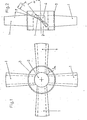
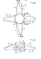
- the propeller in the exemplary embodiment according to FIGS. 1 and 2 has four blades 1 which are attached to a hub 2 at the angle of attack ⁇ attached and which are stiffened by a coaxial casing ring 3.
- the casing ring 3 forms an annular spacing 3a with the hub 2.
- the wings are around the ⁇ twisted and on the front sides around the arrowed ⁇ .
- the blades extend through the casing ring 3 and are attached with their inner ends to the propeller hub 2.
- the wing regions 1a between the hub 2 and the ring 3 suck in air through the spacing space 3a, since the spacing space is connected to air supply channels.
- Triangular air outlet openings 4 are cut out in the casing ring 3, on the back of the wings, of which an opening edge region adjoins the rear side of the wing.
- the wings 1 can be inserted through the openings 4.
- the hub 2 has a conical bore 5 for attachment to the drive shaft 6.
- the drive shaft 6 is in the Bearings 7 and 8 and is driven by a bevel gear 9 from an oblique drive shaft 25.
- the bearings 7 and 8 are mounted in a junction box 10, which is attached below the bow 11.
- the propeller turns in the direction of arrow D and propels the ship forward in direction C.
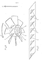
- the water 20 (shown as lines) is cut off by the propeller blades rotating in direction D and accelerated in the direction of arrow E by the front side 21 of the propeller.
- a strong suction occurs on the rear of the propeller 22 because the water cannot flow in as quickly, a vacuum 23 is created.
- This vacuum 23 leads to a deflection of the water flowing in from the direction of travel, and the vacuum also makes the accelerated water from the direction of travel deflected diagonally, which corresponds to a spiral twist due to the rotation.
- Vacuum formation is prevented by the vacuum 23 being filled by air 24 through the openings 4, as a result of which no suction is exerted on the water, and the propeller continues to flow directly, and the accelerated water is also not deflected. In this way, the full drive power is used for the forward movement.
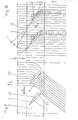
- the tubes 12 open into a streamlined, in particular torpedo-shaped, drive unit U fastened below the hull with a front, vertical, hollow body 14 having the cross-section of a lens as a support on the latter End is a conical hollow body 15 with a horizontal axis.
- the air flows out of the hollow body 14 Via the opening 16 into the hollow body 15.
- a certain amount of air can escape via the annular gap 17 between the hollow body 15 and the ring 3.
- Most of the air is directed via the wing areas 1a, which are located between the hub 2 and the hub ring 3, through the triangular openings 4 to the suction side of the propeller, where it is then carried away by the pressurized water.
- a cylindrical casing 6a adjoins the casing ring 3, which coaxially surrounds the drive shaft 6 and the bearings 7, 8 and has a somewhat smaller diameter than the casing ring 3.
- the tube 13 opens into an essentially rectangular hollow body 18 which is open to the rear and to the front and is closed in a semicircular shape at the bottom. Due to the suction effect of the water, air is sucked through the opening 19 out of the hollow body 18 and the tube 13, which then mixes with the water.
- the lateral propellers 104 can be rotatably adjustable on a vertical axis or, according to CL, from the vertical, inclined axis, in order to optimally align the air / water column. While only two propellers 104 are arranged in the embodiment according to FIGS. 13 to 14, both of which lie outside the center, according to the embodiment according to FIGS. 15 to 17 three propellers are fastened to the bow, of which only the two outer angles form an angle with the form the vertical longitudinal plane E.
- the inclined position of the outer propellers 104 ensures that the air / water columns reach the center of the hull, so that the air does not escape laterally prematurely and at the same time sufficient air reaches the stern 105 of the ship.
- the hull has two side walls (runners) 106 parallel to the longitudinal axis of the ship, which form a channel 106a below the ship, which is open at the front and rear as well as downwards.
- the propellers 104 are arranged in this channel, the walls projecting lower than the propellers.
- the hub 107 or the tubular propeller shaft has a central air outlet opening 108 on the propeller pressure side D, the diameter of which is approximately 1/3 of the diameter of the propeller.
- the air emerging from this opening 108 through the propeller suction forms a central air column 110 (FIG. 18) in the water column 109 pushed off by the propeller, which remains far behind the propeller and supplies air to the central rear fuselage area.
- the air is supplied to the propeller hub 107 via the propeller drive shaft and an air supply pipe 111.
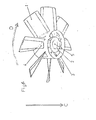
- the propeller blades 112 are formed by two walls 112a made of sheet metal, in particular sheet steel, which are designed in an arc shape and which are connected to one another in cross section at the leading leading edge 113 and at the opposite trailing edge (trailing edge ) 114 form a gap 115 on the suction side S, which extends to the periphery of the wing and to the rear edge and emerges from the air.
- the gap 115 thus opens the cavity 116 of the wing 112, the cavity 116 being connected to the air supply via openings 117 in the hub side wall.
- the openings 117 have different sizes, corresponding to the increasing thickness of the wing profile from the leading edge 113 to the trailing edge 114.
Landscapes
- Chemical & Material Sciences (AREA)
- Engineering & Computer Science (AREA)
- Combustion & Propulsion (AREA)
- Mechanical Engineering (AREA)
- Ocean & Marine Engineering (AREA)
- Engine Equipment That Uses Special Cycles (AREA)
- Structures Of Non-Positive Displacement Pumps (AREA)
Applications Claiming Priority (2)
| Application Number | Priority Date | Filing Date | Title |
|---|---|---|---|
| DE3142498 | 1981-10-27 | ||
| DE3142498 | 1981-10-27 |
Publications (1)
| Publication Number | Publication Date |
|---|---|
| EP0077931A2 true EP0077931A2 (fr) | 1983-05-04 |
Family
ID=6144893
Family Applications (1)
| Application Number | Title | Priority Date | Filing Date |
|---|---|---|---|
| EP82109033A Withdrawn EP0077931A2 (fr) | 1981-10-27 | 1982-09-30 | Hélice de propulsion pour bateau |
Country Status (2)
| Country | Link |
|---|---|
| EP (1) | EP0077931A2 (fr) |
| JP (1) | JPS5881893A (fr) |
Cited By (6)
| Publication number | Priority date | Publication date | Assignee | Title |
|---|---|---|---|---|
| US5083950A (en) * | 1988-12-22 | 1992-01-28 | Vosper Thornycroft (Uk) Limited | Apparatus for reducing cavitation erosion |
| WO1999039973A1 (fr) * | 1998-02-07 | 1999-08-12 | Futuretech Technologies Limited | Systeme de propulsion |
| JP2013103717A (ja) * | 2011-11-11 | 2013-05-30 | Becker Marine Systems Gmbh & Co Kg | 船舶の駆動力要件を低減するための装置 |
| WO2014020551A1 (fr) * | 2012-07-31 | 2014-02-06 | Hawkins Russel Ian | Hélice comprenant un système de propulsion secondaire |
| US9908600B2 (en) | 2012-07-31 | 2018-03-06 | Russel Ian Hawkins | Propeller including a discrete blade edge cover member |
| CN115092358A (zh) * | 2022-07-12 | 2022-09-23 | 菏泽市产品检验检测研究院 | 一种氢氧燃料电池供电的潜水服 |
Families Citing this family (1)
| Publication number | Priority date | Publication date | Assignee | Title |
|---|---|---|---|---|
| JP2947357B2 (ja) * | 1989-08-18 | 1999-09-13 | 日産自動車株式会社 | 高速艇のプロペラ構造 |
-
1982
- 1982-09-30 EP EP82109033A patent/EP0077931A2/fr not_active Withdrawn
- 1982-10-27 JP JP18765682A patent/JPS5881893A/ja active Pending
Cited By (9)
| Publication number | Priority date | Publication date | Assignee | Title |
|---|---|---|---|---|
| US5083950A (en) * | 1988-12-22 | 1992-01-28 | Vosper Thornycroft (Uk) Limited | Apparatus for reducing cavitation erosion |
| WO1999039973A1 (fr) * | 1998-02-07 | 1999-08-12 | Futuretech Technologies Limited | Systeme de propulsion |
| US6332818B1 (en) * | 1998-02-07 | 2001-12-25 | Futuretech Technologies Limited | Propulsion system |
| JP2013103717A (ja) * | 2011-11-11 | 2013-05-30 | Becker Marine Systems Gmbh & Co Kg | 船舶の駆動力要件を低減するための装置 |
| WO2014020551A1 (fr) * | 2012-07-31 | 2014-02-06 | Hawkins Russel Ian | Hélice comprenant un système de propulsion secondaire |
| US9701379B2 (en) | 2012-07-31 | 2017-07-11 | Russel Ian Hawkins | Propeller incorporating a secondary propulsion system |
| US9908600B2 (en) | 2012-07-31 | 2018-03-06 | Russel Ian Hawkins | Propeller including a discrete blade edge cover member |
| CN115092358A (zh) * | 2022-07-12 | 2022-09-23 | 菏泽市产品检验检测研究院 | 一种氢氧燃料电池供电的潜水服 |
| CN115092358B (zh) * | 2022-07-12 | 2024-02-20 | 菏泽市产品检验检测研究院 | 一种氢氧燃料电池供电的潜水服 |
Also Published As
| Publication number | Publication date |
|---|---|
| JPS5881893A (ja) | 1983-05-17 |
Similar Documents
| Publication | Publication Date | Title |
|---|---|---|
| DE2757454C3 (de) | Wasserstrahlantrieb zum Antrieb und Steuern von insbesondere flachgehenden Wasserfahrzeugen | |
| DE1900918A1 (de) | Schwimmende Auflockerungsvorrichtung | |
| DE1556510C3 (de) | Schiffsantrieb mit Schiffsschraube und düsenartig ausgebildetem Schrauben mantel | |
| EP0077931A2 (fr) | Hélice de propulsion pour bateau | |
| DE3519599A1 (de) | Bootsantrieb | |
| CH637031A5 (en) | Aeration arrangement at a device immersed in a liquid | |
| DE2924613A1 (de) | Von einem fluid angetriebener bzw. ein fluid antreibender rotor | |
| DE3409463C2 (de) | Strömungspumpe, insbesondere Kreiselpumpe | |
| DE2008873A1 (de) | Steuereinheit für Lastkähne | |
| DE2636261A1 (de) | Schiff | |
| DE3735409C2 (de) | Wasserstrahlantrieb | |
| DE3309834C2 (de) | Vorrichtung zum Aufbereiten einer Flüssigkeit, insbesondere von Gülle | |
| DE1782485C3 (de) | Vorrichtung zum Begasen von Flüssigkeiten, insbesondere zum Ein mischen von Luft in freie Gewässer oder in in Großbehältern befindliches Wasser | |
| DE3236200A1 (de) | Schiffsantriebspropeller | |
| DE1506372A1 (de) | Zusatzschuberzeuger an Wasserfahrzeugen | |
| DE2546012A1 (de) | Vortriebsvorrichtung zum beschleunigen eines stroemenden mediums | |
| DE2625818C2 (fr) | ||
| DE1095697B (de) | Vorrichtung zur Herabsetzung des Wasserwiderstandes bei Schiffen | |
| AT139524B (de) | Schiffsantrieb für Schraubenschiffe. | |
| CH447856A (de) | Reaktionsantrieb für Wasserfahrzeuge | |
| DE3416302C2 (fr) | ||
| DE2516426A1 (de) | Strahl-steueranlage fuer wasserfahrzeuge | |
| DE917471C (de) | Fuellkammer fuer selbstansaugende Kreiselpumpen | |
| DE409450C (de) | Hydraulische Triebanordnung | |
| DE1556511C (de) | Schiffsschraube |
Legal Events
| Date | Code | Title | Description |
|---|---|---|---|
| PUAI | Public reference made under article 153(3) epc to a published international application that has entered the european phase |
Free format text: ORIGINAL CODE: 0009012 |
|
| AK | Designated contracting states |
Designated state(s): AT BE CH DE FR GB IT LI NL SE |
|
| STAA | Information on the status of an ep patent application or granted ep patent |
Free format text: STATUS: THE APPLICATION HAS BEEN WITHDRAWN |
|
| 18W | Application withdrawn |
Withdrawal date: 19840920 |