EP0077954B1 - Missile - Google Patents
Missile Download PDFInfo
- Publication number
- EP0077954B1 EP0077954B1 EP82109324A EP82109324A EP0077954B1 EP 0077954 B1 EP0077954 B1 EP 0077954B1 EP 82109324 A EP82109324 A EP 82109324A EP 82109324 A EP82109324 A EP 82109324A EP 0077954 B1 EP0077954 B1 EP 0077954B1
- Authority
- EP
- European Patent Office
- Prior art keywords
- projectile
- segments
- fact
- accordance
- missile
- Prior art date
- Legal status (The legal status is an assumption and is not a legal conclusion. Google has not performed a legal analysis and makes no representation as to the accuracy of the status listed.)
- Expired
Links
- 238000005192 partition Methods 0.000 claims description 5
- 238000010276 construction Methods 0.000 claims description 3
- 239000002184 metal Substances 0.000 claims description 3
- 229910052751 metal Inorganic materials 0.000 claims description 3
- 229920002430 Fibre-reinforced plastic Polymers 0.000 claims description 2
- 239000011151 fibre-reinforced plastic Substances 0.000 claims description 2
- 239000004033 plastic Substances 0.000 claims description 2
- 229920003023 plastic Polymers 0.000 claims description 2
- 238000000638 solvent extraction Methods 0.000 claims 1
- 230000001133 acceleration Effects 0.000 description 4
- 238000006073 displacement reaction Methods 0.000 description 2
- 230000003213 activating effect Effects 0.000 description 1
- 230000000712 assembly Effects 0.000 description 1
- 238000000429 assembly Methods 0.000 description 1
- 238000005452 bending Methods 0.000 description 1
- 238000011161 development Methods 0.000 description 1
- 230000018109 developmental process Effects 0.000 description 1
- 239000013013 elastic material Substances 0.000 description 1
- 238000004880 explosion Methods 0.000 description 1
- 239000007789 gas Substances 0.000 description 1
- 150000002739 metals Chemical class 0.000 description 1
- 238000000926 separation method Methods 0.000 description 1
Images



Classifications
-
- F—MECHANICAL ENGINEERING; LIGHTING; HEATING; WEAPONS; BLASTING
- F42—AMMUNITION; BLASTING
- F42B—EXPLOSIVE CHARGES, e.g. FOR BLASTING, FIREWORKS, AMMUNITION
- F42B12/00—Projectiles, missiles or mines characterised by the warhead, the intended effect, or the material
- F42B12/02—Projectiles, missiles or mines characterised by the warhead, the intended effect, or the material characterised by the warhead or the intended effect
- F42B12/36—Projectiles, missiles or mines characterised by the warhead, the intended effect, or the material characterised by the warhead or the intended effect for dispensing materials; for producing chemical or physical reaction; for signalling ; for transmitting information
- F42B12/56—Projectiles, missiles or mines characterised by the warhead, the intended effect, or the material characterised by the warhead or the intended effect for dispensing materials; for producing chemical or physical reaction; for signalling ; for transmitting information for dispensing discrete solid bodies
- F42B12/58—Cluster or cargo ammunition, i.e. projectiles containing one or more submissiles
- F42B12/60—Cluster or cargo ammunition, i.e. projectiles containing one or more submissiles the submissiles being ejected radially
Definitions
- the invention relates to a missile for transporting a plurality of payloads to be launched at a predetermined point in the trajectory with the features of the preamble of claim 1.
- Such a missile is described in DE-A-29 20 347.
- the design according to this OS does not have any segments lying against one another with their side walls, which could form the supporting outer jacket of the projectile and which could withstand the considerable acceleration values both in the longitudinal direction and in the circumferential direction when the missile was launched and flown.
- there is a supporting frame consisting of an inner frame and attached jacket sections. In between, outlet openings are formed which are covered by thin metal sheets which rest on the walls with a frictional connection.
- This is a very complex and cumbersome construction, especially since ejection bellows, which are pneumatically operated, are required to push the sheets out.
- a missile with a supporting outer jacket without support internals is formed solely by segment-shaped outer wall parts.
- US-A-3 088 404 discloses a missile with ejectable payloads, which consists of a one-piece metallic cylindrical shell. On its inner wall, segment-shaped holding plates are arranged transversely to the longitudinal direction of the casing, which are connected to one another by means of a tongue and groove connection with the aid of rivet bolts. To repel the payloads, the rivet bolts and the casing should be disassembled by explosion in a manner not described in detail. No reference to the present invention can be inferred from this either.
- the object of the invention is to improve a missile of the type mentioned in such a way that a shell of low weight is formed from segments without internal support internals which can withstand the considerable acceleration values occurring in the longitudinal axis direction and in the circumferential direction when the missile is moving, and yet with its own Spring force that can only be easily thrown off at the same time by interlocking segments.
- FIG. 1 shows a schematic representation of a missile for transporting a plurality of payloads ejected at a predeterminable point of the flight path.
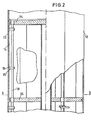
- the tail unit 2 arranged at the rear of the missile there is an essentially hollow-cylindrical part of the missile 10, which is delimited on the outside by a tubular casing 12.
- This envelope 12 encloses a payload space 4, in which payloads 11 are arranged separately, if necessary, by floors 24 extending transversely to the longitudinal axis of the missile 10.
- these payloads 11 In order to be able to cover the widest possible terrain strip along the trajectory of the missile with payloads 11 to be ejected, these payloads 11 must be ejected in the radial direction, that is, perpendicular to the direction of travel of the missile 10. For this purpose, it is necessary that at a predeterminable point in time, namely when the missile 10 has reached a specific point on its trajectory, the tubular envelope surrounding the payload space 4 is removed in order to enable the payloads to be ejected in the radial direction.
- the invention is particularly concerned with the configuration of the tubular shell 12 of the missile, which has to withstand considerable acceleration values both in the longitudinal axis direction of the missile 10 and in the circumferential direction when the missile 10 is launched and moved.
- the cover 12 must nevertheless be easily ejectable in order to enable the unimpeded ejection of the payloads 11.
- FIG. 2 shows a partial sectional illustration in the longitudinal axis direction of the missile 10 in the region of the payload space of the missile 10.
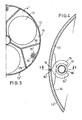
- FIG. 3 shows a view of a cross-sectional plane of the missile 10 as viewed from line 3 - 3 according to FIG. Fig. 2.
- FIG. 4 shows a detailed illustration from FIG. 3 on a substantially enlarged scale.
- the tubular casing 12 consists of a plurality of segments 13, 13 'which are detachably connected to one another and which abut one another with their side edges 16, 16' in such a way that they essentially form a cylinder jacket surface.
- the segments 13, 13 ' are expediently made of an elastic material, so that their bending on a cylindrical surface causes a resetting force.
- the segments 13, 13 ' can therefore only be forced into the cylinder shape using a prestress and can be braced in this position.
- FIG. 5 shows a partial sectional view in the longitudinal axis direction of the missile 10 in the region of such a rod 18.
- the rod 18 has eccentric and / or conical or stepped seats 19 in the region of the hook-shaped extensions 15, 15 ', to which the hook-shaped extensions 15, 15 'can create, whereby they can be clamped against each other when the rod 18 moves relative to the hook-shaped extensions 15, 15'.
- this bracing is achieved by moving the rod 18 during the assembly of the segments 13, 13 'in the longitudinal axis direction of the missile 10.
- the hook-shaped extensions 15, 15 ' can be braced by rotating the rod 18 about its longitudinal axis and / or simultaneous longitudinal movement of the rod 18 in the longitudinal axis direction of the missile 10.
- the locking of the segments 13, 13 'achieved with the aid of the rod 18 can be canceled in a simple manner after the predetermined ejection point of the payloads 11 has been reached by the rod 18 being moved and / or rotated in the opposite direction, as in the case of assembly.
- This longitudinal or rotational movement of the rod 18 naturally requires a certain force.
- This can be provided in a particularly simple and reliable manner by means of a pyrotechnic charge 20 provided with an optionally electrically activatable igniter 21.
- the rod 18 is expediently designed as a hollow cylinder which is closed on one side and rests with its open end piece 22 on the pyrotechnic charge 20.
- the gases generated when the pyrotechnic charge 20 is ignited can consequently penetrate through the open end piece 22 of the rod 18 into its interior and exert a force on its end face opposite the open end piece. Since the pyrotechnic charge 20 also acts on the circular surface of the rod 18 with which it rests on the pyrotechnic charge 20, a pressure-tensile force on the rod 18 results in a particularly advantageous manner, which moves it in the longitudinal axis direction of the missile and thereby unlocking the segments 13, 13 'leads.
- floors 24 are provided which extend transversely to the longitudinal axis of the missile 10, on the lateral surface 25 of which the segments 13, 13 'rest with their inner surface.
- grooves 26 are embedded in the lateral surfaces 25 of the bottoms, into which a collar 27 arranged on the segments 13, 13' engages.
- grooves 26 and collar 27 are preferably wedge-shaped in cross section (FIG. 6).
- the missile At launch, the missile is given a rotational movement about its longitudinal axis, which can also be maintained or reinforced during flight, if necessary, by additionally arranged engines.
- This rotational movement leads to force components directed transversely to the longitudinal axis, which act on the segments 12, 13 'forming the shell 12 with the aim of torsion.
- the segments 13, 13' and the bottoms 24 are either hooked in the area of their wedge-shaped connection (FIG. 7) or equipped with interlocking teeth 28 (FIG. 8).
- Fig. 8 shows a sectional view along the line 8 - gem.
- the segments 13, 13 ' are preferably produced from light metals commonly used in aircraft construction or also from plastic, in particular fiber-reinforced plastic.
- a support structure extending in the longitudinal axis direction of the missile is advantageously provided, which on the one hand divides the payload space 4 into individual compartments 4 'for receiving a payload 11 each and which on the other hand offers support points or support surfaces 29 to which the segments 13, 13 'can also support with their inner surface 14.
- the support structure expediently comprises partition walls 30 which are arranged parallel to the longitudinal axis of the missile and which enclose an angle between them and which partition off the rods 18, the hook-shaped extensions 15, 15 'and the joints between the segments 13, 13' in relation to the payloads 11 .
- the segments 13, 13 'simultaneously serve to hold additional or correction engines, which, for example during the flight phase of the missile 10, maintain or reinforce the swirl communicated to it during takeoff. These additional or correction engines are then separated from the missile together with the segments 13, 13 'when unlocked.
- the unlocking of the segments 13, 13 ' can be carried out simultaneously or with a time delay if necessary.
- the chronological order can be checked by activating the pyrotechnic charges 20.
- the ejection of the payloads 11 can either take place simultaneously with the separation of the segments 13, 13 'or take place with a time delay.
- the latter possibility allows the targeted ejection of a payload 11 in correlation to the rotational movement of the missile 10 with respect to its longitudinal axis. This proves to be particularly expedient in those cases in which a large radial throw range is aimed at when the payloads 11 are ejected.
Landscapes
- Engineering & Computer Science (AREA)
- Chemical & Material Sciences (AREA)
- Combustion & Propulsion (AREA)
- General Engineering & Computer Science (AREA)
- Aiming, Guidance, Guns With A Light Source, Armor, Camouflage, And Targets (AREA)
- Toys (AREA)
- Elimination Of Static Electricity (AREA)
Claims (10)
Applications Claiming Priority (2)
| Application Number | Priority Date | Filing Date | Title |
|---|---|---|---|
| DE3142313 | 1981-10-24 | ||
| DE19813142313 DE3142313A1 (de) | 1981-10-24 | 1981-10-24 | Flugkoerper |
Publications (3)
| Publication Number | Publication Date |
|---|---|
| EP0077954A2 EP0077954A2 (fr) | 1983-05-04 |
| EP0077954A3 EP0077954A3 (en) | 1983-11-16 |
| EP0077954B1 true EP0077954B1 (fr) | 1986-08-13 |
Family
ID=6144802
Family Applications (1)
| Application Number | Title | Priority Date | Filing Date |
|---|---|---|---|
| EP82109324A Expired EP0077954B1 (fr) | 1981-10-24 | 1982-10-08 | Missile |
Country Status (7)
| Country | Link |
|---|---|
| US (1) | US4524694A (fr) |
| EP (1) | EP0077954B1 (fr) |
| JP (1) | JPS5883199A (fr) |
| AU (1) | AU555916B2 (fr) |
| CA (1) | CA1186561A (fr) |
| DE (2) | DE3142313A1 (fr) |
| ES (1) | ES8309004A1 (fr) |
Families Citing this family (6)
| Publication number | Priority date | Publication date | Assignee | Title |
|---|---|---|---|---|
| ES2000853A6 (es) * | 1986-08-08 | 1988-03-16 | Esperanza & Cie Sa | Proyectil portador para mortero |
| FR2617464B1 (fr) * | 1987-07-03 | 1990-02-16 | Thomson Brandt Armements | Dispositif de fermeture ejectable, notamment pour roquettes a sous-munitions |
| FR2641858B1 (fr) * | 1989-01-17 | 1991-03-15 | Thomson Brandt Armements | Dispositif de deverrouillage pneumatique pour munitions largables a partir d'un vecteur |
| FR2656414B1 (fr) * | 1989-12-22 | 1993-01-22 | Thomson Brandt Armements | Systemes de retenue de sous-munitions embarquees dans un vecteur. |
| SE503719C2 (sv) * | 1992-06-30 | 1996-08-12 | Bofors Ab | Sätt och anordning för separation av substridsdelar |
| US6003809A (en) * | 1997-02-25 | 1999-12-21 | Honigsbaum; Richard F. | Process and apparatus for discouraging countermeasures against a weapon transport device |
Family Cites Families (17)
| Publication number | Priority date | Publication date | Assignee | Title |
|---|---|---|---|---|
| DE298070C (fr) * | ||||
| US2450910A (en) * | 1938-10-07 | 1948-10-12 | George M O'rear | Aerial bomb |
| GB589334A (en) * | 1943-05-31 | 1947-06-18 | Jack Imber | Improvements in or relating to aerial bombs, flares and the like which are dropped from aircraft |
| US2604043A (en) * | 1946-05-16 | 1952-07-22 | Foster Wheeler Corp | Bomb |
| US2809583A (en) * | 1952-12-04 | 1957-10-15 | Roman L Ortynsky | Cluster bomb |
| US3016011A (en) * | 1956-07-11 | 1962-01-09 | Brown Fred | Cluster opening method |
| US3088404A (en) * | 1956-11-15 | 1963-05-07 | Brown Fred | Interlocking screw threads |
| US3215082A (en) * | 1962-09-24 | 1965-11-02 | Aerojet General Co | Rapid release device for connecting rocket stages |
| US3253842A (en) * | 1963-12-10 | 1966-05-31 | Thiokol Chemical Corp | Shear key joint |
| US3461801A (en) * | 1968-01-25 | 1969-08-19 | Us Navy | Multi-canister ejecting device |
| DE1955777C3 (de) * | 1969-11-06 | 1979-11-22 | Messerschmitt-Boelkow-Blohm Gmbh, 8000 Muenchen | Gefechtskopf |
| US4178851A (en) * | 1972-03-08 | 1979-12-18 | The United States Of America As Represented By The Secretary Of The Army | Dual purpose munition |
| DE2558060C2 (de) * | 1975-12-22 | 1986-01-23 | Rheinmetall GmbH, 4000 Düsseldorf | Trägergeschoß für ausstoßbare Körper |
| DE2739299C2 (de) * | 1977-09-01 | 1984-01-19 | Messerschmitt-Bölkow-Blohm GmbH, 8000 München | Halterung für Streuwaffengroßbehälter |
| US4120519A (en) * | 1977-10-03 | 1978-10-17 | The Bendix Corporation | Collet type cylinder separation device |
| DE2903938A1 (de) * | 1979-02-02 | 1980-08-14 | Messerschmitt Boelkow Blohm | Streumunition |
| DE2920347C2 (de) * | 1979-05-19 | 1982-11-11 | Messerschmitt-Bölkow-Blohm GmbH, 8000 München | Gefechtskopf mit ausstoßbaren Wirkkörpern |
-
1981
- 1981-10-24 DE DE19813142313 patent/DE3142313A1/de not_active Withdrawn
-
1982
- 1982-09-22 AU AU88626/82A patent/AU555916B2/en not_active Ceased
- 1982-10-08 EP EP82109324A patent/EP0077954B1/fr not_active Expired
- 1982-10-08 DE DE8282109324T patent/DE3272598D1/de not_active Expired
- 1982-10-20 ES ES516686A patent/ES8309004A1/es not_active Expired
- 1982-10-22 CA CA000414049A patent/CA1186561A/fr not_active Expired
- 1982-10-22 US US06/436,076 patent/US4524694A/en not_active Expired - Fee Related
- 1982-10-22 JP JP57184806A patent/JPS5883199A/ja active Pending
Also Published As
| Publication number | Publication date |
|---|---|
| CA1186561A (fr) | 1985-05-07 |
| AU555916B2 (en) | 1986-10-16 |
| ES516686A0 (es) | 1983-10-16 |
| DE3272598D1 (en) | 1986-09-18 |
| US4524694A (en) | 1985-06-25 |
| EP0077954A2 (fr) | 1983-05-04 |
| ES8309004A1 (es) | 1983-10-16 |
| AU8862682A (en) | 1983-04-28 |
| EP0077954A3 (en) | 1983-11-16 |
| JPS5883199A (ja) | 1983-05-18 |
| DE3142313A1 (de) | 1983-05-05 |
Similar Documents
| Publication | Publication Date | Title |
|---|---|---|
| EP0114602B1 (fr) | Missile | |
| DE69500842T2 (de) | Abschlussvorrichtung und mit einer lenkvorrichtung versehene rakete | |
| DE2828251C1 (de) | Patronierte Munition mit Geschoss und verbrennbarer oder teilverbrennbarer Huelse | |
| DE69012300T2 (de) | Peripheriemantel für einen rohrabgeschossenen gelenkten Flugkörper. | |
| DE69004604T2 (de) | Leitwerkausspreizungssystem für ein Geschoss. | |
| DE69129815T2 (de) | Penetratormunition für Ziele mit hohem mechanischem Widerstand | |
| DE2907308C2 (de) | Geschoß mit mindestens einem ausstoßbaren Tochtergeschoß | |
| EP0077954B1 (fr) | Missile | |
| DE2227104A1 (de) | Geschoss oder rakete mit aufklappbarem leitwerk | |
| DE3781874T2 (de) | Bombe mit splitterhuelle. | |
| EP0551635A1 (fr) | Magasin pour munitions dans la tourrelle d'un véhice de combat | |
| DE2920347A1 (de) | Gefechtskopf mit ausstossbaren wirkkoerpern | |
| DE3506889A1 (de) | Flugkoerper | |
| DE2153994A1 (de) | Auswurfkopf, insbesondere fuer raketen | |
| DE69210070T2 (de) | Munitionsabschussvorrichtung | |
| DE2857576C1 (de) | Gefechtskopf | |
| DE3412701C2 (de) | Verbindungsvorrichtung | |
| CH692142A5 (de) | Nutzlastteil einer Rakete, mit einer Nutzlastverkleidung und einem Zentralteil. | |
| DE3428469C2 (fr) | ||
| DE2627505C3 (de) | Vorrichtung zur Lagerung, zum Transport und Abschuß von Flugkörpern | |
| DE2739299C2 (de) | Halterung für Streuwaffengroßbehälter | |
| DE3609865C1 (de) | Gefechtskopf mit einer Hohlladung | |
| DE2822355A1 (de) | Transport- und abschussbehaelter | |
| EP0265609A2 (fr) | Dispositif d'éjection des conteneurs, notamment de munition | |
| DE3903096C2 (fr) |
Legal Events
| Date | Code | Title | Description |
|---|---|---|---|
| PUAI | Public reference made under article 153(3) epc to a published international application that has entered the european phase |
Free format text: ORIGINAL CODE: 0009012 |
|
| AK | Designated contracting states |
Designated state(s): BE DE FR GB IT NL SE |
|
| PUAL | Search report despatched |
Free format text: ORIGINAL CODE: 0009013 |
|
| AK | Designated contracting states |
Designated state(s): BE DE FR GB IT NL SE |
|
| 17P | Request for examination filed |
Effective date: 19830922 |
|
| GRAA | (expected) grant |
Free format text: ORIGINAL CODE: 0009210 |
|
| ITF | It: translation for a ep patent filed | ||
| AK | Designated contracting states |
Kind code of ref document: B1 Designated state(s): BE DE FR GB IT NL SE |
|
| REF | Corresponds to: |
Ref document number: 3272598 Country of ref document: DE Date of ref document: 19860918 |
|
| ET | Fr: translation filed | ||
| PLBE | No opposition filed within time limit |
Free format text: ORIGINAL CODE: 0009261 |
|
| STAA | Information on the status of an ep patent application or granted ep patent |
Free format text: STATUS: NO OPPOSITION FILED WITHIN TIME LIMIT |
|
| 26N | No opposition filed | ||
| PGFP | Annual fee paid to national office [announced via postgrant information from national office to epo] |
Ref country code: NL Payment date: 19871031 Year of fee payment: 6 |
|
| PG25 | Lapsed in a contracting state [announced via postgrant information from national office to epo] |
Ref country code: NL Effective date: 19890501 |
|
| NLV4 | Nl: lapsed or anulled due to non-payment of the annual fee | ||
| PGFP | Annual fee paid to national office [announced via postgrant information from national office to epo] |
Ref country code: SE Payment date: 19890906 Year of fee payment: 8 |
|
| PGFP | Annual fee paid to national office [announced via postgrant information from national office to epo] |
Ref country code: DE Payment date: 19890914 Year of fee payment: 8 |
|
| ITTA | It: last paid annual fee | ||
| PG25 | Lapsed in a contracting state [announced via postgrant information from national office to epo] |
Ref country code: BE Effective date: 19891031 |
|
| PGFP | Annual fee paid to national office [announced via postgrant information from national office to epo] |
Ref country code: GB Payment date: 19891031 Year of fee payment: 8 |
|
| BERE | Be: lapsed |
Owner name: RHEINMETALL G.M.B.H. Effective date: 19891031 |
|
| PG25 | Lapsed in a contracting state [announced via postgrant information from national office to epo] |
Ref country code: FR Effective date: 19900629 |
|
| REG | Reference to a national code |
Ref country code: FR Ref legal event code: ST |
|
| PG25 | Lapsed in a contracting state [announced via postgrant information from national office to epo] |
Ref country code: GB Effective date: 19901008 |
|
| PG25 | Lapsed in a contracting state [announced via postgrant information from national office to epo] |
Ref country code: SE Effective date: 19901009 |
|
| GBPC | Gb: european patent ceased through non-payment of renewal fee | ||
| PG25 | Lapsed in a contracting state [announced via postgrant information from national office to epo] |
Ref country code: DE Effective date: 19910702 |
|
| EUG | Se: european patent has lapsed |
Ref document number: 82109324.2 Effective date: 19910603 |