EP0078049B1 - Dispositif de renforcement de la soudure en bout de deux fibres optiques - Google Patents
Dispositif de renforcement de la soudure en bout de deux fibres optiques Download PDFInfo
- Publication number
- EP0078049B1 EP0078049B1 EP82109871A EP82109871A EP0078049B1 EP 0078049 B1 EP0078049 B1 EP 0078049B1 EP 82109871 A EP82109871 A EP 82109871A EP 82109871 A EP82109871 A EP 82109871A EP 0078049 B1 EP0078049 B1 EP 0078049B1
- Authority
- EP
- European Patent Office
- Prior art keywords
- fibers
- capillary tube
- sheaths
- optical fibres
- reinforcing
- Prior art date
- Legal status (The legal status is an assumption and is not a legal conclusion. Google has not performed a legal analysis and makes no representation as to the accuracy of the status listed.)
- Expired
Links
- 230000003287 optical effect Effects 0.000 title claims description 11
- 230000003014 reinforcing effect Effects 0.000 title claims description 8
- 229910000679 solder Inorganic materials 0.000 title 1
- 239000000835 fiber Substances 0.000 claims description 23
- 239000000853 adhesive Substances 0.000 claims description 12
- 230000001070 adhesive effect Effects 0.000 claims description 12
- 239000002184 metal Substances 0.000 claims description 8
- 229910001220 stainless steel Inorganic materials 0.000 claims description 5
- 239000010935 stainless steel Substances 0.000 claims description 5
- 239000007788 liquid Substances 0.000 claims description 4
- -1 acrylic poly-diester Chemical class 0.000 claims description 3
- 239000013307 optical fiber Substances 0.000 description 13
- VYPSYNLAJGMNEJ-UHFFFAOYSA-N Silicium dioxide Chemical compound O=[Si]=O VYPSYNLAJGMNEJ-UHFFFAOYSA-N 0.000 description 6
- 239000010410 layer Substances 0.000 description 4
- 230000005540 biological transmission Effects 0.000 description 3
- 230000002787 reinforcement Effects 0.000 description 3
- 229920005989 resin Polymers 0.000 description 3
- 239000011347 resin Substances 0.000 description 3
- 239000000377 silicon dioxide Substances 0.000 description 3
- KRHYYFGTRYWZRS-UHFFFAOYSA-N Fluorane Chemical compound F KRHYYFGTRYWZRS-UHFFFAOYSA-N 0.000 description 2
- 230000005855 radiation Effects 0.000 description 2
- 238000003466 welding Methods 0.000 description 2
- 229920001651 Cyanoacrylate Polymers 0.000 description 1
- MWCLLHOVUTZFKS-UHFFFAOYSA-N Methyl cyanoacrylate Chemical compound COC(=O)C(=C)C#N MWCLLHOVUTZFKS-UHFFFAOYSA-N 0.000 description 1
- 150000005690 diesters Chemical class 0.000 description 1
- 239000011521 glass Substances 0.000 description 1
- 238000007654 immersion Methods 0.000 description 1
- 238000012986 modification Methods 0.000 description 1
- 230000004048 modification Effects 0.000 description 1
- 238000002360 preparation method Methods 0.000 description 1
- 229920002050 silicone resin Polymers 0.000 description 1
- 239000002356 single layer Substances 0.000 description 1
- 239000012815 thermoplastic material Substances 0.000 description 1
Images
Classifications
-
- G—PHYSICS
- G02—OPTICS
- G02B—OPTICAL ELEMENTS, SYSTEMS OR APPARATUS
- G02B6/00—Light guides; Structural details of arrangements comprising light guides and other optical elements, e.g. couplings
- G02B6/24—Coupling light guides
- G02B6/255—Splicing of light guides, e.g. by fusion or bonding
- G02B6/2558—Reinforcement of splice joint
Definitions
- the present invention relates to a device for reinforcing the weld at the end of two optical fibers whose ends have been stripped of their mechanical protection sheath, comprising a metal capillary tube for reinforcing said weld, surrounding the sheaths with little play optical fibers on either side of these ends over a certain length of these sheaths.
- the document FR-A 2380559 or US-A 4196965 has already proposed a device for reinforcing the weld at the end of two optical fibers, the optical sheath of which has an index less than that of the core of the fibers, was removed in the area on either side of the weld.
- your optical fibers are surrounded by a two-layer sleeve, an internal layer of fluorinated resin or silicone resin, with a refractive index lower than that of the core of the fibers, and an external layer of metal. Space included.
- the sleeve between the sleeve and the core of the fibers can be filled with a resin with a refractive index lower than that of the core of the fibers, the sleeve then being able to comprise only a single layer of metal.
- the optical sheaths of thermoplastic material easy to separate from the core of the fibers, coming from fibers of inferior quality from the point of view of light transmission, and those of silica or glass, giving good quality optical fibers, are difficult to separate from the core of the fibers.
- the replacement of the optical sheath by a sleeve, even with an internal resin layer with a refractive index lower than that of the fiber core risks creating a discontinuity in the transmission of light radiation at the limit between the optical sheath. and the sleeve.
- the object of the present invention is to provide a reinforcement device which provides the weld zone with mechanical properties, in particular a tensile strength and elongation, similar to those of the original optical fiber, so that this weld zone is not systematically the place of a possible rupture. It also aims to provide a reinforcement device whose preparation is easy and which does not create discontinuity in the transmission of light radiation.
- the reinforcement device according to the invention is characterized in that the entire space remaining between the capillary tube and, on the one hand the stripped ends of the fibers, on the other hand by the sheaths thereof, is filled with a liquid adhesive which hardens in the absence of air, the outlet of each end of the capillary tube being closed by a drop of an adhesive which sets substantially faster than said liquid adhesive.
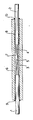
- Two sheathed optical fibers 1 and 2 were stripped by removing their mechanical protection sheath at their end zones 3 and 4, over a distance of about 20 mm, from on either side of their weld 5. This was treated by immersion in hydrofluoric acid at 48% by weight.
- the fibers, including their optical sheaths, are surrounded by a capillary tube 6 of stainless steel with high elasticity modulus, of the order of 15000, of length 100 mm, of external diameter 0.6 mm and of thickness 0 , 15 mm.
- the internal space 7 remaining between the stripped fibers and the capillary tube, and the space 8 comprised between the mechanical protection sheaths of the fibers and the capillary tube, are filled with a hardening adhesive (6 days for example), hardening in the absence of air, for example an acrylic poly-diester, which, due to its fluidity, penetrates by capillarity into the entire volume between the fibers and the internal surface of the capillary tube.
- a hardening adhesive (6 days for example), hardening in the absence of air, for example an acrylic poly-diester, which, due to its fluidity, penetrates by capillarity into the entire volume between the fibers and the internal surface of the capillary tube.
- the setting of this adhesive for several days the ends of the fibers at the outlet of the capillary are immobilized by two drops 9, 10 of a quick-setting adhesive, such as a poly-cyanoacrylate, which makes it possible to handle almost immediately the junction, without however subjecting it to tensile stresses.
- the slow setting adhesive wets silica and stainless steel very well and perfectly fills the volume remaining between the fibers and the internal surface of the capillary, over the entire length of the latter, the tensile forces applied to the fibers are fully transmitted to the capillary tube.
- the mechanical properties of the latter are such that, under a tensile stress corresponding to the breaking load of the Unwelded fiber, it does not extend by a value greater than that which the unreinforced welded optical fiber can accept. A tensile strength identical to that of the seamless sheathed optical fiber is thus obtained for the weld area, of the order of 4 to 6 daN for a silica fiber.
Landscapes
- Physics & Mathematics (AREA)
- Engineering & Computer Science (AREA)
- Plasma & Fusion (AREA)
- General Physics & Mathematics (AREA)
- Optics & Photonics (AREA)
- Mechanical Coupling Of Light Guides (AREA)
Description
- La présente invention concerne un dispositif de renforcement de la soudure en bout de deux fibres optiques dont les extrémités ont été dénudées de leur gaine de protection mécanique, comprenant un tube capillaire en métal pour le renforcement de ladite soudure, entourant avec un faible jeu les gaines des fibres optiques de part et d'autre de ces extrémités sur une certaine longueur de ces gaines.
- On sait que les caractéristiques mécaniques des fibres optiques de part et d'autre d'une soudure, notamment leur allongement à la rupture, sont environ 20 fois inférieures à celles de la fibre originale. De ce fait, lorsqu'une fibre d'une liaison optique est soumise à une contrainte de traction, les zones des soudures en constituent les éléments les plus faibles, et sa rupture, lorsqu'elle a lieu, se produit à leur niveau.
- On a déjà= proposé dans le document "A34-Mbit/s optical field trial system," E. Adler, H. Haupt, W. Zschunke, 4th European Conference on optical communication, Genova,, 12-1i5 Sept. 1978, de renforcer une zone de soudure d'une fibre optique à l'aide d'un tube en métal malléable de faible module d'élasticité, serti sur les gaines des fibres de part et d'autre des extrémités dénudées. On augmente dans une certaine mesure les propriétés mécaniques de la zone de soudure, mais celles-ci restent encore très inférieures à celles de la fibre originale.
- On a en outre déjà proposé dans le document FR-A 2380559 ou US-A 4196965, un dispositif de renforcement de la soudure en bout de deux fibres optiques dont la gaine optique, d'indice inférieure à celui du _ coeur des fibres, a été enlevée dans la zone de part et d'autre de la soudure. Dans cette zone, tes fibres optiques sont entourées par un manchon à deux couches, une couche interne en résine fluorée ou résine silicone, d'indice de réfraction inférieur à celui du coeur des fibres, et une couche externe en métal. L'espace compris. entre le manchon et le coeur des fibres peut être rempli d'une résine d'indice de réfraction inférieur à celui du coeur des fibres, le manchon pouvant alors ne comprendre qu'une seule couche en métal. Cependant, les gaines optiques en matière thermoplastique, facile à séparer du coeur des fibres, provenant des fibres de qualité inférieure du point de vue de la transmission de la lumière, et celles en silice ou en verre, donnant des fibres optiques de bonne qualité, sont difficiles à séparer du coeur des fibres. Par ailleurs, le remplacement de la gaine optique par un manchon, même à couche interne en résine d'indice de réfraction inférieur à celui de coeur des fibres, risque de créer une discontinuité dans la transmission de rayonnement lumineux à la limite entre la gaine optique et le manchon.
- La présente invention a pour but de procurer un dispositif de renforcement qui assure à la zone de la soudure des propriétés mécaniques, notamment une résistance et un allongement à la traction, voisines de celles de la fibre optique originale, de sorte que cette zone de soudure ne soit pas systématiquement le lieu d'une rupture éventuelle. Elle a encore pour but de procurer un dispositif de renforcement dont la préparation soit facile et qui ne crée par de discontinuité dans la transmission du rayonnement lumineux.
- Le dispositif de renforcement selon l'invention est caractérisé en ce que tout l'espace subsistant entre le tube capillaire et, d'une part les extrémités dénudées des fibres, d'autre par les gaines de celles-ci, est rempli d'un adhésif liquide qui durcit en l'absence d'air, la sortie de chaque extrémité du tube capillaire étant obturée par une goutte d'un adhésif à prise substantiellement plus rapide que ledit adhésif liquide.
- Il répond en outre de préférence à au moins l'une des caractéristiques suivantes:
- - L'adhesif à prise lente est un poly-diester acrylique.
- - Le métal du tube capillaire est une acier inoxydable.
- - L'épaisseur du tube est d'environ le quart de son diamètre extérieur.
- Il est décrit ci-après, à titre d'exemple et en référence à la figure du dessin annexé, un dispositif de renforcement de la soudure en bout de deux fibres optiques pour câble de télécommunications.
- Deux fibres optiques gainées 1 et 2, de diamètre un peu inférieur à 0,25 mm, ont été dénudées par enlèvement de leur gaine de protection mécanique à leurs zones d'extrémités 3 et 4, sur une distance d'environ 20 mm, de part et d'autre de leur soudure 5. Celle-ci a été traitée par immersion dans de J'acide fluorhydrique à 48% en poids. Les fibres, y compris leurs gaines optiques, sont entourées par un tube capillaire 6 en acier inoxydable à haut module d'élasticité, de l'ordre de 15000, de longueur 100 mm, de diamètre extérieur 0,6 mm et d'épaisseur 0,15 mm. L'espace interne 7 subsistant entre les fibres dénudées et le tube capillaire, et l'espace 8 compris entre les gaines de protection mécanique des fibres et le tube capillaire, sont remplis par un adhésif à prise lente (6 jours par exemple), durcissant en l'absence d'air, par exemple un poly-diester acryii- que, qui, du fait de sa fluidité, pénètre par capillarité dans tout le volume compris entre les fibres et la surface interne du tube capillaire. La prise de cet adhésif durant plusieurs jours, les extrémités des fibres à la sortie du capillaire sont immobilisées par deux gouttes 9, 10 d'un adhésif à prise rapide, tel qu'un poly-cyanoacrylate, ce qui permet de manipuler presque immédiatement la jonction, sans cependant la soumettre à des contraintes de traction.
- Du fait que l'adhésif à prise lente mouille très bien la silice et l'acier inoxydable et remplit parfaitement le volume subsistant entre les fibres et la surface interne du capillaire, sur toute la longueur de ce dernier, les efforts de traction appliqués aux fibres sont intégralement transmis au tube capillaire. Les propriétés mécanique de celui-ci sont telles que, sous une contrainte de traction correspondant à la charge de rupture de la fibre non soudée, il ne s'allonge pas d'une valeur supérieure à celle que la fibre optique soudée non renforcée peut accepter. On obtient ainsi pour la zone de la soudure une résistance à la traction identique à celle de la fibre optique gainée sans soudure, de l'ordre de 4 à 6 daN pour une fibre de silice.
- Bien que le dispositif de renforcement de la soudure en bout de deux fibres optiques qui vient d'être décrit en référence à la figure du dessin paraisse la forme de réalisation préférable de l'invention, on comprendra que diverses modifications peuvent lui être apportées sans sortir du cadre de J'invention. En particulier, on peut substituer à l'acier inoxydable un autre métal de résistance mécanique comparable, et utiliser un tube de plus faible diamètre.
Claims (4)
Applications Claiming Priority (2)
| Application Number | Priority Date | Filing Date | Title |
|---|---|---|---|
| FR8120212A FR2515364B1 (fr) | 1981-10-28 | 1981-10-28 | Dispositif de renforcement de la soudure en bout de deux fibres optiques |
| FR8120212 | 1981-10-28 |
Publications (3)
| Publication Number | Publication Date |
|---|---|
| EP0078049A2 EP0078049A2 (fr) | 1983-05-04 |
| EP0078049A3 EP0078049A3 (en) | 1984-03-28 |
| EP0078049B1 true EP0078049B1 (fr) | 1987-01-28 |
Family
ID=9263474
Family Applications (1)
| Application Number | Title | Priority Date | Filing Date |
|---|---|---|---|
| EP82109871A Expired EP0078049B1 (fr) | 1981-10-28 | 1982-10-26 | Dispositif de renforcement de la soudure en bout de deux fibres optiques |
Country Status (6)
| Country | Link |
|---|---|
| US (1) | US4537468A (fr) |
| EP (1) | EP0078049B1 (fr) |
| JP (1) | JPS5882215A (fr) |
| CA (1) | CA1218886A (fr) |
| DE (1) | DE3275323D1 (fr) |
| FR (1) | FR2515364B1 (fr) |
Families Citing this family (49)
| Publication number | Priority date | Publication date | Assignee | Title |
|---|---|---|---|---|
| GB8310131D0 (en) * | 1983-04-14 | 1983-05-18 | British Telecomm | Sealing assembly |
| US4585304A (en) * | 1983-09-06 | 1986-04-29 | Virginia | Technique for repairing and joining small diameter optical fiber cables |
| US4733933A (en) * | 1984-01-20 | 1988-03-29 | Hughes Aircraft Company | Fiber optic structure and method of making |
| WO1985003360A2 (fr) * | 1984-01-20 | 1985-08-01 | Hughes Aircraft Company | Structure de fibres optiques et procede de fabrication |
| JPS60185908A (ja) * | 1984-03-05 | 1985-09-21 | Takashi Mori | 光導体の連結構造 |
| US4756595A (en) * | 1986-04-21 | 1988-07-12 | Honeywell Inc. | Optical fiber connector for high pressure environments |
| US4763970A (en) * | 1987-08-07 | 1988-08-16 | Corning Glass Works | Non-pistoning capillary splice |
| US4807959A (en) * | 1987-08-07 | 1989-02-28 | Corning Glass Works | Method of splicing fibers |
| CA1321089C (fr) * | 1988-05-06 | 1993-08-10 | Adc Telecommunications, Inc. | Commutateur optique |
| US4888076A (en) * | 1988-07-05 | 1989-12-19 | Lockheed Corporation | Method of coupling optical fibers enbedded in a molded article to the exterior thereof |
| DE4030291C2 (de) * | 1989-09-25 | 2002-10-31 | Hitachi Cable | Verfahren zum Verbinden optischer Fasern, welche von Metallröhren umschlossen sind |
| US5157751A (en) * | 1992-01-14 | 1992-10-20 | Litton Systems, Inc. | Fiber optic splice protector and method for making same |
| JP3136741B2 (ja) * | 1992-02-07 | 2001-02-19 | 住友電気工業株式会社 | 光ファイバ補強方法 |
| CA2116934C (fr) * | 1994-03-03 | 2000-08-01 | Murray R. Harman | Methode de mise en contact de fibres optiques |
| USRE40150E1 (en) | 1994-04-25 | 2008-03-11 | Matsushita Electric Industrial Co., Ltd. | Fiber optic module |
| US5717813A (en) * | 1994-06-27 | 1998-02-10 | Fiberlign A Division Of Preformed Line Products (Canada) Ltd. | Fusion splice element for use in splicing optical fibers |
| US5740301A (en) * | 1994-06-27 | 1998-04-14 | Fiberlign Division Of Preformed Line Products Ltd. | Fusion splicing block with electrodes disposed on planar surface |
| US5481640A (en) * | 1994-06-27 | 1996-01-02 | Fiberlign Division Of Preformed Line Products (Canada) Ltd. | Tool for fusing optical fibers |
| US5568582A (en) * | 1994-10-13 | 1996-10-22 | Martin Marietta Energy Systems, Inc. | Fiber optic connector |
| US5717533A (en) | 1995-01-13 | 1998-02-10 | Methode Electronics Inc. | Removable optoelectronic module |
| US5546281A (en) * | 1995-01-13 | 1996-08-13 | Methode Electronics, Inc. | Removable optoelectronic transceiver module with potting box |
| US6220878B1 (en) | 1995-10-04 | 2001-04-24 | Methode Electronics, Inc. | Optoelectronic module with grounding means |
| US5642451A (en) * | 1995-12-28 | 1997-06-24 | The United States Of America As Represented By The Secretary Of The Navy | Fiberoptic cable junction |
| KR100219710B1 (ko) * | 1996-07-30 | 1999-09-01 | 윤종용 | 금속코팅 광섬유 접속 방법 |
| DE19649045A1 (de) * | 1996-11-27 | 1998-05-28 | Steinbeis Tz Kommunikationstec | Schutzvorrichtung |
| KR19980078178A (ko) * | 1997-04-25 | 1998-11-16 | 윤종용 | 광섬유의 융착접속부 보호 방법 및 장치 |
| US6203333B1 (en) | 1998-04-22 | 2001-03-20 | Stratos Lightwave, Inc. | High speed interface converter module |
| US6179627B1 (en) | 1998-04-22 | 2001-01-30 | Stratos Lightwave, Inc. | High speed interface converter module |
| US7090509B1 (en) | 1999-06-11 | 2006-08-15 | Stratos International, Inc. | Multi-port pluggable transceiver (MPPT) with multiple LC duplex optical receptacles |
| US6220873B1 (en) * | 1999-08-10 | 2001-04-24 | Stratos Lightwave, Inc. | Modified contact traces for interface converter |
| US6338579B1 (en) * | 2000-02-03 | 2002-01-15 | Robert F. Winiarski | Fiber optic sleeve assembly for use at a splice junction of a fiber optic cable |
| US6485199B1 (en) | 2000-04-13 | 2002-11-26 | Amherst Holding Co. | Disposable optical fiber splice sleeve and method for applying same |
| JP2007322749A (ja) * | 2006-06-01 | 2007-12-13 | Central Glass Co Ltd | 異種ファイバ融着接続部の補強構造 |
| USD607749S1 (en) | 2007-03-27 | 2010-01-12 | The Procter & Gamble Company | Dispensing package |
| JP5124225B2 (ja) * | 2007-05-15 | 2013-01-23 | 株式会社フジクラ | 光ファイバ融着接続構造 |
| JP2011525706A (ja) * | 2008-06-25 | 2011-09-22 | コラクティヴ ハイ−テック インコーポレイティド | 高出力光ファイバ部材用エネルギ放散パッケージ |
| DE102008062848A1 (de) * | 2008-12-23 | 2010-06-24 | Jt Optical Engine Gmbh + Co. Kg | Spleißverbindung zwischen zwei optischen Fasern sowie Verfahren zum Herstellen einer solchen Spleißverbindung |
| FR2997239B1 (fr) * | 2012-10-22 | 2016-01-01 | Commissariat Energie Atomique | Procede de fabrication d'un laser a fibre optique, et laser a fibre optique |
| GB2547211B (en) * | 2016-02-10 | 2022-03-16 | Bae Systems Plc | Waveguides |
| WO2017137737A1 (fr) | 2016-02-10 | 2017-08-17 | Bae Systems Plc | Guides d'ondes |
| US10422969B2 (en) | 2016-03-17 | 2019-09-24 | Ormond Energy Innovations Inc. | Protective fiber optic termination, system, and method of using same |
| EP3602155A1 (fr) | 2017-03-21 | 2020-02-05 | Corning Research & Development Corporation | Ensemble câble à fibres optiques avec épissure par fusion à sur-revêtement thermoplastique, et procédé et appareil associés |
| US11404815B2 (en) | 2017-10-30 | 2022-08-02 | Ormond Energy Innovations Inc. | Sealed connector with triggered mating and method of using same |
| US10976492B2 (en) | 2018-09-07 | 2021-04-13 | Corning Incorporated | Cable with overcoated non-coplanar groups of fusion spliced optical fibers, and fabrication method |
| PL3847491T3 (pl) | 2018-09-07 | 2026-03-30 | Corning Incorporated | Zespół rozprowadzający włókna optyczne z interfejsem wstęgowanym do jednoczesnego zgrzewania sposobem fuzji oraz sposób wytwarzania |
| US11360265B2 (en) | 2019-07-31 | 2022-06-14 | Corning Research & Development Corporation | Fiber optic cable assembly with overlapping bundled strength members, and fabrication method and apparatus |
| US11886009B2 (en) | 2020-10-01 | 2024-01-30 | Corning Research & Development Corporation | Coating fusion spliced optical fibers and subsequent processing methods thereof |
| US11808983B2 (en) | 2020-11-24 | 2023-11-07 | Corning Research & Development Corporation | Multi-fiber splice protector with compact splice-on furcation housing |
| US11867947B2 (en) | 2021-04-30 | 2024-01-09 | Corning Research & Development Corporation | Cable assembly having routable splice protectors |
Family Cites Families (12)
| Publication number | Priority date | Publication date | Assignee | Title |
|---|---|---|---|---|
| DE1109891B (de) * | 1955-08-25 | 1961-06-29 | American Sealants Company | Unter Luftausschluss polymerisierende fluessige Gemische |
| US3041322A (en) * | 1959-07-20 | 1962-06-26 | Vernon K Krieble | Anaerobic curing compositions containing acrylic acid diesters |
| US3046262A (en) * | 1960-08-19 | 1962-07-24 | Vernon K Krieble | Accelerated anaerobic curing compositions |
| US3043820A (en) * | 1960-10-14 | 1962-07-10 | Robert H Krieble | Anaerobic curing sealant composition having extended shelf stability |
| US3218305A (en) * | 1963-12-26 | 1965-11-16 | Loctite Corp | Accelerated anaerobic compositions and method of using same |
| AT325326B (de) * | 1972-07-10 | 1975-10-10 | Siemens Ag | Verbindungsstecker für optische glasfasern und verfahren zur herstellung fester verbindungen unter verwendung eines verbindungssteckers |
| GB1433755A (en) * | 1973-09-01 | 1976-04-28 | Plessey Co Ltd | In-line coupling of two lengths of linear optical waveguide elements |
| AU489529B1 (en) * | 1973-11-09 | 1976-05-13 | Commonwealth Scientific And Industrial Research Organization | Joining and termination of light fibres |
| DE2363987A1 (de) * | 1973-12-21 | 1975-07-10 | Siemens Ag | Verfahren zur verbindung von lichtwellenleitern |
| US3904269A (en) * | 1974-01-28 | 1975-09-09 | Us Navy | Fiber optic cable connector |
| JPS50118733A (fr) * | 1974-02-28 | 1975-09-17 | ||
| JPS5921530B2 (ja) * | 1977-02-11 | 1984-05-21 | 住友電気工業株式会社 | プラスチッククラッド形、光ファイバ−の接続方法 |
-
1981
- 1981-10-28 FR FR8120212A patent/FR2515364B1/fr not_active Expired
-
1982
- 1982-10-20 US US06/435,592 patent/US4537468A/en not_active Expired - Fee Related
- 1982-10-26 JP JP57188108A patent/JPS5882215A/ja active Pending
- 1982-10-26 DE DE8282109871T patent/DE3275323D1/de not_active Expired
- 1982-10-26 EP EP82109871A patent/EP0078049B1/fr not_active Expired
- 1982-10-27 CA CA000414262A patent/CA1218886A/fr not_active Expired
Also Published As
| Publication number | Publication date |
|---|---|
| US4537468A (en) | 1985-08-27 |
| EP0078049A2 (fr) | 1983-05-04 |
| JPS5882215A (ja) | 1983-05-17 |
| EP0078049A3 (en) | 1984-03-28 |
| DE3275323D1 (en) | 1987-03-05 |
| FR2515364B1 (fr) | 1985-07-05 |
| CA1218886A (fr) | 1987-03-10 |
| FR2515364A1 (fr) | 1983-04-29 |
Similar Documents
| Publication | Publication Date | Title |
|---|---|---|
| EP0078049B1 (fr) | Dispositif de renforcement de la soudure en bout de deux fibres optiques | |
| CA1224653A (fr) | Technique de reparation et d'epissure de cables a fibres optiques | |
| JP2709388B2 (ja) | 光ファイバ接続方法および接続構造ならびに光ファイバ接続構造の加工方法 | |
| EP0534819B1 (fr) | Procédé pour limiter les pertes par couplage entre une fibre optique monomode et un système optique de diamétre de mode inférieur ou entre deux fibres optiques monomodes de même diamétre de mode | |
| CA1085204A (fr) | Cable a fibres optiques et procede de realisation | |
| EP0849617A1 (fr) | Câble à fibres optiques à structure dissymétrique | |
| EP0019494A1 (fr) | Bielle de commande ou de transmission d'efforts | |
| FR2600425A1 (fr) | Conducteur de lumiere a fibres optiques resistant aux temperatures elevees dans sa zone de surface frontale et procede pour sa fabrication | |
| EP0902310B1 (fr) | Structures de câbles à fibres optiques autorésistantes à la compression | |
| EP0720034A1 (fr) | Câble à fibres optiques et procédé de fabrication d'un tel câble | |
| EP0674197B1 (fr) | Procédé de réalisation d'un élément de raccordement à une fibre multicoeurs | |
| FR2531158A1 (fr) | Arbre soumis a la torsion, notamment arbre de transmission | |
| FR2568737A1 (fr) | Ligne sous-marine pour telecommunications a fibres optiques | |
| EP0703479A1 (fr) | Câble à fibres optiques | |
| FR2659750A1 (fr) | Cable a fibre optique. | |
| FR2497964A1 (fr) | Cable a fibres optiques, pourvu d'elements de renforcement mecanique | |
| JP2003167145A (ja) | 光ファイバとその接続構造及び接続方法 | |
| JP3450104B2 (ja) | 光カプラ | |
| EP0654617B1 (fr) | Articulation élastique à rigidité axiale contrÔlée | |
| EP0184050B1 (fr) | Dipositif de raccordement d'un câble à fibres optiques à un boîtier de jonction, et procédé de fabrication de ce dispositif | |
| CA1134469A (fr) | Liaison entre ame en fibres agglomerees et armature d'ancrage d'un isolateur electrique | |
| EP0456026A1 (fr) | Dispositif optique à composant d'optique intégrée et procédé de fabrication | |
| FR2548391A1 (fr) | Procede de formation d'une lentille de couplage a l'extremite d'une fibre optique sur le coeur de celle-ci | |
| US7083334B2 (en) | Hermetically sealed optical fiber ferrule assembly supporting multiple optical fibers | |
| EP0628842B1 (fr) | Dispositif pour connecter une fibre optique monomode en verre fluoré à une fibre optique monomode en silice |
Legal Events
| Date | Code | Title | Description |
|---|---|---|---|
| PUAI | Public reference made under article 153(3) epc to a published international application that has entered the european phase |
Free format text: ORIGINAL CODE: 0009012 |
|
| AK | Designated contracting states |
Designated state(s): CH DE FR GB IT LI NL SE |
|
| PUAL | Search report despatched |
Free format text: ORIGINAL CODE: 0009013 |
|
| AK | Designated contracting states |
Designated state(s): CH DE FR GB IT LI NL SE |
|
| 17P | Request for examination filed |
Effective date: 19840925 |
|
| GRAA | (expected) grant |
Free format text: ORIGINAL CODE: 0009210 |
|
| AK | Designated contracting states |
Kind code of ref document: B1 Designated state(s): CH DE FR GB IT LI NL SE |
|
| REF | Corresponds to: |
Ref document number: 3275323 Country of ref document: DE Date of ref document: 19870305 |
|
| ITF | It: translation for a ep patent filed | ||
| PLBE | No opposition filed within time limit |
Free format text: ORIGINAL CODE: 0009261 |
|
| STAA | Information on the status of an ep patent application or granted ep patent |
Free format text: STATUS: NO OPPOSITION FILED WITHIN TIME LIMIT |
|
| 26N | No opposition filed | ||
| ITTA | It: last paid annual fee | ||
| EAL | Se: european patent in force in sweden |
Ref document number: 82109871.2 |
|
| PGFP | Annual fee paid to national office [announced via postgrant information from national office to epo] |
Ref country code: GB Payment date: 19950814 Year of fee payment: 14 Ref country code: CH Payment date: 19950814 Year of fee payment: 14 |
|
| PGFP | Annual fee paid to national office [announced via postgrant information from national office to epo] |
Ref country code: SE Payment date: 19950918 Year of fee payment: 14 Ref country code: DE Payment date: 19950918 Year of fee payment: 14 |
|
| PGFP | Annual fee paid to national office [announced via postgrant information from national office to epo] |
Ref country code: FR Payment date: 19950927 Year of fee payment: 14 |
|
| PGFP | Annual fee paid to national office [announced via postgrant information from national office to epo] |
Ref country code: NL Payment date: 19951031 Year of fee payment: 14 |
|
| PG25 | Lapsed in a contracting state [announced via postgrant information from national office to epo] |
Ref country code: GB Effective date: 19961026 |
|
| PG25 | Lapsed in a contracting state [announced via postgrant information from national office to epo] |
Ref country code: SE Effective date: 19961027 |
|
| PG25 | Lapsed in a contracting state [announced via postgrant information from national office to epo] |
Ref country code: LI Effective date: 19961031 Ref country code: CH Effective date: 19961031 |
|
| PG25 | Lapsed in a contracting state [announced via postgrant information from national office to epo] |
Ref country code: NL Effective date: 19970501 |
|
| REG | Reference to a national code |
Ref country code: CH Ref legal event code: PL |
|
| GBPC | Gb: european patent ceased through non-payment of renewal fee |
Effective date: 19961026 |
|
| PG25 | Lapsed in a contracting state [announced via postgrant information from national office to epo] |
Ref country code: FR Effective date: 19970630 |
|
| NLV4 | Nl: lapsed or anulled due to non-payment of the annual fee |
Effective date: 19970501 |
|
| PG25 | Lapsed in a contracting state [announced via postgrant information from national office to epo] |
Ref country code: DE Effective date: 19970701 |
|
| EUG | Se: european patent has lapsed |
Ref document number: 82109871.2 |
|
| REG | Reference to a national code |
Ref country code: FR Ref legal event code: ST |